Midea D30-15FA2 / D50-15FA2 / D80-15FA2 / D100-15FA2 Manuale del proprietario
- Tipo
- Manuale del proprietario

Storage Electric Water Heater
The diagram above is just for reference. Please take the
appearance of the actual product as the standard.
Instruction Manual
Model: D30-15FA2
D50-15FA2
D80-15FA2
D100-15FA2
Thank you very much for purchasing our water heater.
Before installing and operating your water heater, please
read this manual carefully and keep it for future reference.

1
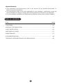
The installation and maintenance has to be carried out by qualified professials or
Midea authorized technicians.
The manufacturer shall not be held responsible for any damage or malfunction caused by
wrong installation or failing to comply with following instructions included in this pamphlet.
For more detailed installation and maintenance guidelines, please refer to below chapters.
TABLE OF CONTENTS
TITLE PAGE
1.CAUTIONS.......................................................................................................................(2)
2.PRODUCT INTRODUCTION ...........................................................................................(3)
3.UNIT INSTALLATION .......................................................................................................(5)
4.METHODS OF USING .....................................................................................................(7)
5.MAINTENANCE ...............................................................................................................(7)
6.TROUBLESHOOTING .....................................................................................................(8)
7.PRODUCE INFORMATION WITH EU REGULATION .....................................................(9)
●
●
●
General Remark

2
The supply socket must be earthed reliably. The rated current of the socket shall not be lower
than 10A. The socket and plug shall be kept dry to prevent electrical leakage. Inspect
frequently whether the plugs contact well with the socket. Inspect method is as follows: insert
the power supply plug into socket, after using for half an hour, shut down the unit and pull the
plug out, and inspect the plug whether it scalds hand. If it scalds (over 50), please change
another well-contacted socket to avoid the plug being damaged, fire or other personnel
accidents result from bad-contacting.
The installation height of the supply socket shall not be lower than 1.8m.
The wall in which the electrical water heater is installed shall be able to bear the load more than
two times of the heater filled fully with water without distortion and cracks. Otherwise, other
strengthening measures shall be adopted.
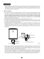
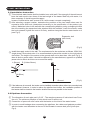
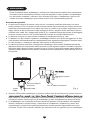
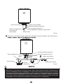
The pressure relief valve attached with the heater must be installed at the cold water inlet of
this heater(see Fig.1), and make sure it is not exposed in the foggy. The water may be
outflowed from pressure relief valve, so the outflow pipe must open wide in the air; The
pressure relief valve need to be checked and cleaned regularly, so as to make sure it will not
be blocked.
Before installing this water heater,check and confirm that the earthing on the supply socket is
reliably grounded. Otherwise, the electrical water heater can not be installed and used. Do not
use extension boards. Incorrect installation and use of this electrical water heater may result in
serious injuries and loss of property.
Special Cautions
1. CAUTIONS
●
●
●
●
(Fig.1)
●
●
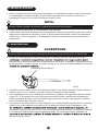
When using the heater for the first time(or the first use after maintenance), the heater can not
be switched on until it has been filled fully with water. When filling the water, at least one of the
outlet valves at the outlet of the heater must be opened to exhaust the air. This valve can be
closed after the heater has been filled fully with water.
The water heater is not intended for use by persons(including children) with reduced physical,
sensory or mental capabilities, or lack of experience and knowledge, unless they have been
given supervision or instructions concerning use of the appliance by a person responsible for
their safety. Children should be supervised to ensure that they do not play with the heater.
Hot water Cold water
Pressure
relief valve
Thread screw
Drain handle
Pressure release hole

3
2. PRODUCT INTRODUCTION
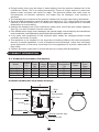
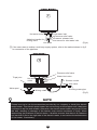
2.2 Brief introduction of product structure
●
●
●
●
●
●
●
●
During heating, there may be drops of water dripping from the pressure release hole of the
multifunction valves. This is a normal phenomenon. If there is a large amount of water leak,
please contact customer care center for repair. This pressure release hole shall, under no
circumstances, be blocked; otherwise, the heater may be damaged, even resulting in
accidents.
The drainage pipe connected to the pressure release hole must be kept sloping downwards.
Since the water temperature inside the heater can reach up to 75°C, the hot water must not be
exposed to human bodies when it is initially used. Adjust the water temperature to a suitable
temperature to avoid scalding.
Unscrew the thread screw on the multifunction safety valve, and lift the drain handle upwards.
(See Fig.1) to drain the water from the inner tank.
If the flexible power supply cord is damaged, the special supply cord provided by the manufacturer
must be selected, and replaced by the professional maintenance personnel.
If any parts and components of this electrical water heater are damaged please contact
customer care center for repair.
This appliance is not intended for use by persons (including children) with reduced physical,
sensory or mental capabilities, or lack of experience and knowledge, unless they have been
given supervision or instruction concerning use of the appliance by a person responsible for
their safety.
Children should be supervised to ensure that they do not play with the appliance.
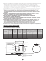
Model
Rated
Voltage
(ACV)
IPX4750.8220-2401500
28
D30-15FA2
Rated
Power
(W)
Volume
(L)
Rated
Pressure
(MPa)
Max Of Water
Temperature
(°C)
Protection
Class
Water
Proof
Class
2.1 Technical Performance Parameters
I
IPX4750.8220-240150047
D50-15FA2
I
IPX4750.8220-240150074
D80-15FA2
I
IPX4750.8220-240150093
D100-15FA2
I
C
B
A
Anode
Thermometer
Shell
Power cord
Cold water inlet
Hot water outlet
Heating indicator light
Heating element
Thermal insulation
Inner tank
D

4
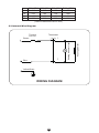
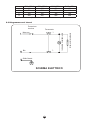
2.3 Internal Wire Diagram
WIRING DIAGRAM
(Note:All dimensions are in mm)
D50-15FA2
385
705
100
200
D80-15FA2
450
758
100
200
D100-15FA2
450
908
100
200
A
B
C
D
D30-15FA2
340
570
100
200
Heating Element
Heating Indicator Light
Thermal
Cut Out
Thermostat
Brown
Blue
Yellow/Green

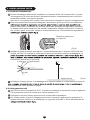
3.2 Pipelines Connection
3.1 Installation Instruction
①
②
3. UNIT INSTALLATION
5
This electrical water heater shall be installed on a solid wall. If the strength of the wall cannot
bear the load equal to two times of the total weight of the heater filled fully with water, it is
then necessary to install a special support.
Incase of hollow bricks wall, ensure to fill it with cement concrete completely.
After selecting a proper location, determine the positions of the two install holes used for
expansion bolts with hook (determined according to the specification of the product you
select). Make two holes in the wall with the corresponding depth by using a chopping bit with
the size matching the expansion bolts attached with the machine, insert the screws, make
the hook upwards, tighten the nuts to fix firmly, and then hang the electric water heater on it
(see Fig.2).
④
If the bathroom is too small, the heater can be installed at another place without sun-scorched and
rain-drenched. However, in order to reduce the pipeline heat losses, the installation position of
the heater shall be closed to the location shall be as near as possible to the heater.
(Fig.2)
Expansion bolt
(with hook)
①
②
③
The dimension of each pipe part is G1/2” ; The massive pressure of inlet should use Pa as
the unit; The minimum pressure of inlet should use Pa as the unit.
Connection of pressure relief valve with the heater on the inlet of the water heater.
In order to avoid leakage when connecting the pipelines, the rubber seal gaskets provided
with the heater must be added at the end of the threads to ensure leak proof joints (see
Fig.4).
(Fig.3)
N (Blue)
Ground
≥1.8m
L (Brown) E (Yellow/Green)
③
Install the supply socket in the wall. The requirements for the socket are as follows: 250V/10A,
single phase, three electrodes. It is recommended to placed the socket on the right above
the heater. The height of the socket to the ground shall not be less than 1.8m (see Fig.3). If
there is fault on power cable, it should be replaced by the manufacturers, agencies or qualified
person who is able to do this so as to ensure the safety.

NOTE
Please be sure to use the accessories provided by our company to install this electric
water heater. This electric water heater can not be hung on the support until it has been
confirmed to be firm and reliable. Otherwise, the electric water heater may drop off from
the wall, resulting in damage of the heater, even serious accidents of injury. When
determining the locations of the bolt holes, it shall be ensured that there is a clearance
not less than 0.2m on the right side of the electric heater, to convenient the maintenance
of the heater, if necessary.
If the users want to realize a multi-way supply system, refer to the method shown in fig.5
for connection of the pipelines.
④
6
(Fig.5)
Water inlet valve
Water inlet valve
Running water pipe
Mixing valve
Water pool
Triple joint
Shower nozzle
Hot water
outlet
Cold
water
inlet
Pressure relief valve
(Fig.4)
Hot water outlet Cold water inlet
Pressure relief valve
Pressure release hole
Joint screw for cold water inlet
Adjusting handle for
mixing valve
Hot water

Check the power plug and outlet as often as possible. Secure electrical contact and also proper
grounding must be provided. The plug and outlet must not heat excessively.
If the heater is not used for a long time, especially in regions with low air temperature(below
0°C), it is nessary to drain water from the heater to prevent damage of the water heater, due to
water freezing in the internal tank.(Refer Cautions in this manual for the method to drain away
the water from the inner container).
To ensure long reliable water heater operation, it is recommended to regularly clean the
internal tank and remove deposits on the electric heating element of the water heater, as well
as check condition (fully decomposed or not) of the magnesium anode and, if necessary,
replace it with a new one in case of full decomposition.Tank cleaning frequency depends on
hardness of water located in this territory. Cleaning must be performed by special maintenance
services. You can ask the seller for address of the nearest service center.
●
●
●
5. MAINTENANCE
WARNING
Do cut off power supply before maintenance, to avoid danger like electric shock.
!
7
4. METHODS OF USING
NOTE
During normal operation, the inlet valve shall be always kept open.
First, open any one of the outlet valves at the outlet of the water heater, then, open the inlet
valve. The water heater gets filled with water. When water flows out of the outlet pipe it implies
that the heater has been filled fully with water, and the outlet valve can be closed.
Insert the supply plug into the supply socket, the two indicator lights will light up this time.
The thermostat will automatically control the temperature. When the water temperature inside
the heater has reached the set temperature, it will switch off automatically, when the water
temperature falls below the set point the heater will be turned on automatically to restore the
heating.
●
●
●
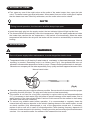
(Fig.6)
●
●
●
●
5. MAINTENANCE
WARNING
Do cut off power supply before maintenance, to avoid danger like electric shock.
!
Temperature limiter cut off electricty if water heater is overheated or thermostat damages. Manual
resetting is needed. Ressetting knob is as follows (see Fig.6). Non-professionals are not
allowed to disassemble temperature limiter to reset . Please contact prefessionals to maintain.
Otherwise our company will not take responsiblity if any quality accident happens because of this.
(Fig.6)
Manual reset button

6. TROUBLESHOOTING
8
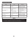
NOTE
Parts illustrated in this use and care manual are indicative only, parts provided with the
product may differ with illustrations.This product is intended for household use only.
Specifications are subject to change without notice.
Failures Reasons Treatment
The heating indicator
light is off.
Failures of the temperature
controller.
Contact with the professional
personnel for repair.
No water coming out
of the hot water outlet.
The water temperature
is too high.
Water leak.
1. The running water supply
is cut off.
2. The hydraulic pressure is
too low.
3. The inlet valve of running
water is not open.
1. Wait for restoration of
running water supply.
2. Use the heater again when
the hydraulic pressure is
increased.
3. Open the inlet valve of
running water.
Failures of the temperature
control system.
Seal problem of the joint
of each pipe.
Contact with the professional
personnel for repair.
Seal up the joints.

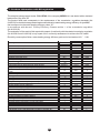
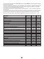
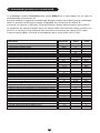
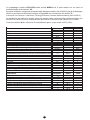
7. Produce information with EU regulation
The electrical storage water heater D30-15FA2 of the company MIDEA Ltd. was tested with a declared
load profile of the size “S”
The product fulfills and corresponds to the requirements of the commission regulation standards (No
814/2013) for electrical storage water heater and achieved a water heating energy efficiency of ηwh=32%
that correspond to the water heating efficiency class “C”
In accordance with Annex Enercy Efficiency Classes article 1 of the commission regulation
(No 812/2013)
The evaluation of the result of this report with respect of conformity with the related commission regulation
(No 812/2013 and 814/2019) is only a part of the conformity assessment to achieve the ErP-Label.
Electricity consumption Qelec, water heating energy efficiency ηwh and mixed water at 40V 40
65.7
60.3
10.7
60.3
24.1
40
0.23
0
0
2.5
-0.396
2.1
2.528
0.831
3.498
65.7
69.9
29.0
29.0
2.788
31.9
578
C
Description tinUeulaVretemaraP
k-Value k
Smart control compliance smart
Smart control factor SCF
Conversion coefficient CC
Ambient correction term Qcor kWh
Referenct energy QrefkWh
Useful energy content QH2O kWh
Correction ratio of reference and useful energy Qref/QH2O kWh
Daily electricity consumption (measured) Qtest_elec kWh
Water temperature at the beginning of the 24h measurement
cycle T3 ℃
Water temperature at the end of the 24h measurement cycle T5 ℃
Storage volume Mact kg
Storage volume Cact L
Daily electricity consumption (corrected) Qelec kWh
Water heating energy efficiency ηwh
Annual Electricity Consumption AEC kWh
Water heating energy efficiency class
Description Parameter Value Unit
Water temperature without tapping Tset ℃
Average water temperature of outlet warm water θ'p℃
Average water temperature of inlet cold water θc℃
Normalised value of the average temperature θp℃
Volume that delivered water of at least 40 V40exp L
Calculated volume that delivered hot water of at least 40 V40 L
9

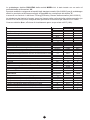
Description tinUeulaVretemaraP
k-Value k
Smart control compliance smart
Smart control factor SCF
Conversion coefficient CC
Ambient correction term Qcor kWh
Referenct energy QrefkWh
Useful energy content QH2O kWh
Correction ratio of reference and useful energy Qref/QH2O kWh
Daily electricity consumption (measured) Qtest_elec kWh
Water temperature at the beginning of the 24h measurement
cycle T3 ℃
Water temperature at the end of the 24h measurement cycle T5 ℃
Storage volume Mact kg
Storage volume Cact L
Daily electricity consumption (corrected) Qelec kWh
Water heating energy efficiency ηwh
Annual Electricity Consumption AEC kWh
Water heating energy efficiency class
Description Parameter Value Unit
Water temperature without tapping Tset ℃
Average water temperature of outlet warm water θ'p℃
Average water temperature of inlet cold water θc℃
Normalised value of the average temperature θp℃
Volume that delivered water of at least 40 V40exp L
Calculated volume that delivered hot water of at least 40 V40 L
68.0
60.2
10.3
60.1
39.4
65.9
0.23
0
0
2.5
-0.480
5.845
6.689
0.874
7.705
59.7
60.8
45
45
6.682
36.03
1425
C
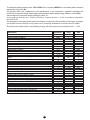
The electrical storage water heater D50-15FA2 of the company MIDEA Ltd. was tested with a declared
load profile of the size “M”
The product fulfills and corresponds to the requirements of the commission regulation standards (No
814/2013) for electrical storage water heater and achieved a water heating energy efficiency of ηwh=36%
that correspond to the water heating efficiency class “C”
In accordance with Annex Enercy Efficiency Classes article 1 of the commission regulation
(No 812/2013)
The evaluation of the result of this report with respect of conformity with the related commission regulation
(No 812/2013 and 814/2019) is only a part of the conformity assessment to achieve the ErP-Label.
Electricity consumption Qelec, water heating energy efficiency ηwh and mixed water at 40V 40
10

11
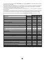
The electrical storage water heater D80-15FA2 of the company MIDEA Ltd. was tested with a declared
load profile of the size “M”
The product fulfills and corresponds to the requirements of the commission regulation standards (No
814/2013) for electrical storage water heater and achieved a water heating energy efficiency of ηwh=36%
that correspond to the water heating efficiency class “C”
In accordance with Annex Enercy Efficiency Classes article 1 of the commission regulation
(No 812/2013)
The evaluation of the result of this report with respect of conformity with the related commission regulation
(No 812/2013 and 814/2019) is only a part of the conformity assessment to achieve the ErP-Label.
Electricity consumption Qelec, water heating energy efficiency ηwh and mixed water at 40V 40
Description tinUeulaVretemaraP
k-Value k
Smart control compliance smart
Smart control factor SCF
Conversion coefficient CC
Ambient correction term Qcor kWh
Referenct energy QrefkWh
Useful energy content QH2O kWh
Correction ratio of reference and useful energy Qref/QH2O kWh
Daily electricity consumption (measured) Qtest_elec kWh
Water temperature at the beginning of the 24h measurement
cycle T3 ℃
Water temperature at the end of the 24h measurement cycle T5 ℃
Storage volume Mact kg
Storage volume Cact L
Daily electricity consumption (corrected) Qelec kWh
Water heating energy efficiency ηwh
Annual Electricity Consumption AEC kWh
Water heating energy efficiency class
Description Parameter Value Unit
Water temperature without tapping Tset ℃
Average water temperature of outlet warm water θ'p℃
Average water temperature of inlet cold water θc℃
Normalised value of the average temperature θp℃
Volume that delivered water of at least 40 V40exp L
Calculated volume that delivered hot water of at least 40 V40 L
0.23
0
0
2.5
-0.425
5.845
5.946
0.983
6.670
56.9
56.6
72
72
6.581
36.46
1408
C
62
61.2
10.3
61.2
59
100

12
0.23
0
0
2.5
-0.396
5.845
5.794
1.009
6.909
54
57.8
90
90
6.533
36.68
1400
C
58
60.6
10.2
60.6
66
111
Description tinUeulaVretemaraP
k-Value k
Smart control compliance smart
Smart control factor SCF
Conversion coefficient CC
Ambient correction term Qcor kWh
Referenct energy QrefkWh
Useful energy content QH2O kWh
Correction ratio of reference and useful energy Qref/QH2O kWh
Daily electricity consumption (measured) Qtest_elec kWh
Water temperature at the beginning of the 24h measurement
cycle T3 ℃
Water temperature at the end of the 24h measurement cycle T5 ℃
Storage volume Mact kg
Storage volume Cact L
Daily electricity consumption (corrected) Qelec kWh
Water heating energy efficiency ηwh
Annual Electricity Consumption AEC kWh
Water heating energy efficiency class
Description Parameter Value Unit
Water temperature without tapping Tset ℃
Average water temperature of outlet warm water θ'p℃
Average water temperature of inlet cold water θc℃
Normalised value of the average temperature θp℃
Volume that delivered water of at least 40 V40exp L
Calculated volume that delivered hot water of at least 40 V40 L
The electrical storage water heater D100-15FA2 of the company MIDEA Ltd. was tested with a declared
load profile of the size “M”
The product fulfills and corresponds to the requirements of the commission regulation standards (No
814/2013) for electrical storage water heater and achieved a water heating energy efficiency of ηwh=36%
that correspond to the water heating efficiency class “C”
In accordance with Annex Enercy Efficiency Classes article 1 of the commission regulation
(No 812/2013)
The evaluation of the result of this report with respect of conformity with the related commission regulation
(No 812/2013 and 814/2019) is only a part of the conformity assessment to achieve the ErP-Label.
Electricity consumption Qelec, water heating energy efficiency ηwh and mixed water at 40V 40

www.midea.com/global
The product is subject to change without notice.
Please keep this manual properly.
Midea Italia S.r.l.
A Socio Unico Viale
Bodio 29 20158 Milano
(MI) www.midea.com/it

Il diagramma sopra è solo per riferimento. Si prega di considerare come
standard l'apparenza del prodotto concreto.
Scaldabagno elettrico
Manuale Utente e di installazione
Modello D30-15FA2
D50-15FA2
D80-15FA2
D100-15FA2
I disegni e le informazioni grafiche contenute in questo volume
sono solo indicative. L'aspetto effettivo di prodotti e accessori
può differire da quanto indicato

Indicazioni generali
●
autorizzati.
●Il produttore non deve essere ritenuto responsabile per qualsiasi danno o malfunzionamento
causato da installazione errata o dal mancato rispetto delle istruzioni incluse in questo libretto.
●Per delle linee guida su installazione e manutenzione più dettagliate, fare riferimento ai capitoli
sotto.
TABELLA DEI CONTENUTI
TITOLO Pagina
1. Precauzoni........................................................................................................................................(2)
2. Introduzione prodotto........................................................................................................................(3)
3. Installazione unità ............................................................................................................................ (5)
4. Metodi di utilizzo ..............................................................................................................................(7)
5. Manutenzione ..................................................................................................................................(7)
6. Risoluzione problemi ........................................................................................................................(8)
7. INFORMAZIONI PRODOTTO CON NORMATIVA UE ..................................................................... (9)
1

Prima di installare questo scaldabagno, verificare che l'alimentazione elettrica sia correttamente
connessa e che la connessione di messa a terra sia adeguata. In caso contrario, lo scaldabagno
non può essere installato e utilizzato. Non utilizzare prolunghe. l'installazione e utilizzo non
corretto di questo scaldabagno può causare lesioni serie e perdita della proprietà.
Avvertenze speciali
●La presa deve disporre di messa a terra sicura. La corrente nominale della presa non deve
essere inferiore a 10A. La presa e la spina devono essere tenute asciutte per evitare cortocircuiti.
Ispezionare frequentemente che la spina sia in ben in contatto con la presa. Ispezionare come
segue: inserire la spina nella presa, dopo mezz'ora di utilizzo, spegnere l'unità, staccare la spina, e
verificare se è calda. Se è troppo calda (oltre 50°C), cambiare la presa per evitare di danneggiar
la spina, causare incendi o altri incidenti personali causati da contatti malfunzionanti.
●La presa di corrente non deve essere installata ad un'altezza inferiore a 1,8m.
●La parete in cui deve essere installato lo scaldabagno elettrico deve poter sorreggere più di due
volte del peso dell'elettrodomestico completamente pieno d'acqua senza piegarsi o formare crepe.
In caso contrario, è necessario adottare delle misure di rafforzamento.
●La valvola di rilascio pressione collegata allo scaldabagno deve essere installata nell'entrata
dell'acqua fredda, ed è necessario assicurarsi che non sia esposta a vapore. Potrebbe fuoriuscire
dell'acqua dalla valvola di rilascio pressione, per cui il tubo di uscita deve essere aperto all'aria; la
valvola di rilascio pressione deve essere controllata e pulita regolarmente, assicurandosi che non
sia ostruita.
Acqua
calda
Valvola di rilascio
pressione
Acqua fredda
Maniglia di scarico
Foro di rilascio pressione
(Fig.1)
●Al primo utilizzo dello scaldabagno (o al primo utilizzo dopo la manutenzione), questo non può
delle valvole di uscita dello scaldabagno deve essere aperta per favorire l'uscita di aria. Questa
valvola può essere chiusa dopo che lo scaldabagno è stato completamento riempito d'acqua.
●Lo scaldabagno non è destinato a utilizzo da parte di persone (inclusi bambini) con capacità
motorie, sensoriali o mentali ridotte, o mancanza di competenza o esperienza, a meno che
supervisionati o guidati all'uso dell'elettrodomestico da una persona responsabile per la loro
sicurezza. Tenere sotto controllo i bambini per assicurarsi che non giochino con lo scaldabagno.
1. PRECAUZIONI
2

2
●
●
●
●
●
●
●
●
Durante il riscaldamento, potrebbero cadere delle gocce d'acqua dal foro di rilascio pressione
della valvola. Questo è un fenomeno normale. Nel caso in cui si verifichi una perdita
consistentedi acqua, contattare il centro di supporto clienti per richiedere la riparazione. Il
foro di rilascio pressione non deve essere mai ostruito, altrimenti, lo scaldabagno potrebbe
danneggiarsi, provocando eventualmente degli incidenti.
Il tubo di scarico connesso al foro di rilascio pressione deve essere tenuto in pendenza verso il basso.
Dato che la temperatura dell'acqua all'interno dello scaldabagno può raggiungere fino a 75°C,fare
entrare l'acqua in contatto con il corpo umano senza predisporre un miscelatore o una
valvola termostatica. Regolare la temperatura dell'acqua fino aun valore adatto per evitare
scottature.
Ruotare la vite filettata della valvola di rilascio pressione e sollevare il manico di scarico
verso l'alto.(Vedere fig.1) per scaricare l'acqua dal contenitore interno
Se il cavo elettrico è danneggiato, questo deve essere sostituito da personale
dimanutenzione certificato dal produttore
Se altre parti o componenti di questo scaldabagno sono danneggiate, contattare il centro di
supporto clienti per richiedere la riparazione.
Questo apparecchio non è destinato all'uso da parte di persone (compresi i bambini) con
ridotte capacità fisiche, sensoriali o mentali o mancanza di esperienza e conoscenza, a
meno che nonsiano state sottoposte a supervisione o istruzione relative all'uso
dell'elettrodomestico da parte di una persona responsabile della loro sicurezza.
I bambini devono essere costantemente sorvegliati per assicurarsi che non giochino con l'apparecchio.
28
47
74
93
2. INTRODUZIONE PRODOTTO
2.1 Parametri prestazioni tecniche
Modello Volume
(L)
Potenza
nominale
(W)
Tensione
nominale
(ACV)
Pressione
nominale
(MPa)
Temperatura
acqua massima
(°C)
Classe di
protezione
Classe di
impermeabilità
D30-15FA2 1500 220-240 0,8
0,8
0,8
0,8
75 I IPX4
D50-15FA2 1500 220-240 75 I IPX4
D80-15FA2 1500 220-240 75 I IPX4
D100-15FA2 1500 220-240 75 I IPX4
2.2 Breve introduzione della struttura del prodotto
C
B
A
D
Contenitore interno
Isolante termico
Elemento riscaldante
Anodo-
Uscita acqua calda
Guscio
Termometro
opzionale
Indicatore di riscaldamento
Ingresso acqua fredda
3

4
D30-15FA2 D50-15FA2 D80-15FA2 D100-15FA
A 340 385 450 450
B 570 705 758 908
C 100 100 100 100
D 200 200 200 200
(Nota: tutte le dimensioni sono in mm)
2.3 Diagramma cavi interni
Protezione
termica Termostato
Marrone
L
N
E
Blu
Giallo/Verde
SCHEMA ELETTRICO
Elemento riscaldante
Indicatore riscaldamento

5
3. INSTALLAZIONE UNITÀ
3.1 Istruzioni installazione
Questo scaldabagno deve essere installato su una parete solida. Se la parete non è in grado
di sorreggere più di due volte del peso dell'elettrodomestico completamente pieno d'acqua, è
necessario installare un supporto speciale.
Nel caso in cui la parete sia in mattoni forati, assicurarsi di riempirli di cemento completamente.
Dopo aver selezionato la posizione adeguata, determinare i punti dei due fori di installazione
prodotto selezionato). Realizzare due fori sulla parete delle profondità corrispondente utilizzando
un trapano delle stesse dimensioni dei tasselli a espansione collegati al dispositivo, inserire le
vite, ruotare i ganci verso l'alto, stringere i bulloni fermamene e successivamente appendere lo
Tassello a espansione
(con gancio)
(Fig.2)
Installare la presa di corrente sulla parete. I requisiti della presa sono i seguenti: 250V/10A, fase
singola, tre POLI. Si consiglia di posizionare la presa sul lato destro sopra lo scaldabagno. La
di effettuare l'operazione in sicurezza.
L (marrone) E (giallo/verde)
N (blu)
Messa a terra (Fig.3)
≥1,8m
Se il bagno è troppo piccolo, lo scaldabagno può essere installato in un’altra stanza al riparo da
deve essere il più vicino possibile al bagno.
3.2 Collegamento tubi
Ogni parte di tubo ha dimensione G1/2”; la pressione massima di entrata deve essere regolata in
Pa; la pressione minima di entrata deve essere regolata in Pa.
Collegare la valvola di rilascio pressione con l’entrata dello scaldabagno.
Per evitare perdite, durante il collegamento dei tubi è necessario aggiungere le guarnizioni in
gomma ermetiche fornite con lo scaldabagno in ogni parte terminale, in modo da realizzare dei
La pagina si sta caricando...
La pagina si sta caricando...
La pagina si sta caricando...
La pagina si sta caricando...
La pagina si sta caricando...
La pagina si sta caricando...
La pagina si sta caricando...
La pagina si sta caricando...
-
 1
1
-
 2
2
-
 3
3
-
 4
4
-
 5
5
-
 6
6
-
 7
7
-
 8
8
-
 9
9
-
 10
10
-
 11
11
-
 12
12
-
 13
13
-
 14
14
-
 15
15
-
 16
16
-
 17
17
-
 18
18
-
 19
19
-
 20
20
-
 21
21
-
 22
22
-
 23
23
-
 24
24
-
 25
25
-
 26
26
-
 27
27
-
 28
28


