
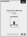
Storage Electric Water Heater
The diagram above is just for reference. Please take the
appearance of the actual product as the standard.
Instruction Manual
For Model: D50-15ED2
D80-15ED2
D100-15ED2
Thank you very much for purchasing our water heater.
Before installing and operating your water heater, please
read this manual carefully and keep it for future reference.

1
The installation and maintenance has to be carried out by qualified professionals or Midea
authorized technicians.
The manufacturer shall not be held responsible for any damage or malfunction caused by wrong
installation or failing to comply with following instructions included in this pamphlet.
For more detailed installation and maintenance guidelines, please refer to below chapters.
TABLE OF CONTENTS
TITLE PAGE
1.Cautions ...........................................................................................................................(2)
2.Product introduction .........................................................................................................(3)
3.Unit installation .................................................................................................................(5)
4.Methods of using ..............................................................................................................(7)
5.Maintenance.....................................................................................................................(9)
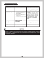
6.Troubleshooting..............................................................................................................(10)
7.Produce information with EU regulation ......................................................................... (11)
●
●
●
General Remark

2
The supply socket must be earthed reliably. The rated current of the socket shall not be lower than
10A. The socket and plug shall be kept dry to prevent electrical leakage.
The installation height of the supply socket shall not be lower than 1.8m.
The wall in which the electrical water heater is installed shall be able to bear the load more than two
times of the heater filled fully with water without distortion and cracks. Otherwise, other strengthen-
ing measures shall be adopted.
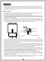
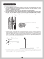
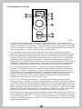
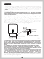
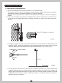
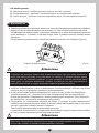
The pressure relief valve attached with the heater must be installed at the cold water inlet of this
heater(see Fig.1), and make sure it is not exposed in the foggy. The water may be outflowed from
pressure relief valve, so the outflow pipe must open wide in the air; The pressure relief valve need
to be checked and cleaned regularly, so as to make sure it will not be blocked.
Before installing this water heater,check and confirm that the earthing on the supply socket is
reliably grounded. Otherwise, the electrical water heater can not be installed and used. Do not use
extension boards. Incorrect installation and use of this electrical water heater may result in serious
injuries and loss of property.
Special Cautions
Hot water
1. CAUTIONS
●
●
●
●
●
●
●
●
●
●
Cold water (Fig.1)
Pressure relief valve
Thread screw
Drain handle
Pressure release hole
When using the heater for the first time(or the first use after maintenance), the heater can not be
switched on until it has been filled fully with water. When filling the water, at least one of the outlet
valves at the outlet of the heater must be opened to exhaust the air. This valve can be closed after
the heater has been filled fully with water.
The water heater is not intended for use by persons(including children)with reduced physical,
sensory or mental capabilities, or lack of experience and knowledge, unless they have been given
supervision or instructions concerning use of the appliance by a person responsible for their safety.
Children should be supervised to ensure that they do not play with the heater.
During heating, there may be drops of water dripping from the pressure release hole of the
pressure relief valve. This is a normal phenomenon. If there is a large amount of water leak, please
contact customer care center for repair. This pressure release hole shall, under no circumstances,
be blocked; otherwise, the heater may be damaged, even resulting in accidents.
The drainage pipe connected to the pressure release hole must be kept sloping downwards.
Since the water temperature inside the heater can reach up to 75, the hot water must not be
exposed to human bodies when it is initially used. Adjust the water temperature to a suitable
temperature to avoid scalding.
If the flexible power supply cord is damaged, the special supply cord provided by the manufacturer
must be selected, and replaced by the professional maintenance personnel.

3
2. PRODUCT INTRODUCTION
2.1 Nomenclature
D -
NOTE
This manual is applicable to the storage electric water heaters (D *-***) manufactured by
this company.
is the product code of the storage electric water heater;
is the capacity (L);
represents the rated power (*100W);
represents the pattern code (eg : A,B,C...);
represents the extension of pattern (eg : 1,2,3...);
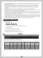
2.2 Technical Performance Parameters
●
●
●
●
●
●
If any parts and components of this electrical water heater are damaged please contact customer
care center for repair.
This appliance is not intended for use by persons (including children) with reduced physical,
sensory or mental capabilities, or lack of experience and knowledge, unless they have been
given supervision or instruction concerning use of the appliance by a person responsible for
their safety.
Children should be supervised to ensure that they do not play with the appliance.
The maximum inlet water pressure is 0.5MPa; the minimum inlet water pressure is 0.1MPa, if this
is necessary for the correct operation of the appliance.
The water may drip from the discharge pipe of the pressure-relief device and that this pipe must
be left open to the atmosphere; The pressure-relief device is to be operated regularly to remove
lime deposits and to verify that it is not blocked.
In order to drain away the water inside the inner container, it can be drained away from the
pressure release valve. Twist the thread screw of the pressure release valve off, and lift the drain
handle upwards.(See Fig.1) A discharge pipe connected to the pressure-relief device is to be
installed in a continuously downward direction and in a frost-free environment.
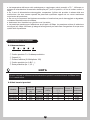
Model
Rated
Voltage
(ACV)
IPX4
IPX4
IPX4
75
75
75
0.8
0.8
0.8
0.8
220-240
220-240
220-240
220-240
1500
1500
1500
28
47
74
D30-15ED2
D50-15ED2
D80-15ED2
Rated
Power
(W)
Volume
(L)
Rated
Pressure
(MPa)
Max Of Water
Temperature
(°C)
Protection
Class
Waterproof
Grade
I
I
I
IPX4751500
93
D100-15ED2 I

4
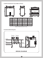
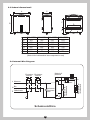
2.3 Brief introduction of product structure
2.4 Internal Wire Diagram
WIRING DIAGRAM
(Note:All dimensions are in mm)
Thermal
Cut Out
Thermal
Cut Out
Power
Indicator
Heating Indicator
Thermostat
Thermostat
Heating Element
Power
Brown
Blue
Yellow/Green
E
N
L
Q Q
01
2
1
0
2
Q
Q
B
AC
D
E
F
A
B
C
D
E
F
D30-20ED2 D50-20ED2 D80-20ED2 D100-20ED2
355 355
302 470
250
575
470
250
860
470
183 183
415
365
300
900
570
265
415
550
300
1090
570
265

3. UNIT INSTALLATION
3.1 Installation Instruction
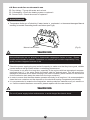
This electrical water heater shall be installed on a solid wall. If the strength of the wall cannot
bear the load equal to two times of the total weight of the heater filled fully with water, it is then
necessary to install a special support.
Incase of hollow bricks wall, ensure to fill it with cement concrete completely.
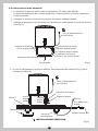
After selecting a proper location, determine the positons of the two install holes used for expan-
sion bolts with hook, Make two holes in the wall with the corresponding depth by using a
chopping bit with the size matching the expansion bolts attached with the machine, insert the
screws, make the hook upwards, tighten the nuts to fix firmly, and then hang the electrical
water heater on it (see Fig.2).
Install the supply socket in the wall. The requirements for the socket are as follows: 250V/10A,
single phase, three electrodes. It is recommended to placed the socket on the right above the
heater. The height of the socket to the ground shall not be less than 1.8m (see Fig.3).If there
is fault on power cable, it should be replaced by the manufacturers, agencies or qualified person
who is able to do this so as to ensure the safety.
If the bathroom is too small, the heater can be installed at another place. However, in order
to reduce the pipeline heat losses, the installation position of the heater shall be closed to the
location shall be as near as possible to the heater.
(Fig.2)
(Fig.3)
Expansion bolt (with hook)
N (Blue)
Ground
≥1.8m
L (Brown) E (Yellow/Green)

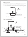
3.2 Pipelines Connection
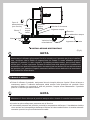
If the users want to realize a multi-way supply system, refer to the method shown in fig.5 and
fig.6 for connection of the pipelines.
5
6
The dimension of each pipe part is G1/2” ; The massive pressure of inlet should use Pa as
the unit; The minimum pressure of inlet should use Pa as the unit.
Connection of pressure relief valve with the heater on the inlet of the water heater.
In order to avoid leakage when connecting the pipelines, the rubber seal gaskets provided with
the heater must be added at the end of the threads to ensure leak proof joints (see Fig.4).
(Fig.4)
(Fig.5)
Pressure relief valve
Water inlet valve
Water inlet valve
Running water pipeMixing valve
Water pool
Triple joint Shower nozzle
Hot water outlet Cold water inlet
Rubber seal gaskets
Pressure relief valve
Pressure release hole
Joint screw for cold water inlet
Adjusting handle for
mixing valve
Hot
water
outlet
Cold
water
inlet
Hot water
Rubber seal gaskets
VERTICAL INSTALLATION
Power cord
Power cord

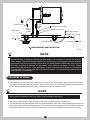
NOTE
Please be sure to use the accessories provided by our company to install this electric
water heater. This electric water heater can not be hung on the support until it has been
confirmed to be firm and reliable. Otherwise, the electric water heater may drop off from
the wall, resulting in damage of the heater, even serious accidents of injury. When
determining the locations of the bolt holes, it shall be ensured that there is a clearance
not less than 0.2m on the right side of the electric heater, to convenient the maintenance
of the heater, if necessary.
7
(Fig.6)
Pressure relief valve
Water inlet valve
Running water pipeMixing valve
Water pool
Triple joint
Water inlet valve
Shower nozzle
Hot
water
outlet
Cold
water
inlet
4. METHODS OF USING
NOTE
During normal operation, the inlet valve shall be always kept open.
First, open any one of the outlet valves at the outlet of the water heater, then, open the inlet valve.
The water heater gets filled with water. When water flows out of the outlet pipe it implies that the
heater has been filled fully with water, and the outlet valve can be closed.
Insert the supply plug into the supply socket, the indicator will light up this time.
The thermostat will automatically control the temperature. When the water temperature inside the
heater has reached the set temperature, it will switch off automatically, when the water tempera-
ture falls below the set point the heater will be turned on automatically to restore the heating.
●
●
●
HORIZONTAL INSTALLATION
Power cord

8
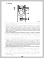
(Fig.7)
4.1 Operating Of The Unit
“2” is the on/off button, when press, water heater start working, display screen will be
lighted up. Then press again, electricty will be cut off, and display screen will be shut down.
"3" is for temperature adjustment knob with 360 °loop. Temperature increases by clockwise
rotation, and decreases if anticlockwise. During the rotation , display screen " 4" will change
accordingly. When temperature setting meets customers' requirements, stop rotating and
display screen "4" will flash for around 3 seconds, which means temperature has been setted
successfully. After flashing ,display screen "4" value will return to current inner water heater
temperature. After the smart control energy saving mode, the knob can not be adjusted.
“1” button is for selecting mode. When press firstly, display screen “4” will show the six
frequency option( index number “1” means 1500W for one tank, index number “2” means
1500W for dual tank , index number “3” means smart control energy saving mode, index
number “4” means ECO mode, index number “5” means high temperature bacteriostatic
mode, index number “6” means reservation hour setting mode).
"6" is for frequency display. If number " 1" comes out , it means 1500W(only one tank is
heating ) ; If number "2" comes out , it means 1500W (the two inner tank has been being
heated up ), If number " 3" comes out , it means smart control energy saving mode, the
water temperature is automatically changed. The appliance works to reduce the electricity
energy of the user consumption, which allows heat loss to be minimized and energy
savings to be maximized. This function is manually activated.The user can press the
POWER button three times to start the smart control.
From “5” &“7” &“8”(this horizontal strip ) , customer could tell heating status and WiFi
connection status . The light “5” will turn on when power is connected. The light “5“ will blink
, when smart control energy saving mode is started , According the temperature setted, the
light "7" will be shown in red which means water heater is being heated. When inner water
heater temperature reaches the setted value , light "7" will turns off , which means water
heater enter into warm-keeping status. Long press the on key for 3 seconds, and the WiFi
light starts to flash. After the connection is completed, the WiFi light is always on.
1
2
3
4
5
6
8
7
WIFI
POWER
"4" could show the current inner water temperature as well as setted temperature value.If no
person operates on water heater , the value in display screen " 4" means current emperature
value .By spinning knob "3" , "4" values will vary accordingly ( i.e temperature setting
process) , when finish temperature setting , "4" values will return back to actual current inner
water heater temperatrue.

5. MAINTENANCE
WARNING
Non-professionals are not allowed to disassemble temperature limiter to reset . Please
contact prefessionals to maintain. Otherwise our company will not take responsiblity if any
quality accident happens because of this
!
Check the power supply plug and socket frequently to make sure that they have good, reliable
contact and are well grounded without overheating phenomenon.
If the heater is not used for a long time, especially in the regions with low atmospheric tempera-
ture(lower than 0), the water inside the heater shall be drained away. This will prevent the
damage to the heater due to water freezing in the inner container, (Refer Cautions in this manual
for the method to drain away the water from the inner container).
In order to ensure that the water heater operates efficiently for a long time, it is recommended to
clean the inner container and the deposits on the electrical heating components periodically.
It is recommended to examine the magnesium anode protection materials every six months or
so. If all the material has been consumed, please replace with the new material.
●
●
●
●
WARNING
Do cut off power supply before maintenance, to avoid danger like electric shock.
!
9
4.2 Error code for serviceman’s use
E2: Dry Ashing---Top up with water and re-heat.
E3: Overheating---Check the heating system or replace it.
E4: Sensor Fault---Check the sensor or replace it.
Temperature limiter cut off electricty if water heater is overheated or thermostat damages.Manual
resetting is needed. Ressetting knob is as follows (see Fig.9).
●
(Fig.9)
Manual reset button

10
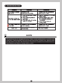
6. TROUBLESHOOTING
NOTE
This products are not equipped with plug. Please contact prefessionals to purchase and
install plug. Parts illustrated in this use and care manual are indicative only, parts provided
with the product may differ with illustrations.This product is intended for household use only.
Specifications are subject to change without notice.

11
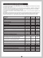
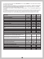
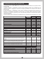
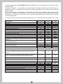
The electrical storage water heater D50-15ED2 of the company MIDEA Ltd. was tested with a declared
load profile of the size “M”
that correspond to the water heating efficiency class “B”
The product fulfills and corresponds to the requirements of the commission regulation standards (No
814/2013) for electrical storage water heater and achieved a water heating energy efficiency of
In accordance with Annex Enercy Efficiency Classes article 1 of the commission regulation (No
812/2013)
The evaluation of the result of this report with respect of conformity with the related commission regulation
(No 812/2013 and 814/2019) is only a part of the conformity assessment to achieve the ErP-Label.
Electricity consumption Qelec, water heating energy efficiency ηwh and mixed water at 40°C (V40).
ηwh=39%
Description Parameter Value Unit
k-Value k
Smart control compliance smart
Smart control factor SCF
Conversion coefficient CC
Ambient correction term Qcor
Referenct energy Qref
Useful energy content QH2O
Correction ratio of reference and useful energy Qref/QH2O
Daily electricity consumption (measured) Qtest_elec
Water temperature at the beginning of the 24h measurement
cycle T3
Water temperature at the end of the 24h measurement cycle T5
Storage volume Mact
Storage volume Cact
Daily electricity consumption (corrected) Qelec
Water heating energy efficiency ηwh
Annual Electricity Consumption AEC
Water heating energy efficiency class
Water temperature without tapping Tset
Average water temperature of inlet cold water θc
Normalised value of the average temperature θp
Calculated volume that delivered hot water of at least 40 V40
%
kWh
kWh
kWh
kWh
℃
℃
kg
L
kWh
kWh
kWh
kWh
kWh
kWh
℃
℃
℃
L
%
Sequence of SMART tapping cycles used during the test
Useful energy content of the hot water drawn-off during
smart period Qreference,H2O expressed in kWh:
Useful energy content of the hot water drawn-off during
smart period Qsmart,H2O expressed in kWh:
The weekly electricity consumption with smart controls
The weekly electricity consumption without smart controls
Qelec,week,smart
Qelec,week
Qreference,H2O
Qsmart,H2O
7. Produce information with EU regulation
0.23
1
23.2
2.5
-0.082
5.845
5.958
0.981
7.423
73.9
71.4
47
47
7.417
22.161
22.157
26.662
29.288
39.2
1309
B
73
10.4
72.6
75
M/S/M/S/M

12
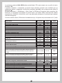
The electrical storage water heater D80-15ED2 of the company MIDEA Ltd. was tested with a declared
load profile of the size “M”
that correspond to the water heating efficiency class “B”
The product fulfills and corresponds to the requirements of the commission regulation standards (No
814/2013) for electrical storage water heater and achieved a water heating energy efficiency of
In accordance with Annex Enercy Efficiency Classes article 1 of the commission regulation (No
812/2013)
The evaluation of the result of this report with respect of conformity with the related commission regulation
(No 812/2013 and 814/2019) is only a part of the conformity assessment to achieve the ErP-Label.
Electricity consumption Qelec, water heating energy efficiency ηwh and mixed water at 40°C (V40).
ηwh=39%
Description Parameter Value Unit
k-Value k
Smart control compliance smart
Smart control factor SCF
Conversion coefficient CC
Ambient correction term Qcor
Referenct energy Qref
Useful energy content QH2O
Correction ratio of reference and useful energy Qref/QH2O
Daily electricity consumption (measured) Qtest_elec
Water temperature at the beginning of the 24h measurement
cycle T3
Water temperature at the end of the 24h measurement cycle T5
Storage volume Mact
Storage volume Cact
Daily electricity consumption (corrected) Qelec
Water heating energy efficiency ηwh
Annual Electricity Consumption AEC
Water heating energy efficiency class
Water temperature without tapping Tset
Average water temperature of inlet cold water θc
Normalised value of the average temperature θp
Calculated volume that delivered hot water of at least 40 V40
%
kWh
kWh
kWh
kWh
℃
℃
kg
L
kWh
kWh
kWh
kWh
kWh
kWh
℃
℃
℃
L
%
Sequence of SMART tapping cycles used during the test
Useful energy content of the hot water drawn-off during
smart period Qreference,H2O expressed in kWh:
Useful energy content of the hot water drawn-off during
smart period Qsmart,H2O expressed in kWh:
The weekly electricity consumption with smart controls
The weekly electricity consumption without smart controls
Qelec,week,smart
Qelec,week
Qreference,H2O
Qsmart,H2O
0.23
1
21.5
2.5
-0.107
5.845
5.958
0.981
7.803
74
71.9
74
74
7.781
22.157
22.156
28.364
31.426
39.0
1315
B
73
10.4
72.6
110
M/S/M/S/M

13
Description Parameter Value Unit
k-Value
Smart control compliance
Smart control factor
Conversion coefficient
Ambient correction term
Referenct energy
Useful energy content
Correction ratio of reference and useful energy
Daily electricity consumption (measured)
Water temperature at the beginning of the 24h measurement
cycle
Water temperature at the end of the 24h measurement cycle
Storage volume
Storage volume
Daily electricity consumption (corrected)
Water heating energy efficiency
Annual Electricity Consumption
Water heating energy efficiency class
Water temperature without tapping
Average water temperature of inlet cold water
Normalised value of the average temperature
Calculated volume that delivered hot water of at least 40
%
kWh
kWh
kWh
kWh
℃
℃
kg
L
kWh
kWh
kWh
kWh
kWh
kWh
℃
℃
℃
L
%
Sequence of SMART tapping cycles used during the test
Useful energy content of the hot water drawn-off during
smart period Qreference,H2O expressed in kWh:
Useful energy content of the hot water drawn-off during
smart period Qsmart,H2O expressed in kWh:
The weekly electricity consumption with smart controls
The weekly electricity consumption without smart controls
k
smart
SCF
CC
Qcor
Qref
QH2O
Qref/QH2O
Qtest_elec
T3
T5
Mact
Cact
Qelec
ηwh
AEC
Tset
θc
θp
V40
Qelec,week,smart
Qelec,week
Qreference,H2O
Qsmart,H2O
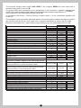
The electrical storage water heater D100-15ED2 of the company MIDEA Ltd. was tested with a
declared load profile of the size “M”
that correspond to the water heating efficiency class “B”
The product fulfills and corresponds to the requirements of the commission regulation standards (No
814/2013) for electrical storage water heater and achieved a water heating energy efficiency of
In accordance with Annex Enercy Efficiency Classes article 1 of the commission regulation (No
812/2013)
The evaluation of the result of this report with respect of conformity with the related commission regulation
(No 812/2013 and 814/2019) is only a part of the conformity assessment to achieve the ErP-Label.
Electricity consumption Qelec, water heating energy efficiency ηwh and mixed water at 40°C (V40).
ηwh=41%
0.23
1
15.82
2.5
-0.02278
5.845
5.958
0.981
6.5851
73.3
72.8
92
92.1
6.765
22.127
22.100
25.529
27.832
40.8
1258
B
73
10.4
68.2
131
M/S/M/S/M

www.midea.com/global
The product is subject to change without notice.
Please keep this manual properly.
Midea Italia S.r.l. a socio unico:
Viale Luigi Bodio 29/37
20158 Milano Italia
midea.com/it

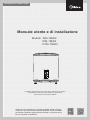
Storage Electric Water Heater
L'immagine sopra indicativa e ha il solo scopo di descrivere il prodotto.
Considerare le informazioni del manuale e le specifiche di
riferimento per le informazioni effettive.
Manuale utente e di installazione
Modelli: D50-15ED2
D80-15ED2
D100-15ED2
Grazie per aver acquistato uno scaldacqua Midea! Questo prodotto
conforme ai pi elevati standard di qualit disponibili. Prima di installare
ed utilizzare il prodotto, leggere questo manuale e conservarlo per le
future necessit di consultazione.

1
Titolo Pagina
1.Precauzioni.......................................................................................................................(2)
2.Introduzione al prodotto....................................................................................................(3)
3.Installazione dell’unit ........................................................................................................(5)
4.Metodi di utilizzo ..............................................................................................................(7)
5.Manutenzione...................................................................................................................(9)
6.Risoluzione dei problemi ................................................................................................(10)
7.Informazioni sul prodotto in merito alle normative EU.................................................... (11)
●
●
●
L'installazione e la manutenzione del prodotto devono essere effettuate da personale qualificato
o da centri assistenza tecnica autorizzati da Midea.
Il produttore non deve essere ritenuto responsabile per qualsiasi danno o malfunzionamento
causato da installazione errata o dal mancato rispetto delle istruzioni incluse in questo libretto.
Per maggiori informazioni sulle condizioni di installazione e manutenzione dei prodotti, fare
riferimento a quanto segue.
Indicazioni generali
TABLE OF CONTENTS

2
● La presa di alimentazione deve essere collegata alla messa a terra. La corrente nominale della
presa non deve essere inferiore a 10A. La presa e la spina non devono venire in contatto con liquidi
o vapore per evitare cortocircuiti.
● La presa non deve essere posizionata ad un’altezza dal suolo inferiore a 1.8m.
● La parete in cui deve essere installato lo scaldabagno elettrico deve poter sorreggere il doppio
del peso dell'elettrodomestico completamente pieno d'acqua senza deformazioni o crepe.
In caso contrario, necessario adottare delle misure di rinforzo della parete.
● La valvola di sicurezza collegata allo scaldabagno deve essere installata in prossimit della presa
di ingresso dell'acqua fredda. Assicurarsi che la valvola non sia non sia esposta a vapore.
Il prodotto pu essere svuotato mediante lo scarico della valvola di sicurezza: agire sulla leva per
aprire la valvola e consentire lo scarico dell'acqua (Vedi Fig. 1)., rivolta verso il basso e deve
essere previsto un sistema di scarico che non sia soggetto a congelamento.
Prima di installare questo scaldabagno, verificare che l'alimentazione elettrica sia correttamente
connessa e che il collegamento di messa a terra sia adeguato. In caso contrario, lo scaldabagno
non pu essere installato e utilizzato. Non utilizzare prolunghe. La non corretta installazione e lo
scorretto utilizzo di questo scaldabagno possono essere causa di lesioni e danni materiali alle
propriet.
Avvertenze speciali
Hot water
1. Precauzioni
Cold water (Fig.1)
Pressure relief valve
Thread screw
Drain handle
Pressure release hole
● In corrispondenza del primo avviamento del prodotto o dopo un'attivit di manutenzione, l'apparec-
chio non pu essere attivato se non completamente riempito di acqua. Durante il riempimento, il
rubinetto dell'acqua calda deve essere mantenuto costantemente aperto per far fuoriuscire l'aria
dal prodotto. Chiudere il rubinetto quando il prodotto pieno di acqua e procedere all'accensione
dell'unit.
● Lo scaldabagno non destinato all'utilizzo da parte di persone (inclusi bambini) con capacit
motorie, sensoriali o mentali ridotte, o mancanza di competenza o esperienza, a meno che non
siano supervisionati o guidati nell'uso dell'elettrodomestico da una persona responsabile per la loro
sicurezza. Assicurarsi che i bambini non giochino con lo scaldabagno.
● Durante il riscaldamento dell'acqua possibile che alcune gocce di acqua fuoriescano dalla valvola
di sicurezza: Questo fenomeno normale. Se la quantit dell’acqua espulsa maggiore ad alcune
gocce, contattare un centro assistenza tecnica autorizzato dal produttore o il rivenditore. Non
ostruire mai, per nessun motivo il condotto di scarico; se il condotto di scarico ostruito, si possono
determinare gravi danni o incidenti con possibili danni a cose o persone.
● Lo scarico dell’acqua deve essere rivolto verso il basso e deve essere previsto un sistema di
scarico che non sia soggetto a congelamento.

3
2. Introduzione al prodotto
2.1 Nomenclatura
D -
NOTA
Questo manuale si riferosce esclusivamente ai prodotti commercializzati da Midea Italia
S.r.l. a socio unico.
Codice prodotto: D = Scaldacqua elettrico
Capacit (L)
Potenza elettrica (W Moltiplicato 100)
Codice prodotto (es: A,B,C...);
Serie produttiva (es: 1,2,3...)
Modello
Tensione
Nominale
(VAC)
IPX4
IPX4
IPX4
75
75
75
0.8
0.8
0.8
0.8
220-240
220-240
220-240
1500
1500
1500
28
47
74
D30-15ED2
D50-15ED2
D80-15ED2
D100-15ED2
Potenza
Nominale
(W)
Volume
(L)
Pressione
(MPa)
Temperatura
(℃)
Grado di
protezione
2.2 Dati tecnici prodotti
I
I
I
● La temperatura dell'acqua nello scaldacqua pu raggiungere valori prossimi a 75. Utilizzare un
sistema di miscelazione termostatica dell'acqua per i punti di prelievo, al fine di evitare ustioni e
ferite.
● Se il cavo di alimentazione danneggiato, sospendere l’utilizzo del prodotto in attesa della sua
sostituzione che dovr essere operata da personale qualificato oppure da un centro assistenza
autorizzato dal produttore.
● Se una o pi componenti del sistema necessitano di sostituzione perch danneggiate o degradate,
contattare l'assistenza tecnica Midea.
● Assicurarsi che I bambini non giochino con il prodotto.
● La pressione massima per l'adduzione acqua pari a 0.5Mpa. La pressione minima di adduzione
acqua pari a 0.1Mpa. Utilizzare gli adeguati accorgimenti per assicurare l'erogazione di acqua entro
questi limiti di pressione.
IPX475
220-2401500
93 I
Classe di
protezione

B
AC
D
E
F
4
2.3 Schemi dimensionali
(Nota: tutte le dimensioni sono espresse in mm)
2.4 Internal Wire Diagram
Schema elettrico
Protettore
Termico
Protettore
Termico
Indicatore
Presenza
Rete
Indicatore di
riscaldamento
Termostato
Termostato
Resistenza di
riscaldamento
Modulo di
potenza
Marrone
Blu
Giallo/Verde
E
N
L
Q Q
01
2
1
0
2
Q
Q
A
B
C
D
E
F
D30-20ED2 D50-20ED2 D80-20ED2 D100-20ED2
355 355
302 470
250
575
470
250
860
470
183 183
415
365
300
900
570
265
415
550
300
1090
570
265
La pagina si sta caricando...
La pagina si sta caricando...
La pagina si sta caricando...
La pagina si sta caricando...
La pagina si sta caricando...
La pagina si sta caricando...
La pagina si sta caricando...
La pagina si sta caricando...
La pagina si sta caricando...
La pagina si sta caricando...
-
 1
1
-
 2
2
-
 3
3
-
 4
4
-
 5
5
-
 6
6
-
 7
7
-
 8
8
-
 9
9
-
 10
10
-
 11
11
-
 12
12
-
 13
13
-
 14
14
-
 15
15
-
 16
16
-
 17
17
-
 18
18
-
 19
19
-
 20
20
-
 21
21
-
 22
22
-
 23
23
-
 24
24
-
 25
25
-
 26
26
-
 27
27
-
 28
28
-
 29
29
-
 30
30


in altre lingue
- English: Midea D50-15ED2 User manual
Documenti correlati
Altri documenti
-
Comfee D10, 15, 30 Series Storage Electric Water Heater Manuale utente
-
Comfee D10-15VEO Manuale utente
-
Thermex HIT-Pro / HIT-Eco Manuale del proprietario
-
Samsung AE260RNWSEG/EU Manuale utente
-
Samsung MIM-E03AN Guida utente
-
Panasonic PAWDHWM300AE Manuale del proprietario
-
Sime ESTELLE HE 4 ErP Manuale utente
-
-
Ariston Classico4528 Manuale utente
-
Ariston ABS VLS EVO WI-FI 80 Manuale utente