Optika B-383LD1 Manuale utente
- Categoria
- Microscopi
- Tipo
- Manuale utente
Questo manuale è adatto anche per

Version: 2
Issued: 18, 03, 2015
Model
B-383LD1
B-383LD2
B-380 Series
INSTRUCTION MANUAL

Page 2
Table of Contents
Warning
Symbols and conventions
Safety Information
Intended use
Package Contents
Unpacking
Product specications
Overview
Using the microscope
Using the uorescence
Maintenance
Troubleshooting
User replaceable accessories and spare parts
Equipment disposal

Page 3
Warning
This microscope is a scientic precision instrument designed to last for many years with a minimum of mainte-
nance. It is built to high optical and mechanical standards and to withstand daily use.
We remind you that this manual contains important information on safety and maintenance, and that it must
therefore be made accessible to the instrument users.
We decline any responsibility deriving from incorrect instrument use uses that does not comply with this manual.
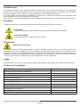
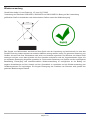
Symbols and conventions
The following chart is an illustrated glossary of the symbols that are used in this manual.
CAUTION
This symbol indicates a potential risk and alerts you to proceed with caution.
ELECTRICAL SHOCK
This symbol indicates a risk of electrical shock.
Safety Information
Avoiding Electrical Shock
Before plugging in the power supply, make sure that the supplying voltage of your region matches with the op-
eration voltage of the equipment and that the lamp switch is in off position.
Users should observe all safety regulations of the region. The equipment has acquired the CE safety label.
However, users have full responsibility to use this equipment safely.
Please follow the guidelines below, and read this manual in its entirety to ensure safe operation of the unit.
Intended use
For research and teaching use only. Not intended for any animal or human therapeutic or diagnostic use.
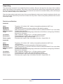
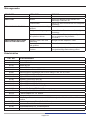
Package Contents
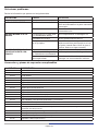
DESCRIPTION QUANTITY
Microscope stand with nosepiece, stage, condenser 1
Optical head (trinocular) 1
Objective E-PLAN IOS 4x 1
Objective E-PLAN IOS 10x 1
Objective E-PLAN IOS 20x 1
Objective E-PLAN IOS 40x 1
Objective PLAN IOS MET 50x 1
Eyepiece WF10x/20mm 2
Fluorescence attachment 1
Dust cover 1
Power supply output 6Vdc 1

Page 4
Unpacking
The microscope is housed in a moulded Styrofoam container. Remove the tape from the edge of the container
and lift the top half of the container. Take some care to avoid that the optical items (objectives and eyepieces)
fall out and get damaged. Using both hands (one around the arm and one around the base), lift the microscope
from the container and put it on a stable desk.
Place the observation head onto the top of the arm and tighten the lock-screw. Insert the eyepieces into the eye
tubes and x them with the tiny screws on the side of the eye tubes. Remove the plastic protection lm from the
microscope stage.
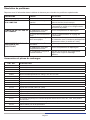
Product specications
B-383LD1
Head: Trinocular, 30° inclined, 360° rotating. Interpupillary adjustment 48-75 mm.
Eyepieces: WF10X/20mm.
Nosepiece: 5 position on reversed revolving nosepiece. Ball bearing rotation.
Objectives: IOS E-PLAN 4x/0.10, 10x/0.25, 20x/0.40, 40x/0.65, and PLAN 50x/0.75 (no cover slide).
Focusing system: Coaxial coarse and fine..
Stage: Double layer mechanical sliding stage, dimensions 216x150mm, moving range 78x54mm.
Belt-drive in X direction.
Condenser: Abbe condenser, sliding-in, N.A. 1.25 with centering system.
Illumination: Transmitted light: X-LED
3
, with manual brightness control.
Epi-fluorescence: high-power blue LED.
Power supply: External power supply: Input 100-240Vac 50-60Hz / Output 6Vdc 1A.
B-383LD2
Head: Trinocular, 30° inclined, 360° rotating. Interpupillary adjustment 48-75 mm.
Eyepieces: WF10X/20mm.
Nosepiece: 5-position reversed revolving nosepiece. Ball bearing rotation.
Objectives: IOS E-PLAN 4x/0.10, 10x/0.25, 20x/0.40, 40x/0.65, and PLAN 50x/0.75 (no cover slide).
Focusing system: Coaxial coarse and fine.
Stage: Double layer mechanical sliding stage, dimensions 216x150mm, moving range 78x54mm.
Belt-drive in X direction.
Condenser: Abbe condenser, sliding-in, N.A. 1.25 with centering system.
Illumination: Transmitted light: X-LED
3
, with manual brightness control.
Epi-fluorescence: high-power white LED (for B ang G filtersets).
Power supply: External power supply: Input 100-240Vac 50-60Hz / Output 6Vdc 1A.

Page 5
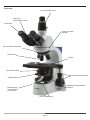
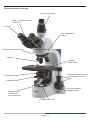
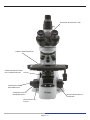
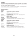
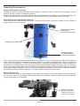
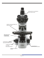
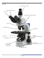
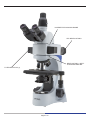
Overview
PHOTO/VIDEO PORT
HEAD LOCKING
SCREW
REVOLVING NOSEPIECE
STAGE
TRANSLATION KNOBS
BRIGHTNESS
ADJUSTMENT
(LEFT SIDE)
CONDENSER CENTERING
SCREWS
IRIS DIAPHRAGM
EYEPIECE
CONDENSER
LED ILLUMINATOR
OBJECTIVE
DIOPTRIC
ADJUSTMENT RING

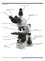
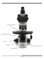
Page 6
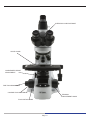
SLIDE CLAMP
FINE FOCUSING KNOB
CONDENSER HEIGHT
ADJUSTMENT
TENSION
ADJUSTMENT KNOB
COARSE FOCUSING KNOB
FOCUS STOP KNOB
INTERPUPILLARY DISTANCE

Page 7
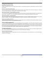
Using the microscope
Adjust the observation head
Loosen the lock-screw, turn the observation head to a comfortable position for observation, and then lock the
lock-screw.
Place the specimen on the stage
Lock the specimen slide on the mechanical stage using the slide clamp. Ensure that the specimen is centred
over the stage opening by adjusting the coaxial knobs of the stage
LED lamp settings – Transmitted illumination
The microscope is tted with high brightness white LED illuminator. Press the selector switch on the back of the
main body to I position. Turn the brightness adjustment knob to a brightness suitable for observation.
LED lamp settings – Epillumination
The microscope is tted with high brightness LED illuminator. Press the selector switch on the back of the main
body to II position. Turn the brightness adjustment knob to a brightness suitable for observation.
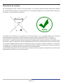
Adjust interpupillary distance
Hold the right and left parts of the observation head by both hands and adjust the interpupillary distance by turn-
ing the two parts until one circle of light can be seen.
Focus and diopter adjustment
Turn the dioptric adjustment ring on the left eyepiece to the zero position. Turn the coarse focus knob in order
to focus the slide with an objective with low magnication. Adjust the ne focus knob until you obtain a clear and
dened picture observing with the right eye, and then act on the left dioptric compensation ring observing with
the left eye. When the image appears in focus, choose the necessary objective with the revolving nosepiece.
Turn the tension-adjust-knob to get a suitable tension for the focus system.
Condenser adjustment
Turn the condenser adjustment knob to move the condenser up or down for a clear and uniform sample illumina-
tion. The two condenser centring screws can be used to centre the condenser.
Set the numerical aperture
Adjust the aperture of the iris diaphragm to set the numerical aperture of the illuminator, thus controlling image
contrast and resolution.

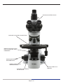
Page 8
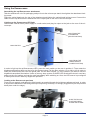
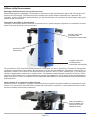
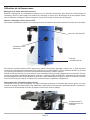
HEAD LOCK SCREW
LED ILLUMINATOR
ILLUMINATOR LOCK
SCREW
FILTER SELECTOR (1)

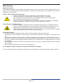
Page 9
JACK FROM THE
POWER SUPPLY
(LOWER POSITION)
JACK FROM THE
ILLUMINATOR
(UPPER POSITION)
MAIN SWITCH
SLIDE THE BLACK
PLATE BETWEEN
STAGE AND CLAMP
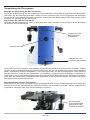
Using the uorescence
Assembling the epi-uorescence attachment
Take the attachment out of its packaging and put it onto the microscope stand, then tighten the attachment lock-
ing screw.
Place the optical head onto the top of the attachment and tighten the optical head locking screw. Connect the
cable from the epi-uorescence attachment to the output jack on the rear of the microscope.
Lighting up the uorescence LED light
Connect the external 6Vdc power supply to a wall socket, and plug its output to the jack on the rear of the mi-
croscope:
In order to light up the epi-uorescence LED, press the main switch on the rear in position II. Then rotate the
brightness adjustment knob on the left to the desired value. Pull the lter selector (1) to right or left in order to
insert the uorescence lter into the optical path. Put the lter selector (1) in the center if you want to use the
brighteld transmitted illumination. Unlike a mercury lamp system, B-383LD LED illumination doesn’t need any
power-up time for heating, and can be used immediately after switching on. Also, the LED source is pre-aligned
in factory and doesn’t need any alignment operation.
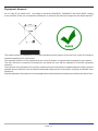
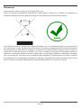
Looking at the uorescent specimen
Focus on your sample, and adjust the light intensity as needed through the brightness adjustment knob. In order
to improve the darkness of the background (thus improving contrast), it is strongly suggested to put the provided
black plate under the stage):

Page 10
Maintenance
Microscopy environment
This microscope is recommended to be used in a clean, dry and shock free environment with a temperature of
0-40°C and a maximum relative humidity of 85 % (non condensing). Use a dehumidier if needed.
To think about when and after using the microscope
• The microscope should always be kept vertically when moving it and be careful so that no
moving parts, such as the eyepieces, fall out.
• Never mishandle or impose unnecessary force on the microscope.
• Never attempt to service the microscope yourself.
• After use, turn off the light immediately, cover the microscope with the included
dust-cover, and keep it in a dry and clean place.
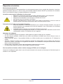
Electrical safety precautions
• Before plugging in the power supply, make sure that the supplying voltage of your region
matches with the operation voltage of the equipment and that the lamp switch is in off-
position.
•
Users should observe all safety regulations of the region. The equipment has acquired
the CE safety label. However, users do have full responsibility to use this equipment safely.
Cleaning the optics
• If the optical parts need to be cleaned try rst to: use compressed air.
• If that is not sufcient: use a soft lint-free piece of cloth with water and a mild detergent.
• And as a nal option: use the piece of cloth moistened with a 3:7 mixture of ethanol and ether.
Note: ethanol and ether are highly ammable liquids. Do not use them near a heat source, near sparks or
near electric equipment. Use these chemicals in a well ventilated room.
• Remember to never wipe the surface of any optical items with your hands. Fingerprints can damage the
optics.
• Do not disassemble objectives or eyepieces in attempt to clean them.
For the best results, use the OPTIKA cleaning kit (see catalogue).
If you need to send the microscope to Optika for maintenance, please use the original packaging.

Page 11
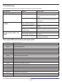
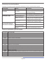
Troubleshooting
Review the information in the table below to troubleshoot operating problems.
PROBLEM CAUSE SOLUTION
LIGHT DOESN’T TURN ON Power supply not connected Check that the 6Vdc power supply jack
is well inserted on the rear of the micro-
scope
Rotate the brightness adjustment control
and check if there is an increase in the
light output
IMAGE CANNOT BE SEEN OR
IS DARK.
The iris diaphragm aperture
is not completely opened
Completely open the iris diaphragm aper-
ture
Brightness level is low Rotate the brightness adjustment potenti-
ometer
Objective is not aligned with
the optical axis
Rotate the nosepiece until an objective is
well inserted in the optical path (it “clicks”)
IMAGE IS UNCLEAR, BLURRED
OR HAS INSUFFICIENT CON-
TRAST.
Objectives or lters are dirty Wipe them clean
The iris diaphragm aperture
is not opened correctly
Open the iris diaphragm aperture
completely
Condenser at wrong height Rotate the condenser knob until you see
a uniform illumination
User replaceable accessories and spare parts
CAT. NO. DESCRIPTION
M-160 Eyepiece WF10x/20mm.
M-161 Eyepiece WF15x.
M-162 Eyepiece WF20x.
M-163 Micrometer eyepiece WF10x/20mm.
M-005 26x76 mm micrometric slide. Range 1 mm, div. 0,01 mm.
M-144 Objective 4x/0,10 E-PLAN IOS.
M-145 Objective 10x/0,25 E-PLAN IOS.
M-146 Objective 20x/0,40 E-PLAN IOS.
M-147 Objective 40x/0,65 E-PLAN IOS
M-149 Objective 60x/0,80 E-PLAN IOS.
M-148 Objective 100x/1,25 E-PLAN IOS (Oil).
M-335 Objective PLAN IOS MET 50x/0.75.
M-173 Photo adapter for APS-C and Full Frame Reex cameras.
M-114 C-Mount adapter for 1/2” sensor.
M-069 Solar battery pack.
M-181 Complete Phase Contrast Set with IOS PLAN obj. 10x, 20x, 40x, 100x , with Darkfifi eld position.
M-174.1 Polarising set, fifi lters only (for B-380 series).
M-175 Rotating table for polarising set.
M-185 Darkfifield condenser for Dry Objectives.
M-116 C-Mount adapter for 2/3” sensor.

Page 12
Equipment disposal
Art.13 Dlsg 25 july 2005 N°151. “According to directives 2002/95/EC, 2002/96/EC and 2003/108/EC relating
to the reduction in the use of hazardous substances in electrical and electronic equipment and waste disposal.”
The basket symbol on equipment or on its box indicates that the product at the end of its useful life should be
collected separately from other waste.
The separate collection of this equipment at the end of its lifetime is organized and managed by the producer.
The user will have to contact the manufacturer and follow the rules that he adopted for end-of-life equipment
collection.
The collection of the equipment for recycling, treatment and environmentally compatible disposal, helps to prevent
possible adverse effects on the environment and health and promotes reuse and/or recycling of materials of the
equipment.
Improper disposal of the product involves the application of administrative penalties as provided by the laws in force.

Modello
B-383LD1
B-383LD2
Serie B-380
MANUALE D’ISTRUZIONI
Versione: 2
Emesso il: 18, 03, 2015

Pagina 14
Indice Contenuti
Avvertenza
Simboli
Informazioni sulla sicurezza
Utilizzo previsto
Contenuto della confezione
Apertura della confezione
Speciche tecniche
Descrizione dello strumento
Istruzioni per l’uso
Utilizzo della uorescenza
Manutenzione
Soluzioni per eventuali problemi
Accessori sostituibili e parti di ricambio
Smaltimento

Pagina 15
Avvertenza
Questo microscopio è uno strumento scientico di alta precisione, progettato per durare a lungo con una mini-
ma manutenzione; la realizzazione è secondo i migliori standard ottici e meccanici, per poter essere utilizzato
quotidianamente. Vi ricordiamo che questo manuale contiene informazioni importanti per la sicurezza e per la
manutenzione dello strumento, e deve quindi essere messo a disposizione di coloro che lo utilizzeranno.
Decliniamo ogni responsabilità derivante da un utilizzo dello strumento non indicato nel presente manuale.
Simboli
La seguente tabella riporta i simboli utilizzati in questo manuale.
PERICOLO
Questo simbolo indica un rischio potenziale ed avverte di procedere con cautela.
SHOCK ELETTRICO
Questo simbolo indica un rischio di shock elettrico.
Informazioni sulla sicurezza
Per evitare shock elettrici
Prima di collegare il cavo di alimentazione alla presa elettrica, assicurarsi che il voltaggio della rete locale coin-
cida con il voltaggio dello strumento e che l’interruttore dell’illuminazione sia nella posizione “Off”.
Gli utenti dovranno seguire tutte le norme di sicurezza locali. Lo strumento è certicato CE. In ogni caso, gli
utilizzatori sono gli unici responsabili per un utilizzo sicuro dello strumento. Per l’utilizzo in sicurezza dello stru-
mento è importante attenersi alle seguenti istruzioni e leggere il manuale in tutte le sue parti.
Utilizzo previsto
Solo per ricerca. Non è previsto alcun utilizzo di questo strumento per uso diagnostico.
Contenuto della confezione
DESCRIZIONE QUANTITÀ
Stativo microscopio con revolver, tavolino, condensatore 1
Testata ottica (trinoculare) 1
Obiettivo E-PLAN IOS 4x 1
Obiettivo E-PLAN IOS 10x 1
Obiettivo E-PLAN IOS 20x 1
Obiettivo E-PLAN IOS 40x 1
Obiettivo PLAN IOS MET 50x 1
Oculare WF10x/20mm 2
Illuminatore per Fluorescenza 1
Copertina antipolvere 1 1
Alimentatore 6Vdc 1

Pagina 16
Apertura della confezione
Il microscopio si trova in un imballaggio di polistirolo espanso stampato. Dopo aver tolto il nastro adesivo da
tutti gli imballi, sollevare la metà superiore dell’imballaggio. Fare attenzione a non far cadere o danneggiare le
componenti ottiche (obiettivi e oculari). Estrarre il microscopio dal suo imballaggio con entrambe le mani (una
intorno al braccio e una intorno alla base) e appoggiarlo su un piano stabile.
Posizionare la testata d’osservazione nella parte superiore del braccio e stringere la vite di serraggio. Inserire
gli oculari nei tubi oculari.
Collegare il cavo per l’alimentazione inserendo il connettore nell’apposita presa posta nella parte posteriore del
microscopio.
Speciche tecniche
B-383LD1
Testata: Ttrinoculare, inclinata 30°, ruotabile 360°. Distanza interpupillare regolabile 48-75mm..
Oculari: WF10X/20mm.
Revolver: revolver inverso 5 posizioni. Ruotante su cuscinetti a sfera..
Obiettivi: E-PLAN IOS 4x/0.10, 10x/0.25, 20x/0.40, 40x/0.65, e PLAN 50x/0.75 (no coprioggetto).
Messa a fuoco: Macro e micrometrica coassiale.
Tavolino: Doppio strato con meccanismo traslatore, dimensioni 216x150mm, range traslazione
78x54mm. Belt-Drive in direzione X..
Condensatore: Condensatore di Abbe, slidin-in, N.A. 1.25 con sistema di centraggio.
Illuminazione: Trasmessa: X-LED
3
, con controllo manuale luminosità.
Epi-Fluorescenza: LED blu ad alta efficienza.
Alimentatore: Alimentatore esterno: Input 100-240Vac 50-60Hz / Output: 6Vdc 1A.
B-383LD2
Testata: Trinoculare, inclinata 30°, ruotabile 360°. Distanza interpupillare regolabile 48-75mm.
Oculari: WF10X/20mm.
Revolver: revolver inverso 5 posizioni. Ruotante su cuscinetti a sfera.
Obiettivi: E-PLAN IOS 4x/0.10, 10x/0.25, 20x/0.40, 40x/0.65, e PLAN 50x/0.75 (no coprioggetto).
Messa a fuoco: Macro e micrometrica coassiale.
Tavolino: Doppio strato con meccanismo traslatore, dimensioni 216x150mm,
range traslazione 78x54mm. Belt-Drive in direzione X.
Condensatore: Condensatore di Abbe, slidin-in, N.A. 1.25 con sistema di centraggio.
Illuminazione: Trasmessa: X-LED
3
, con controllo manuale luminosità.
Epi-Fluorescenza: LED bianco ad alta efficienza (per filtri Blu e Verde).
Alimentatore: Alimentatore esterno: Input 100-240Vac 50-60Hz / Output: 6Vdc 1A.

Pagina 17
USCITA FOTO/VIDEO
VITE SERRAGGIO
TESTA
REVOLVER PORTAOBIETTIVI
TAVOLINO
TRASLATORE
MANOPOLE REGOLAZIONE
SPOSTAMENTO TAVOLO
REGOLAZIONE
LUMINOSITÀ
(LATO SINISTRO)
VITI DI CENTRAGGIO
CONDENSATORE
DIAFRAMMA A IRIDE
OCULARI
CONDENSATORE
ILLUMINATORE A LED
OBIETTIVI
ANELLO DI REGOLAZIONE
DIOTTRICA
Descrizione dello strumento

Pagina 18
PINZA PORTAPREPARATI
COMANDO FUOCO
MICROMETRICO
REGOLAZIONE ALTEZZA
DEL CONDENSATORE
REGOLAZIONE DELLA
TENSIONE
COMANDO FUOCO
MACROMETRICO
LEVA DI BLOCCO
FOCUS
DISTANZA INTERPUPILLARE

Pagina 19
Istruzioni per l’uso
Regolazione della testata di osservazione
Allentare la vite di serraggio, ruotare la testata no a trovare una posizione comoda per l’osservazione e quindi
avvitarla nuovamente.
Posizionamento del vetrino sul tavolo portapreparati
Fissare il vetrino con preparato al piano meccanico mediante l’apposita pinzetta per il sostegno dei campioni.
Regolando le manopole coassiali del piano portaoggetti, assicurarsi che il vetrino si trovi al centro del campo di
osservazione.
Impostazioni del sistema di illuminazione LED – luce trasmessa
Il microscopio è dotato di un illuminatore LED ad alta efcienza. Premere il pulsante di selezione (sul retro del
microscopio) sulla posizione I. Ruotare la manopola di regolazione di intensità no ad ottenere un livello adatto
all’osservazione.
Impostazioni del sistema di illuminazione LED – epilluminazione
Il microscopio è dotato di un illuminatore LED ad alta efcienza. Premere il pulsante di selezione (sul retro del
microscopio) sulla posizione II. Ruotare la manopola di regolazione di intensità no ad ottenere un livello adatto
all’osservazione.
Regolazione della distanza interpupillare
Regolare la distanza interpupillare dei portaoculari sulla testata no ad ottenere la visione di un unico campo
luminoso circolare tenendo ferme le parti destra e sinistra della testata di osservazione con entrambe le mani.
Regolazione della messa a fuoco e compensazione diottrica
Ruotare l’anello di regolazione diottrica sull’oculare sinistro in posizione zero. Ruotare la manopola di messa a
fuoco no a mettere a fuoco il campione con un obiettivo a basso ingrandimento. Aggiustare la micrometrica no
ad ottenere un’immagine chiara e nitida osservando con l’occhio destro, poi agire sull’anello di compensazione
diottrica sull’oculare sinistro osservando con l’occhio sinistro. Ruotare la manopola di regolazione della tensione
della messa a fuoco no ad avere una giusta tensione del sistema di messa fuoco.
Regolazione del condensatore
Alzare o abbassare il condensatore mediante l’apposita manopola per ottenere un’illuminazione chiara e unifor-
me dell’oggetto. Per centrare il condensatore servirsi delle due viti di centraggio.
Impostazione dell’apertura numerica
Per impostare l’apertura numerica dell’illuminatore, regolare l’apertura del diaframma a iride. In questo modo si
controllano contrasto e risoluzione dell’immagine.

Pagina 20
VITE FISSAGGIO TESTA
ILLUMINATORE LED
VITE FISSAGGIO
ILLUMINATORE
SELETTORE FILTRI (1)
La pagina si sta caricando...
La pagina si sta caricando...
La pagina si sta caricando...
La pagina si sta caricando...
La pagina si sta caricando...
La pagina si sta caricando...
La pagina si sta caricando...
La pagina si sta caricando...
La pagina si sta caricando...
La pagina si sta caricando...
La pagina si sta caricando...
La pagina si sta caricando...
La pagina si sta caricando...
La pagina si sta caricando...
La pagina si sta caricando...
La pagina si sta caricando...
La pagina si sta caricando...
La pagina si sta caricando...
La pagina si sta caricando...
La pagina si sta caricando...
La pagina si sta caricando...
La pagina si sta caricando...
La pagina si sta caricando...
La pagina si sta caricando...
La pagina si sta caricando...
La pagina si sta caricando...
La pagina si sta caricando...
La pagina si sta caricando...
La pagina si sta caricando...
La pagina si sta caricando...
La pagina si sta caricando...
La pagina si sta caricando...
La pagina si sta caricando...
La pagina si sta caricando...
La pagina si sta caricando...
La pagina si sta caricando...
La pagina si sta caricando...
La pagina si sta caricando...
La pagina si sta caricando...
La pagina si sta caricando...
La pagina si sta caricando...
La pagina si sta caricando...
La pagina si sta caricando...
La pagina si sta caricando...
-
 1
1
-
 2
2
-
 3
3
-
 4
4
-
 5
5
-
 6
6
-
 7
7
-
 8
8
-
 9
9
-
 10
10
-
 11
11
-
 12
12
-
 13
13
-
 14
14
-
 15
15
-
 16
16
-
 17
17
-
 18
18
-
 19
19
-
 20
20
-
 21
21
-
 22
22
-
 23
23
-
 24
24
-
 25
25
-
 26
26
-
 27
27
-
 28
28
-
 29
29
-
 30
30
-
 31
31
-
 32
32
-
 33
33
-
 34
34
-
 35
35
-
 36
36
-
 37
37
-
 38
38
-
 39
39
-
 40
40
-
 41
41
-
 42
42
-
 43
43
-
 44
44
-
 45
45
-
 46
46
-
 47
47
-
 48
48
-
 49
49
-
 50
50
-
 51
51
-
 52
52
-
 53
53
-
 54
54
-
 55
55
-
 56
56
-
 57
57
-
 58
58
-
 59
59
-
 60
60
-
 61
61
-
 62
62
-
 63
63
-
 64
64


Optika B-383LD1 Manuale utente
- Categoria
- Microscopi
- Tipo
- Manuale utente
- Questo manuale è adatto anche per
in altre lingue
- English: Optika B-383LD1 User manual
- français: Optika B-383LD1 Manuel utilisateur
- español: Optika B-383LD1 Manual de usuario
- Deutsch: Optika B-383LD1 Benutzerhandbuch
Documenti correlati
Altri documenti
-
LG ATNW36GMLS1 Guida d'installazione
-
3B SCIENTIFIC PHYSICS 300 1013368 Manuale utente
-
-
Bresser Biolux Touch 5MP HDMI digital Microscope for School and Hobby Manuale del proprietario
-
-
 Optika Italy B-150P Series Manuale utente
-
Celestron Celestron Labs CB2000C Manuale utente
-
-
-
