L854200003
03/2018 rev 1
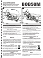
BOB 50M
BOB 50ME
UNIONE NAZIONALE COSTRUTTORI
AUTOMATISMI PER CANCELLI, PORTE
SERRANDE ED AFFINI


3
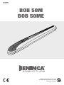
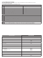
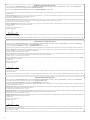
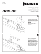
455 / 485 / 520
857
100
121
48
70
146
980
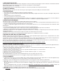
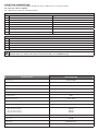
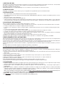
Dimensioni d’ingombro / Overall dimensions / Abmessungen
Dimensions d’encombrement / Dimensiones exteriores / Wymiary gabarytowe

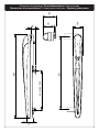
4
1
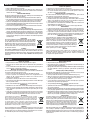
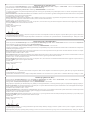
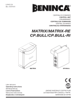
Apertura max
Max Opening
Max. Öffung
Ouverture max
Abiertura max.
X Y
Z
K
M*
max.
Tempo apertura
Opening time
Öffungszeit
Temps d'ouverture
Tiempo de abiertura
Prędkość kątowa
(90°)
Dimensioni max anta
Max wing dimensions
Max Flügelmasse
Dimens. max de la porte
Dimens. max de la hoja
L (m) P (kg)
90 150 150 80 695 90 25”
2,5 450
3 400
3,5 350
4* 300
90 225 225 140 625 155 38”
2,5 600
3 550
3,5 500
4* 400
4,5* 350
5* 300
100 200 200 115 650 130 34”
2,5 600
3 550
3,5 500
4* 400
4,5* 350
5* 300
110 175 175 95 680 110 30”
2,5 450
3 400
3,5 350
4* 300
X
K
P S
Y
M
Z
M
Y
X
110°
max
M = +20mm / K = -10mm
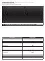
Fig. 1a
Fig. 1b
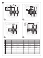
* Consigliabile l’utilizzo di elettroserratura
* It is advisable to use an electric lock
* Wir empfehlen den Einsatz eines Elektroschlosses
* On suggère l’utilisation d’une serrure électrique
* Aconsejado el empleo de la cerradura eléctrica
* Zaleca się zainstalowanie zamka elektrycznego
90°

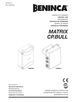
5
3
2
V1
V2
B
B
P
A
F
D
D
P
P
S V
R
C
T
Mettere a livello.
Level.
Nivellieren.
Mettre de niveau.
Nivelar.
Ustawić na wysokości
Saldare.
Weld.
Anschweißen.
Souder.
Soldar.
Spawać
Saldare.
Weld.
Anschweißen.
Souder.
Soldar.
Spawać.
Rondella in plastica + Grasso
Plastic washer +Grease
Kunststoffscheibe + Fett
Rondelle en plastique + Graisse
Arandela de plástico + Grasa
Plastikowe podkładki + Smar
Grasso
Grease
Fett
Graisse
Grasa
Smar

6
4
5
V
P
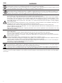
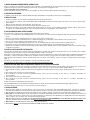
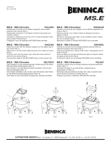
Posizione 2 (PG11)
Position 2 (PG11)
Position 2 (PG11)
Position 2 (PG11)
Posición 2 (PG11)
Pozycja 2 (PG11)
Posizione 1 (PG13,5)
Position 1 (PG13,5)
Position 1 (PG13,5)
Position 1 (PG13,5)
Posición 1 (PG13,5)
Pozycja 1 (PG13,5)
Condensatore 9μF
Capacitor 9μF
Kondensator 9μF
Condensateur 9μF
Condensador 9μF
Kondensator 9μF
Cavo alimentazione
Power supply cable
Stromkabel
Câble d’alimentation
Cable de alimentación
Kabel zasilania
Raccordo per guaina o pressacavo
Connection for sheath and cable gland
Anschluss für Hülse oder Kabelhalter
Raccord pour gaine o serre-câble
Empalme para vaina o prensaestopas
Złącze do osłony lub dławika kablowego
Morsettiera
Terminal board
Klemmleiste
Boîte à joints
Regletero
Listwa zaciskowa

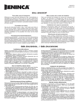
7
6
1 Chiude Close Schließen Ferme Cierra Zamyka
2 Apre Open Öffnen Ouvre Abre Otwiera
3 COM COM COM COM COM COM
4 GND GND GND GND GND GND
5
Segnale ENCODER
Filo Verde
ENCODER signal
Green wire
ENCODER-Signal
Grün Leiter
Signal ENCODEUR
Fil vert
Señal ENCODER
Hilo verde
Sygnał ENKODERA
Zielony przewód
6
Positivo ENCODER
Filo Marrone
ENCODER positive
Brown wire
ENCODER Pluspol
Braun Leiter
Positif ENCODEUR
Fil brun
Positivo ENCODER
Hilo marrón
Dodatni ENKODERA
Brązowy
przewód
7
Negativo ENCODER
Filo Bianco
ENCODER negative
White wire
ENCODER Minuspol
Weiß Leiter
Négatif ENCODER
Fil blanc
Negativo ENCODER
Hilo blanco
Ujemny ENKODERA
Biały przewód
a Filo nero Black wire Schwarzer Leiter Fil noir Hilo negro Czarny przewód
b Filo bianco White wire Weißer Leiter Fil blanc Hilo blanco Biały przewód
c Filo rosso Red wire Roter Leiter Fil rouge Hilo rojo Czerwony przewód
FCC Finecorsa CHIUDE CLOSE limit switch
Endschalter SCHLIESSEN
Fin de course FERME
Final de carrera CIERRA
Ogranicznik ZAMYKA
FCO Finecorsa APRE OPEN limit switch Endschalter ÖFFNEN
Fin de course OUVRE
Final de carrera ABRE
Ogranicznik OTWIERA
M
b
a
c
1 2 3 4
GND
1 2 3 4
a
b
c
5 6 7
GND
M
Encoder
Encoder
Encoder
Codeur
Encoder
Enkoder
M
1
b
a
c
2 3 4
GND
FCO
FCC
b
a
c
FCO
2 3
GND
41
M
a
M
b
a
c
1 2 3 4
GND
1 2 3 4
a
b
c
5 6 7
GND
M
Encoder
Encoder
Encoder
Codeur
Encoder
Enkoder
M
1
b
a
c
2 3 4
GND
FCO
FCC
b
a
c
FCO
2 3
GND
41
M
b
M
b
a
c
1 2 3 4
GND
1 2 3 4
a
b
c
5 6 7
GND
M
Encoder
Encoder
Encoder
Codeur
Encoder
Enkoder
M
1
b
a
c
2 3 4
GND
FCO
FCC
b
a
c
FCO
2 3
GND
41
M
c
M
b
a
c
1 2 3 4
GND
1 2 3 4
a
b
c
5 6 7
GND
M
Encoder
Encoder
Encoder
Codeur
Encoder
Enkoder
M
1
b
a
c
2 3 4
GND
FCO
FCC
b
a
c
FCO
2 3
GND
41
M
d

8
7
A
B
D
E
F
G
B
C
11
2 2
3
4
5

9
ITA
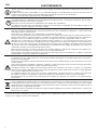
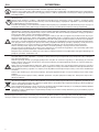
AVVERTENZE
E’ vietato l’utilizzo del prodotto per scopi o con modalità non previste nel presente manuale. Usi non corretti possono essere
causa di danni al prodotto e mettere in pericolo persone e cose.
Si declina ogni responsabilità dall’inosservanza della buona tecnica nella costruzione dei cancelli, nonché dalle deformazioni
che potrebbero verificarsi durante l’uso. Conservare questo manuale per futuri utilizzi.
Questo manuale è destinato esclusivamente a personale qualificato per l’installazione e la manutenzione di aperture auto-
matiche.
L’installazione deve essere effettuaua da personale qualificato (installatore professionale, secondo EN12635), nell’osservanza
della Buona Tecnica e delle norme vigenti.
Verificare che la struttura del cancello sia adatta ad essere automatizzata.
L’installatore deve fornire tutte le informazioni relative al funzionamento automatico, manuale e di emergenza dell’automa-
zione, e consegnare all’utilizzatore dell’impianto le istruzioni d’uso.
I materiali dell’imballaggio non devono essere lasciati alla portata dei bambini in quanto fonte di potenziale pericolo. Non
disperdere nell’ambiente i materiali di imballo, ma separare le varie tipologie (es. cartone, polistirolo) e smaltirle secondo le
normative locali.
Non permettere ai bambini di giocare con i dispositivi di comando del prodotto.
Tenere i telecomandi lontano dai bambini.
Questo prodotto non è destinato a essere utilizzato da persone (bambini inclusi) con capacità fisiche, sensoriali o mentali
ridotte, o con mancanza di conoscenze adeguate, a meno che non siano sotto supervisione o abbiano ricevuto istruzioni
d’uso da persone responsabili della loro sicurezza.
Applicare tutti i dispositivi di sicurezza (fotocellule, coste sensibili, ecc.) necessari a proteggere l’area da pericoli di impatto,
schiacciamento, convogliamento, cesoiamento.
Tenere in considerazione le normative e le direttive in vigore, i criteri della Buona Tecnica, l’utilizzo, l’ambiente di installazione,
la logica di funzionamento del sistema e le forze sviluppate dall’automazione.
L’installazione deve essere fatta utilizzando dispositivi di sicurezza e di comandi conformi alla EN12978 e EN12453.
Raccomandiamo di utilizzare accessori e parti di ricambio originali, utilizzando ricambi non originali il prodotto non sarà più
coperto da garanzia.
Tutte le parti meccaniche ed elettroniche che compongono l'automazione soddisfano i requisiti e le norme in vigore e pre-
sentano marcatura CE.
Prevedere sulla rete di alimentazione un interruttore/sezionatore onnipolare con distanza d’apertura dei contatti uguale o
superiore a 3 mm.
Verificare che a monte dell’impianto elettrico vi sia un interruttore differenziale e una protezione di sovracorrente adeguati.
Alcune tipologie di installazione richiedono il collegamento dell’anta ad un impianto di messa a terra rispondente alle vigenti
norme di sicurezza.
Durante gli interventi di installazione, manutenzione e riparazione, togliere l’alimentazione prima di accedere alle parti elettriche.
Scollegare anche eventuali batterie tampone se presenti. L’installazione elettrica e la logica di funzionamento devono essere
in accordo con le normative vigenti.
I conduttori alimentati con tensioni diverse, devono essere fisicamente separati, oppure devono essere adeguatamente
isolati con isolamento supplementare di almeno 1 mm. I conduttori devono essere vincolati da un fissaggio supplementare
in prossimità dei morsetti. Ricontrollare tutti i collegamenti fatti prima di dare tensione. Gli ingressi N.C. non utilizzati devono
essere ponticellati.
SMALTIMENTO
Come indicato dal simbolo a lato, è vietato gettare questo prodotto nei rifiuti domestici in quanto alcune parti che lo com-
pongono potrebbero risultare nocive per l’ambiente e la salute umana, se smaltite scorrettamente.
L’apparecchiatura, pertanto, dovrà essere consegnata in adeguati centri di raccolta differenziata, oppure riconsegnata al
rivenditore al momento dell’acquisto di una nuova apparecchiatura equivalente.
Lo smaltimento abusivo del prodotto da parte dell’utente comporta l’applicazione delle sanzioni amministrative previste
dalla normativa vigente.
Le descrizioni e le illustrazioni presenti in questo manuale non sono impegnative. Lasciando inalterate le caratteristiche essenziali del
prodotto il fabbricante si riserva il diritto di apportare qualsiasi modifica di carattere tecnico, costruttivo o commerciale senza impegnarsi
ad aggiornare la presente pubblicazione.

10
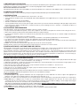
1) DESTINAZIONE D’USO
Questo prodotto è destinato esclusivamente all’apertura e chiusura di porte per passaggio veicolare a battente caratterizzata da limiti
dimensionali e di peso come indicato in questo manuale nel paragrafo “Limiti di impiego”.
Qualsiasi altro utilizzo non è consentito.
Automatismi Benincà non è responsabile per utilizzi non conformi a quelli indicati nelle presenti istruzioni.
2) LIMITI DI IMPIEGO
Nella tabella di fig.1 sono indicati i valori massimi (peso per lunghezza anta) ammissibili per l’automazione BOB.
3) INTRODUZIONE
• Prima di procedere all’installazione leggere le istruzioni qui riportate.
• È fatto divieto assoluto di utilizzare il prodotto BOB 50M / BOB 50ME per applicazioni diverse da quelle contemplate dalle presenti
istruzioni.
• Istruire l’utilizzatore all’uso dell’impianto.
•
Consegnare all’utilizzatore le istruzioni ad esso rivolte.
• Tutti i prodotti Benincà sono coperti da polizza assicurativa che risponde di eventuali danni a cose o persone causati da difetti di
fabbricazione, richiede però la marcatura CE della ”macchina” e l’utilizzo di componenti originali Benincà.
4) VERIFICHE PRELIMINARI
Prima di procedere con l’installazione è indispensabile effettuare alcune verifiche:
• Provare ad aprire manualmente il cancello, le ante si devono muovere senza sforzo e senza punti di resistenza per tutta la loro corsa.
• Lasciata in qualsiasi posizione intermedia l’anta non si deve muovere.
• I cardini e i componenti soggetti ad usura devono essere in perfetta efficienza. In caso contrario provvedere alla sostituzione delle
parti difettose.
• La struttura della porta deve presentare una buona robustezza e rigidità delle ante.
• Con il cancello completamente chiuso, verificare che le ante combacino perfettamente per tutta lo loro altezza.
• I pilastri di sostegno delle ante devono essere idonei al fissaggio dei motoriduttori.
• BOB dispone di arresti meccanici regolabili sia in apertura sia chiusura, è comunque consigliata la presenza di un fermo di arresto in
chiusura a terra (fig.1).
L’affidabilità e la sicurezza dell’automazione dipendono dallo stato della struttura del cancello.
Verificate di avere lo spazio necessario per poter installare l’operatore, in condizioni di sicurezza e comodità.
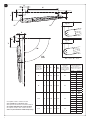
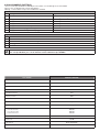
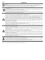
5) MESSA IN POSA DELL’AUTOMATISMO
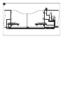
Stabilire l’altezza dal suolo dell’automatismo (si consiglia il più centrato possibile rispetto al portone ed in corrispondenza di un solido
traverso). Saldare quindi la piastra P rispettando le quote di fig. 1.
Con il portone in chiusura, saldare la staffa S rispettando la quota di fig. 1, ad un traverso del portone o ad altro elemento adeguatamente
robusto; tener presente che in questa condizione l’attuatore non deve essere totalmente a fine corsa.
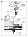
Rimuovere il coperchio di protezione C svitando la vite F, quindi fissare l’attuatore alla piastra P tramite la vite T, ed il dado D (fig. 2).
Bloccare infine l’attuatore alla piastra S tramite la vite V e la rondella R.
Le forature presenti nell’attuatore (fig.1a-1b), agevolano il rispetto delle quote di installazione ottimali.
6) REGOLAZIONE FERMI MECCANICI
L’attuatore è provvisto di fermi meccanici regolabili in apertura e chiusura. La regolazione si effettua posizionando opportunamente i
blocchi meccanici “Open” e “Close”, come indicato di seguito (fig. 3):
1) Sbloccare l’automazione, utilizzando l’apposita leva di sblocco, come indicato nelle istruzioni per l’utilizzatore (pag. 21-22).
2) Portare l’anta nella posizione di chiusura.
3)
Allentare le viti V1 e muovere il blocco “Close” fino a portarlo in battuta sul perno “P”, fissare le viti V1.
4) Portare l’anta nella posizione di apertura.
5)
Allentare le viti V2 e muovere il blocco “Open” fino a portarlo in battuta sul perno “P”, fissare le viti V2.
6) Rispristinare il funzionamento automatico.
Nel modello BOB 50M sono presenti due microinterruttori di finecorsa vincolati ai fermi meccanici.
L’intervento dei microinterruttori avviene con un leggero anticipo rispetto alla battuta meccanica.
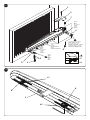
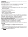
7) COLLEGAMENTI
1) L’apposita piastrina P (fig. 4) consente l’utilizzo di raccordo per guaina o pressacavo PG11 oppure PG13,5. Una volta applicato il tipo
di pressacavo scelto alla piastrina, fissare quest’ultima al carter riduttore tramite le viti V.
2) Inserire il/i cavo/i facendolo/i passare sotto alla morsettiera come in fig.5 per lasciare spazio al condensatore.
3) BOB 50M: effettuare il cablaggio facendo riferimento allo schema riportato in fig.6a (uso di entrambi i finecorsa). Per utilizzare il solo
finecorsa di apertura o solo i fermi meccanici modificare i cablaggi come in figura 6b (solo finecorsa in apertura) o 6c (solo fermi
meccanici).
N.B: nei collegamenti di fig. 6a e 6b il condensatore NON deve assolutamente essere spostato in centrale, mentre nel
collegamento di fig. 6c il condensatore puo’ anche essere spostato in centrale.
4) BOB 5ME: effettuare il cablaggio facendo riferimento allo schema di fig. 6d.
5) E’ obbligatorio effettuare il collegamento di messa a terra utilizzando l’apposito morsetto GND.

11
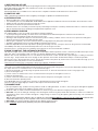
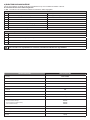
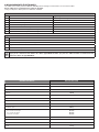
8) COLLEGAMENTI ELETTRICI
I cavi necessari per l’installazione di BOB possono variare a seconda degli accessori installati.
Nessun cavo di collegamento è fornito in dotazione.
Nella fig. 7 sono indicati i cavi per una installazione standard.
Elenco cavi
Collegamento Tipo
A Alimentazione di rete alla centrale di comando 3x1,5mm
2
B Collegamento motore 4x1,5mm
2
(3x0,5mm
2
BOB 50ME)
C Collegamento trasmettitore fotocellula 2x1,0mm
2
D Collegamento ricevitore fotocellula 4x1,0mm
2
E Collegamento selettore a chiave per il comando dall'esterno 2x1,0mm
2
F Collegamento luce lampeggiante di segnalazione 2x1,5mm
2
G Collegamento antenna integrata nel lampeggiante RG 58
Legenda
1 Motoriduttore
2 Fotocellula
3 Selettore a chiave (da esterno) o tastiera digitale
4 Lampeggiante
5 Centrale elettronica
I cavi utilizzati devono essere adatti al tipo di collegamento. Ad esempio per i collegamenti protetti da canalina utiliz-
zare cavi tipo H03VV-F, per i cavi in ambiente esterno utilizzare il tipo H07RN-F.
DATI TECNICI BOB50M / BOB50ME
Alimentazione 230Vac 50/60Hz
Potenza assorbita 310 W
Assorbimento 1,4 A
Spinta 3500 N
Intermittenza di lavoro 30%
Grado di protezione IP44
Temp. funzionamento -20°C / +50°C
Condensatore 9 μF
Peso max. anta 600 kg
Corsa utile:
- con 2 fermi meccanici
- con 1 fermo meccanico
- senza fermi meccanici
455 mm
485 mm
520 mm
Velocità traslazione 0,7 m/min
Rumorosità <70 dB
Lubrificazione Grasso Permanente
Peso 11,6 kg

12
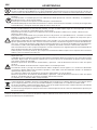
ENG
WARNING
The product shall not be used for purposes or in ways other than those for which the product is intended for and as described
in this manual. Incorrect uses can damage the product and cause injuries and damages.
The company shall not be deemed responsible for the non-compliance with a good manufacture technique of gates as well
as for any deformation, which might occur during use. Keep this manual for further use.
This manual has been especially written to be use by qualified fitters. Installation must be carried out by qualified personnel
(professional installer, according to EN 12635), in compliance with Good Practice and current code. Make sure that the struc-
ture of the gate is suitable for automation. The installer must supply all information on the automatic, manual and emergency
operation of the automatic system and supply the end user with instructions for use.
Packaging must be kept out of reach of children, as it can be hazardous. For disposal, packaging must be divided the various
types of waste (e.g. carton board, polystyrene) in compliance with regulations in force.
Do not allow children to play with the fixed control devices of the product. Keep the remote controls out of reach of children.
This product is not to be used by persons (including children) with reduced physical, sensory or mental capacity, or who
are unfamiliar with such equipment, unless under the supervision of or following training by persons responsible for their
safety. Apply all safety devices (photocells, safety edges, etc.) required to keep the area free of impact, crushing, dragging
and shearing hazard.
Bear in mind the standards and directives in force, Good Practice criteria, intended use, the installation environment, the
operating logic of the system and forces generated by the automated system.
Installation must be carried out using safety devices and controls that meet standards EN 12978 and EN 12453.
Only use original accessories and spare parts, use of non-original spare parts will cause the warranty planned to cover the
products to become null and void.
All the mechanical and electrical parts composing automation must meet the requirements of the standards in force and
outlined by CE marking.
An omnipolar switch/section switch with remote contact opening equal to, or higher than 3mm must be provided on the
power supply mains.
Make sure that before wiring an adequate differential switch and an overcurrent protection is provided.
Pursuant to safety regulations in force, some types of installation require that the gate connection be earthed.
During installation, maintenance and repair, cut off power supply before accessing to live parts. Also disconnect buffer bat-
teries, if any are connected.
The electrical installation and the operating logic must comply with the regulations in force.
The leads fed with different voltages must be physically separate, or they must be suitably insulated with additional insulation
of at least 1 mm. The leads must be secured with an additional fixture near the terminals.
During installation, maintenance and repair, interrupt the power supply before opening the lid to access the electrical parts
Check all the connections again before switching on the power.
The unused N.C. inputs must be bridged.
WASTE DISPOSAL
As indicated by the symbol shown, it is forbidden to dispose this product as normal urban waste as some parts might be
harmful for environment and human health, if they are disposed of incorrectly.
Therefore, the device should be disposed in special collection platforms or given back to the reseller if a new and similar device
is purchased. An incorrect disposal of the device will result in fines applied to the user, as provided for by regulations in force.
Descriptions and figures in this manual are not binding. While leaving the essential characteristics of the product unchanged, the ma-
nufacturer reserves the right to modify the same under the technical, design or commercial point of view without necessarily update
this manual.

13
1) DESTINATION OF USE
This product is destined exclusively for the opening and closure of swing doors for the passage of vehicles, characterised by dimensional
limits and weight as indicated in this manual in the “Limits of use” paragraph.
No other use is allowed.
Automatismi Benincà is not liable for uses that are not in compliance with those indicated in these instructions.
2) LIMITS OF USE
Table 1 indicates the maximum values (weight by leaf length) acceptable for the BOB automation
3) INTRODUCTION
• Before installing the system, read the instruction herein.
• It is mandatory not to use the BOB 50M / BOB 50ME item for applications different from those indicated in the instructions herein.
• Supply the end user with instructions for using this system.
•
The end user should receive special instruction manual.
• All Benincà items are covered by an insurance policy for damages and injuries caused by manufacture faults. It is however required
that the machine bear the CE marking and original Benincà parts be used.
4) PRELIMINARY CHECKS
It is indispensable to carry out several checks before starting installation:
• Try and open the gate manually, the leaves must move without effort and without points of resistance for the entire run.
• When left in any intermediate position the leaf must not move.
• The hinges and components subject to wear must be in perfect working condition. If this is not the case, replace the faulty parts.
• The door structure must be strong and the leaves rigid.
• With the gate completely closed, check that the leaves are aligned perfectly along their entire length.
• The pillars supporting the leaves must be suitable for fixing the gear motors.
• BOB has adjustable mechanical stops both in opening and closing. However, a stop for closure on the ground is recommended.
The reliability and safety of the automation depend on the state of the gate structure.
Check that there is enough space for installation of the operator in safe and comfortable conditions.
5) HOW TO INSTALL THE AUTOMATIC SYSTEM
Calculate the height of the system from the ground (it is advisable to define a position as much centred as possible with respect to the
main door and in correspondence with a strong cross girder). Weld the plate P, following measures in Fig. 1.
With the door closed, weld bracket S to a cross beam of the main door or other element with equal strength, according to measures
shown in Fig. 1. Keep in mind that, when carrying out this operation, the actuator should not be totally in a stroke end position.
Remove the cover C by loosening the screw F. Then fix the actuator to the plate P by means of the screw T and the nut D (Fig. 2). Lock
the actuator to plate S by means of screw V and washer R.
The holes in the acturator (Fig. 1a-1b) help to keep to the optimum installation measures.
6) HOW TO ADJUST THE MECHANICAL STOPPERS
The actuator is provided with adjustable mechanical stoppers in the opening and closing phases. The system is adjusted by suitably positioning
the “Open” and “Close” mechanical locks, as shown hereunder (Fig.3):
1) Unlock the automatic system by using the special release lever, as shown in the instructions for the user (page 21-22).
2) Close the door/gate leaf.
3) Loosen screws V1 and move the “Close” lock until it reaches the pivot P, then tighten screws V1.
4) Open the door/gate leaf.
5) Loosen screws V2 and move the “Open” lock until it reaches the pivot P, then tighten screws V2.
6) Reset the automatic operating mode.
In the BOB 50M version, two limit micro-switches are provided fixed to the mechanical stoppers.
The micro-switches trigger slightly in advance with respect to the mechanical stop.
7) CONNECTIONS
1) The special plate P (Fig. 4) allows for using a link for sheath or cable gland PG11, or PG13,5. Once the type of cable gland is applied
to the plate, fix the latter to the adaptor cover by means of screws V.
2) Insert the cable, or cables, under the terminal board, as shown in Fig.5. This will leave enough space for the capacitor.
3) BOB 50M: carry out the wiring by referring to the wire diagram shown in Fig 6a (use both limit switches). In order to use either the
opening limit switch or the mechanical stoppers, change wiring as shown in Fig. 6b (opening limit switch only) or 6c (mechanical
stoppers only).
N.B: in wiring connections shown in Fig. 6a and 6b, the capacitor MUST NOT be connected to the control unit, while for wire
connection shown in Fig. 6c, the capacitor can be connected to the control unit.
4) BOB 50ME: carry out the wiring by referring to wire diagram shown in Fig 6d.
5) It is mandatory to provide for ground by using the special GND terminal.

14
TECHNICAL DATA BOB50M/BOB50ME
Power supply 230Vac 50/60Hz
Absorbed rating 310 W
Absorbed current 1,4 A
Thrust 3500 N
Jogging 30%
Protection degree IP44
Operating temperature -20°C / +50°C
Capacitor 9 μF
Door leaf max. weight 600 kg
Useful stroke:
- with 2 mechanical stoppers
- with 1 mechanical stopper
- without mechanical stoppers
455 mm
485 mm
520 mm
Traversing speed 0,7 m/min
Noise level <70 dB
Lubrification Permanent grease
Weight 11,6 kg
8) ELECTRIC CONNECTIONS
The cables necessary for the installation of BOB can vary according to the accessories installed.
No connection cable is supplied.
Fig. 7 indicates the cables for standard installation.
List of cables
Connection Type
A Mains power supply to the control unit 3x1,5mm
2
B Motor connection 4x1,5mm
2
(3x0,5mm
2
BOB 50ME)
C Photocell transmitter connection 2x1,0mm
2
D Photocell receiver connection 4x1,0mm
2
E Key selector connection for external command 2x1,0mm
2
F Flashing signal light connection 2x1,5mm
2
G Connection of the aerial built-in the flashing light RG 58
Legenda
1 Motoreducer
2 Photo-electric cells
3 Key selector (external) or digital keyboard
4 Flash-light
5 Electronic board
The cables used must be suitable for the type of connection. For example, for connection protected by raceways use
H03VV-F cables, for cables in the outdoor environment always use the H07RN-F type.

15
DEU
HINWEISE
Das Produkt darf nicht für andere Zwecke oder auf andere Weise verwendet werden, als in der vorliegenden Anleitung be-
schrieben.
Ein ungeeigneter Gebrauch kann das Produkt beschädigen und eine Gefahr für Personen und Sachen darstellen.
Wir übernehmen keinerlei Haftung für Schäden, die sich aus einer unsachgerechten Montage der Tore und aus daraus fol-
genden Verformungen ergeben können. Bewahren Sie dieses Handbuch für Nachschlagzwecke auf.
Dieses Handbuch ist ausschließlich qualifiziertem Personal für die Installation und Wartung von automatischen Öffnungsvor-
richtungen bestimmt.
Die Installation muss vonFachpersonal(professioneller Installateur gemäß EN12635) unter Beachtung der Regeln der guten
Technik sowie der geltenden Normen vorgenommen werden.
Prüfen, dass die Struktur des Tors so ist, dass es automatisiert werden kann.
Der Installateur hat dem Benutzer alle Informationen über den automatischen, manuellen Betrieb sowie den Not-Betrieb der
Automatik zusammen mit der Bedienungsanleitung zu liefern.
Das Verpackungsmaterial fern von Kindern halten, da es eine potentielle Gefahr darstellt. Das Verpackungsmaterial nicht ins
Freie werfen, sondern je nach Sorte (z.B. Pappe, Polystyrol) und laut den örtlich geltenden Vorschriften entsorgen. Erlauben
Sie es Kindern nicht, mit den Steuervorrichtungen dieses Produkts zu spielen.
Halten Sie die Fernbedienungen von Kindern fern. Dieses Produkt eignet sich nicht für den Gebrauch durch Personen
(einschließlich Kindern) mit eingeschränkten körperlichen, sensorischen oder geistigen Fähigkeiten oder ohne die nötigen
Kenntnisse, es sei denn, sie werden von für ihre Sicherheit verantwortlichen Personen beaufsichtigt oder angeleitet.
Wenden Sie alle Sicherheitsvorrichtungen (Fotozellen, Sensoren usw.) an, die zum Schutz desGefahrenbereiches gegen
Aufprall, Quetschung, Erfassung und Abtrennung von Gliedmaßen erforderlich sind. Berücksichtigen Sie die geltenden Nor-
men und Richtlinien, die Regeln der guten Technik, die Einsatzweise, die Installationsumgebung, die Betriebsweise sowie
die vom System entwickelten Kräfte.
Die Installation muss unter Verwedung von Sicherheits- und Steuerungsvorrichtungen vorgenommen werden, die der Norm
EN 12978 und EN 12453 entsprechen.
Verwenden Sie ausschließlich Originalzubehör und Originalersatzteile, die Verwendung von nicht originalen Teilen zieht einen
Verfall der vom Garantiezertifikat vorgesehenen Gewährleistungen nach sich.
Alle mechanischen und elektrischen Teile der Automatisierung müssen den Vorgaben der gültigen Normen entsprechen und
mit der CE-Kennzeichnung versehen sein.
Das Stromnetz muss mit einem allpoligen Schalter bzw. Trennschalter ausgestattet sein, dessen Kontakte einen Öffnungsab-
stand gleich oder größer als 3 aufweisen.
Kontrollieren, ob der elektrischen Anlage ein geeigneter Differentialschalter und ein Überspannungsschutzschalter vorge-
schaltet sind. Einige Installationstypologien verlangen den Anschluss des Flügels an eine Erdungsanlage laut den geltenden
Sicherheitsnormen.
Während der Installation, der Wartung und der Reparatur, die Anlage stromlos machen bevor an den elektrischen Teilen
gearbeitet wird. Klemmen Sie falls vorhanden auch die eventuellen Pufferbatterien ab.
Die elektrische Installation und die Betriebslogik müssen den geltenden Vorschriften entsprechen. Die Leiter die mit unter-
schiedlichen Spannungen gespeist werden, müssen physisch getrennt oder sachgerecht mit einer zusätzlichen Isolierung
von mindestens 1 mm isoliert werden.
Die Leiter müssen in der Nähe der Klemmen zusätzlich befestigt werden. Während der Installation, der Wartung und der
Reparatur, die Anlage stromlos machen bevor an den elektrischen Teilen gearbeitet wird. Alle Anschlüsse nochmals prüfen,
bevor die Zentrale mit Strom versorgt wird.
Die nicht verwendeten N.C. Eingänge müssen überbrückt werden.
ENTSORGUNG
Das seitlich abgebildete Symbol weißt darauf hin, dass das Produkt nicht als Hausmüll entsorgt werden darf, da einige Be-
standteile für die Umwelt und die menschliche Gesundheit gefährlich sind.
Das Gerät muss daher zu einer zugelassenen Entsorgungsstelle gebracht oder einem Händler beim Kauf eines neuen Geräts
zurückerstattet werden. Eine nicht ordnungsgemäße Entsorgung ist laut Gesetz strafbar.
Die in diesem Handbuch enthaltenen Beschreibungen und Abbildungen sind nicht verbindlich. Ausgenommen der Haupteigenschaften
des Produkts, behält sich der Hersteller das Recht vor eventuelle technische, konstruktive oder kommerzielle Änderungen vorzunehmen
ohne dass er vorliegende Veröffentlichung auf den letzten Stand bringen muss.

16
1) BESTIMMUNGSGEMÄSSER GEBRAUCH
Dieses Produkt ist ausschließlich zum Öffnen und Schließen von Drehflügeltoren für Pkw-Zufahrten bestimmt, deren maximal zulässige
Größen und Gewichte in dieser Anleitung im Abschnitt „Einsatzgrenzen“ angegeben sind.
Jeder andere Einsatz ist unzulässig.
Automatismi Benincà haftet nicht bei von den Angaben in dieser Anleitung abweichender Verwendung.
2) EINSATZGRENZEN
In Tabelle 1 sind die für den Torantrieb BOB zulässigen Maximalwerte angegeben (Gewicht pro Torflügellänge)
3) EINLEITUNG
• Vor der Installation, lesen Sie bitte nachfolgende Anweisungen aufmerksam.
• Es ist strengstens verboten das Produkt BOB 50M / BOB 50ME für andere Anwendungen einzusetzen, als in diesen Anweisungen
beschrieben.
• Weisen Sie den Benutzer in den Gebrauch der Anlage ein.
• Überreichen Sie dem Benutzer die Anweisungen, die ihm bestimmt sind.
• Alle Benincà Produkte sind gegen Schäden oder Unfälle versichert, die sich aus Produktionsmängeln ergeben sollten; dazu müssen
sie jedoch die CE-Markierung tragen und ausschließlich mit Benincà Originalteilen ausgestattet sein.
4) VORAUSGEHENDE PRÜFUNGEN
Vor Beginn der Installation sind unbedingt einige Prüfungen vorzunehmen:
• Das Tor von Hand öffnen, die Drehflügel müssen sich mühelos und ohne Widerstandspunkte über ihren gesamten Weg bewegen
lassen.
• Wird er in einer Zwischenposition gelassen, darf sich der Flügel nicht bewegen.
• Die Torangeln und Verschleißteile müssen voll funktionsfähig sein. Andernfalls sind die defekten Teile auszutauschen.
• Das Tor muss robust gebaut und die Flügel müssen steif sein.
• Kontrollieren Sie bei vollständig geschlossenem Tor, ob die Flügel über ihre ganze Höhe perfekt zusammenpassen.
• Die Pfeiler, an denen die Flügel aufgehängt sind, müssen für die Befestigung der Getriebemotoren geeignet sein.
• BOB besitzt einstellbare mechanische Anschläge für das Öffnen und Schließen, dennoch wird empfohlen, einen festen Schließanschlag
am Boden vorzusehen.
5) INSTALLATION DER AUTOMATIK
Die Höhe der Automatik vom Boden festlegen (zu empfehlen ist ein Maß, das möglichst in der Mitte des Tors auf der Höhe eines soliden
Querträgers liegt). Die Platte P verlöten und dabei die Maße in Abb. 1 beachten.
Wenn das Tor auf Schließen geschaltet ist, den Bügel S an einen Querträger des Tors oder an ein anderes robustes Element entsprechend
der Maße 1, verlöten. Beachten Sie bitte, dass der Aktor in dieser Position nicht ganz bis zum Endanschlag gefahren werden darf.
Die Schraube F abschrauben und den Deckel abnehmen. Den Aktor an die Platte P mit der Schraube T und der Mutter D befestigen
(Abb. 2).
Den Aktor an die Platte S mit der Schraube V und der Scheibe R befestigen.
Die Bohrungen am Aktor (Abb. 1a-1b) dienen der optimalen Befestigungsweise.
6) EINSTELLEN DER MECHANISCHEN FESTSTELLVORRICHTUNGEN
Der Aktor ist mit mechanischen Anschlägen für das Öffnen und Schließen ausgestattet. Die Einstellung erfolgt durch das sachgerechte
Positionieren der mechanischen Feststellvorrichtungen „Open“ und „Close“ wie nachstehend beschrieben (Abb. 3):
1) Die Automatik mit dem entsprechenden Entsicherungshebel und laut Gebrauchsanweisungen des Benutzers entsichern (Seite 21-
22).
2) Den Flügel in die geschlossene Position bringen.
3) Die Schrauben V1 lockern und die Feststellvorrichtung „Close“ bis zum Anschlag an den Stift „P“ verstellen; Schrauben V1
festschrauben.
4) Den Flügel in die offene Position bringen.
5) Die Schrauben V2 lockern und die Feststellvorrichtung „Open“ bis zum Anschlag an den Stift „P“ verstellen; Schrauben V2
festschrauben.
6) Den automatischen Betrieb wieder herstellen.
Das Modell BOB 50M ist mit zwei Mikroendschaltern versehen, die mit den mechanischen Feststellvorrichtungen verbunden sind.
Die Mikroschalter schalten kurz vor dem mechanischen Anschlag ein.
7) ANSCHLÜSSE
1) Das Plättchen P (Abb. 4) ist für den Einsatz eines Anschlusses für eine Hülse oder einen Kabelhalter PG11 oder PG13,5 geeignet.
Nachdem der Kabelhalter am Plättchen befestigt worden ist, letzteres am Kasten des Reduzierers mithilfe der Schrauben V befestigen.
2) Das/die Kabel unterhalb der Klemmleiste durchführen (wie in Abb. 5 gezeigt), um Platz für den Kondensator übrig zu lassen.
3) BOB 50M: Die Verkabelung laut Zeichnung in Abb. 6a vornehmen (beide Endschalter verwenden). Um einen einzigen Endschalter für
das Öffnen oder nur die mechanischen Feststellvorrichtungen zu verwenden, die Verkabelung nach Abb. 6b (nur Endschalter für das
Öffnen) oder 6c (nur mechanische Feststellvorrichtungen) ändern.
N.B.: Bei den Anschlüssen in Abb. 6a und 6b darf der Kondensator AUF KEINEN FALL in die Zentrale eingebaut werden. Das
kann nur erfolgen, wenn der Anschluss laut Abb. 6c vorgenommen wird.
4) BOB 50ME: Die Verkabelung laut Zeichnung in Abb. 6d vornehmen.
5) Der Erdleiter muss an die entsprechende Klemme GND geschlossen werden.

17
TECHNISCHE DATEN BOB50M/BOB50ME
Speisung 230Vac 50/60Hz
Leistung 310 W
Strom-Verbrauch 1,4 A
Druck 3500 N
Betriebsintervall 30%
Shutzgrad IP44
Laufzeit -20°C / +50°C
Kondensator 9 μF
Max. Türflügelgewicht 600 kg
Nützlicher Hub:
- mit 2 Feststellvorrichtungen
- mit 1 mechanischen Feststellvorrichtung
- ohne Feststellvorrichtung
455 mm
485 mm
520 mm
Geschwindigkeit 0,7 m/min
Geräuschpegel <70 dB
Schmierung Permanentfett
Gewicht 11,6 kg
8) ELEKTRISCHE ANSCHLÜSSE
Die für die Installation von BOB erforderlichen Kabel können je nach installiertem Zubehör variieren.
Es werden keine Anschlusskabel mitgeliefert.
In Abb. 7 sind die für eine Standard-Installation erforderlichen Kabel angegeben.
Liste der Kabel
Anschluss Typ
A Netzstromversorgung der Steuerung 3x1,5mm
2
B Anschluss des Motors 4x1,5mm
2
(3x0,5mm
2
BOB 50ME)
C Anschluss Lichtschranken-Sender 2x1,0mm
2
D Anschluss Lichtschranken-Empfänger 4x1,0mm
2
E Anschluss Schlüsselschalter zur Betätigung von außen 2x1,0mm
2
F Anschluss Warn-Blinklicht 2x1,5mm
2
G Anschluss für im Blinklicht integrierte Antenne RG 58
Zeichenerklärung:
1 Getriebemotor
2 Fotozelle
3 Schlüssel-Selektor (außenliegend) oder Digital-Tastatur
4 Blinker
5 Elektroschrank
Die verwendeten Kabel müssen für die Anschlussart geeignet sein. Für die durch Kabelkanal geschützten Anschlüsse
sind z. B. Kabel vom Typ H03VV-F zu verwenden, für Kabel im Außenbereich Typ H07RN-F.

18
FRA
AVERTISSEMENTS
Il est interdit d’utiliser ce produit pour l’utilisation du produit ou avec des finalités ou modalités non prévues par le présent
manuel. Toute autre utilisation pourrait compromettre l’intégrité du produit et présenter un danger pour les personnes ou
pour les biens.
Le fabricant décline toute responsabilité en cas d’utilisation impropre ou d’inobservation de la bonne technique dans la
construction des portails, ainsi que de toute déformation qui pourrait avoir lieu lors de son utilisation.
Toujours conserver la notice pour toute autre consultation future.
Ce manuel est destiné exclusivement au personnel qualifié pour l’installation et la maintenance des ouvertures automatiques.
Le montage doit être accompli par du personnel qualifié (monteur professionnel, conformément à EN12635), dans le respect
del la bonne technique et des normes en vigueur.
Vérifier que la structure du portail est adaptée pour être équipée d’un automatisme.
L’installateur doit fournir toutes les informations relatives au fonctionnement automatique, au déverrouillage d’urgence de
l’automatisme, et livrer à l’utilisateur les modes d’emploi.
Tenir à l’écart des enfants tous les matériaux d’emballage car ils représentent une source potentielle de danger. Ne pas di-
sperser les matériaux d’emballage dans l’environnement, mais trier selon les différentes typologies (i.e. carton, polystyrène)
et les traiter selon les normes locales.
Ne pas laisser les enfants jouer avec les dispositifs de commande du produit.
Conserver les télécommandes hors de la portée des enfants. Ce produit n’est pas prévu pour être utilisé par des personnes
(dont les enfants) dont les capacités physiques, sensorielles ou mentales sont limitées, ou ne disposant pas des connaissances
adéquates, sauf sous surveillance ou après avoir reçu les consignes des personnes responsables de leur sécurité.
Appliquer tous les dispositifs de sécurité (photocellules, linteaux sensibles, etc..) nécessaires pour protéger la zone contre
les risques de choc, d’écrasement, d’entraînement ou de cisaillement. Tenir compte des réglements et des directives en
vigueur, des critéres de bonne technique, de l’utilisation, de l’environnement de l’installation, de la logique de functionnement
du système et des forces développées par l’automatisation.L’installation doit être équipée de dispositifs de sécurité et de
commandes conformes aux normes EN 12978 et EN 12453.
Utiliser exclusivement des accessoires et des pièces de rechange originales, l’utilisation de composants non originaux com-
porte l’exclusion du produit des couvertures prévues par le certificat de Garantie.
Toutes la parties, mécaniques et électriques, qui composent l'automation doivent correspondre aux conditions requises des
réglementations en vigueur et reporter le marquage CE.
Prévoir sur le réseau de l’alimentation un interrupteur / sectionneur omnipolaire avec distance d’ouverture des contacts égale
ou supérieure à 3 mm.. Vérifier la présence en amont de l’installation électrique d’un interrupteur différentiel et d’une protec-
tion de surcourant adéquats.
Certains types d’installation requièrent le branchement du vantail à une installation de mise à terre satisfaisant les normes de
sécurité e vigueur.
Avant toute intervention, d’installation, réparation et maintien, couper l’alimentation avant d’accéder aux parties électriques.
Déconnecter également les batteries tempon éventuellement présentes.
L’installation électrique et la logique de fonctionnement doivent être conformes aux normes en vigueur. Les conducteurs
alimentés à des tensions différentes doivent être séparés physiquement ou bien, ils doivent être isolés en manière appropriée
avec une gaine supplémentaire d’au moins 1 mm.
Les conducteurs doivent être assurés par une fixation supplémentaire à proximité des bornes. Pendant toute intervention
d’installation, maintenance et réparation, couper l’alimentation avant de procéder à toucher les parties électriques.
Recontrôler toutes les connexions faites avant d’alimenter la logique de commande. Les entrées N.F. non utilisées doivent
être shuntées
DÉMOLITION
Comme indiqué par le symbole à coté, il est interdit de jeter ce produit dans les ordures ménagères car les parties qui le
composent pourraient nuire à l’environnent et à la santé des hommes, si traitées et évacuées de manière incorrecte. L’appa-
reillage devra, par conséquent, être livré dans les spéciaux point de collecte et de triage, ou bien remis au revendeur lorsqu’on
décide d’acheter un appareillage équivalent.
L’évacuation abusive du produit de la part de l’usager comporte l’application de sanctions administratives comme prévu
par les normes en vigueur.
Les descriptions et les illustrations présentées dans ce manuel ne sont pas contraignantes. En laissant inaltérées les caractéristiques
essentielles du produit, le fabricant se réserve le droit d’apporter toute modification à caractère technique, de construction ou com-
merciale sans s’engager à revoir la cette publication.

19
1) ESTINATION D’UTILISATION
Ce produit est destiné exclusivement à l’ouverture et à la fermeture des battants pour le passage des véhicules caractérisés par des limites
de dimensions et de poids comme indiqué dans ce manuel au paragraphe «Limites d’Utilisation».
Aucune autre utilisation n’est autorisée.
Automatismi Benincà décline toute responsabilité concernant les utilisations non conformes à celles indiquées dans ce manuel d’instructions.
2) LIMITES D’UTILISATION
Le tableau 1 indique les valeurs maximales (poids pour longueur battant) admissibles pour l’automatisation BOB
3) INTRODUCTION
• Avant de commencer toute installation lire les instructions ci de suite.
• Il est strictement interdit d’utiliser le produit BOB 50M / BOB 50ME pour toute application qui ne soit pas décrite dans ce mode
d’emploi.
• Former l’utilisateur à l’usage de l’installation.
• Remettre à l’utilisateur les instructions d’usage.
• Tous les produits Benincà sont couverts par une police d’assurance qui couvre d’éventuels dommages subis par objets ou personnes
provoqués par des défauts de fabrication. Pourtant il faut qu’il y ait le marquage CE de la « machine » et l’utilisation de pièces et
parties originales Benincà.
4) CONTRÔLES PRÉLIMINAIRES
Il faut absolument, avant de procéder à l’installation, effectuer certains contrôles:
• Essayer d’ouvrir manuellement le portail, celui-ci doit se déplacer sans effort et sans points de résistance tout le long de la course.
• Même dans n’importe quelle position intermédiaire le battant ne doit pas bouger.
• Les gonds et les éléments sujets à l’usure doivent être en parfait état de fonctionnement. Dans le cas contraire, remplacer les éléments
défectueux.
• La structure du battant doit être assez robuste et rigide.
• Lorsque le portail est complètement fermé, contrôler que les battants correspondent parfaitement sur toute la hauteur.
• Les colonnes de soutien des battants doivent être appropriées pour la fixation des motoréducteurs.
• BOB dispose d’arrêtoirs mécaniques réglable aussi bien en ouverture qu’en fermeture, nous conseillons tout de même d’installer un
dispositif de blocage en fermeture à terre.
La fiabilité et la sécurité de l’automatisation dépendent de l’état de la structure du portail.
Contrôler d’avoir l’espace nécessaire pour pouvoir installer l’opérateur, facilement et en toute sécurité.
5) INSTALLATION DE L’AUTOMATISME DE PORTAIL
Décider quelle sera la hauteur du sol désirée pour l’automatisme (on suggère de le centrer le plus possible par rapport au portail et en
correspondance d’une barre solide). Par la suite souder la plaque P en respectant les côtes de la fig. 1.
Avec le portail en fermeture, souder la bride S tout en respectant les côtes de la fig. 1, à une barre du portail ou à n’importe quel autre
élément assez fort. Il faut toujours tenir compte que dans cette condition l’actuateur ne doit pas être complètement en fin de course.
Ôter le couvercle de protection C en dévissant la vis F, par la suite fixer l’actuateur à la plaque P à l’aide de la vis T, et l’écrou D (fig. 2).
En fin bloquer l’actuateur sur la plaque S à l’aide de la vis V et de la rondelle R.
Les trous présents dans l’actuateur (fig.1a-1b), facilitent à respecter les côtes optimales d’installation.
6) RÉGLAGE DES BUTÉES MÉCANIQUES
L’actuateur est équipé de butées mécaniques réglables en ouverture et en fermeture. Le réglage se fait en plaçant dûment les blocages
mécaniques “Open” et “Close”, selon les indications ci de suite (fig. 3):
1) Débloquer l’automation, à l’aide du la spécial levier de déblocage, comme indiqué dans les instruction pour l’usager (pages 21-22).
2) Porter le vantail dans la position de fermeture.
3) Desserrer les vis V1 et ôter le blocage “Close” jusqu’à l’amener en butée sur le tourillon “P”, fixer les vis V1.
4) Porter le vantail dans la position d’ouverture.
5) Desserrer les vis V2 et déplacer le blocage “Open” jusqu’à a l’amener en buté sur le tourillon P”, fixer les vis V2.
6) Rétablir le fonctionnement automatique.
Le modèle BOB 50M comprend deux micro interrupteurs de fin de course liés aux butées mécaniques.
Les micro interrupteurs interviennent légèrement à l’avance vis à vis de la butée mécanique.
7) BRANCHEMENTS
1) La spéciale platine P (fig. 4) permet l’utilisation d’un raccord pour gaine ou serre-câble PG11 ou PG13,5. Après avoir appliqué à la
platine le serre-câble, fixer la platine même au carter réducteur à l’aide des vis V.
2) Insérer le / les câbles en le / les faisant passer sous la boîte à joints comme indiqué dans la fig.5 pour laisser la place au condensateur.
3) BOB 50M: pour le câblage il faut se référer au schéma illustré dans la fig.6a (utilisation des deux fins de course). Pour utiliser
seulement le fin de course d’ouverture ou seulement les butées mécaniques il faut modifier le câblage comme indiqué dans la figure
6b (seulement fin de course en ouverture) ou 6c (seulement butées mécaniques).
N.B: dans les branchement des figures 6a et 6b le condensateur NE DOIT ABSOLUMENT PAS être déplacé dans la centrale,
tandis que pour le branchement illustré dans la fig. 6c le condensateur peut aussi être déplacé dans la centrale.
4) BOB 50ME: effectuer le câblage en se référant au schéma de la fig. 6d.
5) Il est obligatoire effectuer le branchement de mise à terre en utilisant la spéciale borne GND.

20
DONNEES TECHNIQUE
BOB50M/BOB50ME
Alimentation 230Vac 50/60Hz
Puissance absorbé 310 W
Courant absorbé 1,4 A
Poussée 3500 N
Intermittence travail 30%
Degré de protection IP44
Température de fonct. -20°C / +50°C
Condensateur 9 μF
Poids max. porte 600 kg
Course utile:
- avec 2 butées mécaniques
- avec 1 butée mécanique
- sans butée mécanique
455 mm
485 mm
520 mm
Vitesse de translation 0,7 m/min
Bruit <70 dB
Lubrification Graisse permanente
Poids 11,6 kg
8) BRANCHEMENTS ÉLECTRIQUES
Les câbles nécessaires pour l’installation de BOB peuvent changer en fonction des accessoires installés.
Aucun câble de raccordement n’est fourni en dotation.
La fig. 7 indique les câbles pour une utilisation standard.
Liste des câbles
Branchement Type
A Alimentation de réseau à la centrale de commande 3x1,5mm
2
B Branchement du moteur 4x1,5mm
2
(3x0,5mm
2
BOB 50ME)
C Branchement émetteur photocellule 2x1,0mm
2
D Branchement récepteur photocellule 4x1,0mm
2
E Branchement du sélecteur à clé pour la commande de l’extérieur 2x1,0mm
2
F Branchement de la lumière clignotante de signalisation 2x1,5mm
2
G Branchement antenne incorporée dans le clignotant RG 58
Légende
1 Moteur-réducteur
2 Photocellule
3 Selecteur à clé (d’extérieur) ou clavier digital
4 Clignotant
5 Centrale électronique
Les câbles utilisés doivent être appropriés pour ce genre de branchement. Par exemple, pour les branchements pro-
tégés par un caniveau il faut utiliser des câbles type H03VV-F tandis que pour les câbles installés à l’extérieur il faut
utiliser les câbles de type H07RN-F.
La pagina sta caricando ...
La pagina sta caricando ...
La pagina sta caricando ...
La pagina sta caricando ...
La pagina sta caricando ...
La pagina sta caricando ...
La pagina sta caricando ...
La pagina sta caricando ...
La pagina sta caricando ...
La pagina sta caricando ...
La pagina sta caricando ...
La pagina sta caricando ...
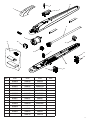
-
 1
1
-
 2
2
-
 3
3
-
 4
4
-
 5
5
-
 6
6
-
 7
7
-
 8
8
-
 9
9
-
 10
10
-
 11
11
-
 12
12
-
 13
13
-
 14
14
-
 15
15
-
 16
16
-
 17
17
-
 18
18
-
 19
19
-
 20
20
-
 21
21
-
 22
22
-
 23
23
-
 24
24
-
 25
25
-
 26
26
-
 27
27
-
 28
28
-
 29
29
-
 30
30
-
 31
31
-
 32
32


Beninca Bob Manuale utente
- Tipo
- Manuale utente
- Questo manuale è adatto anche per
in altre lingue
- English: Beninca Bob User manual
- français: Beninca Bob Manuel utilisateur
- español: Beninca Bob Manual de usuario
- Deutsch: Beninca Bob Benutzerhandbuch
- polski: Beninca Bob Instrukcja obsługi
Documenti correlati
-
 Beninca Bob 5024/Bob 5024E Guida utente
-
 Beninca MSE Guida utente
-
 Beninca Bob CS Manuale del proprietario
-
Beninca BOB5024 Manuale utente
-
 Beninca MATRIX and CP.BULL Manuale del proprietario
-
 Beninca CP.B24 Manuale del proprietario
-
 Beninca CP.B1024ESA Manuale utente
-
 Beninca CP.BULL Operating Instructions Manual
-
 Beninca ZEDL/ZEDLE Guida utente
-
 Beninca DU350CF Guida utente