Lindy 38281 Manuale utente
- Categoria
- Interruttori video
- Tipo
- Manuale utente
Questo manuale è adatto anche per

© LINDY Group - FIRST EDITION (September 2018)
Presentation Switch Pro with
HDBaseT Extender
User Manual English
No. 38281
lindy.com
Tested to Comply with
FCC Standards
For Home and Office Use!


User Manual English
Introduction
Thank you for purchasing the Lindy Presentation Switch Pro with HDBaseT Extender. This product has
been designed to provide trouble free, reliable operation. It benefits from both a LINDY 2 year warranty
and free lifetime technical support. To ensure correct use, please read this manual carefully and retain it
for future reference.
The Lindy Presentation Switch Pro is designed to allow many different video inputs including audio to be
switched and extended at the same time. It is an ideal addition to any meeting or conference room, lecture
hall or auditorium. For added flexibility the Switch is provided with a 70m HDBaseT Receiver to reach
remote displays and projectors.
Package Contents
▪ Presentation Switch Pro
▪ 70m HDBaseT Receiver
▪ Mounting ears
▪ Remote Control
▪ IR Receiver Cables
▪ IR Emitter Cables
▪ 1x 24V / 1A Power Adapter (5.5mm / 2.1mm) with UK, EU, AUS and US adapters
▪ 1x RCA x3 (Female) to VGA (Male) Cable
▪ This Manual
Features
• HDMI 2.0, HDCP 2.2 and 1.4 compliant
• DisplayPort 1.2a compliant
• Mirrored HDBaseT 70M output via included receiver
o 4K 30Hz, RGB, 8bit with 40m of Cat.6 cable
o 1920x1080, 60Hz, RGB, 8Bit with 70m of Cat.6 cable
o Dimensions: 115x17x65mm (4.53x0.67x2.56in)
• HDMI / DisplayPort video input resolution up to 4K 60Hz (4:4:4)
• VGA input resolution up to 1920x1200 60Hz
• Output of up to 4k 30Hz via local and remote HDMI
• HDBaseT receiver is powered by the transmitter using PoH
• Supports automatic and manual switching modes
• Supports EDID management
• Supports pass-through of PCM 2CH
• Control via Touch Panel buttons, Web GUI, IR remote, Terminal block contacts and RS-232

User Manual English
Specification
• Input ports: 3x HDMI 2.0, DisplayPort 1.2a and VGA, 5x Stereo Terminal blocks, 1x Mic Terminal
Block
• Output ports: 1x HDMI, 1x HDBaseT, 1x Stereo Terminal block
• Control Ports: 1x IR in, 1x IR out, 1x Contact Terminal block (6pin), 1x RS-232 terminal block, 1x RJ-
45, 1x USB Type A (firmware upgrade)
• Supports up to 18 Gbps / 600Mhz bandwidth
• Supported Resolutions
• HDMI / DisplayPort up to 3840x2160 60Hz 4:4:4 8bpc (30Hz output)
• VGA up to 1920x1200 60Hz
• HDBaseT up to 3840x2160 30Hz
• PCM stereo pass-through formats
• Optional phantom power for mic input
• HDCP 2.2 and 1.4 compatible
• Colour: Black
• Power Consumption: Main unit: 9W, HDBaseT Receiver: 9W
• Operating Temperature: 0°C - 40°C (32°F - 104°F)
• Storage Temperature: -20°C - 60°C (-4°F - 140°F)
• Relative humidity: 20 – 90% RH (non condensing)
Installation
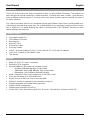
Front Panel:
Power button and indicator:
When this device is in standby mode the indicator will illuminate red. When switching the unit
on, the indicator will illuminate blue.
IR Window:
IR signal from remote control.
Input Source & Auto buttons:
Press these buttons for source selection.
The active source will be illuminated to corresponding indicator on the front panel.

User Manual English
Operation buttons:
• Pressing “OK/MENU” button enters the OSD. Then navigate using the 4-way arrow buttons.
A new OSD setting is confirmed by pressing the “OK/MENU” button.
• Pressing "EXIT/AUTO" will exit the OSD. Press "EXIT/AUTO" for 5 seconds to auto
switching on/off. When the button LED light is on, this means auto switching is on.
• Pressing the “MIC-/+” button decreases or increases MIC volume. Pressing the “VOL+/-“
button increases or decreases “Master volume”.
• Pressing both “MIC-“ and “MIC+” buttons simultaneously will reset the HDMI/HDBT output
resolution to 720P 60Hz.
• Pressing both “VOL-“ and “VOL+” buttons simultaneously will lock / unlock the front panel,
these two button LEDs will light on when the front panel is lock on.
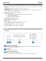
Rear Panel:
Control ports:
• LAN: This port is for Web GUI control; connect to an active Ethernet link with an RJ45
terminated cable.
• RS-232: Serial control port, connects with a control device to control the switch or it can be
used as an extender to control another device connected with the HDBaseT receiver.
• IR IN: Connect the IR receiver cable to receive IR signals sent by the IR remote or this can
be used to extend IR signals to the HDBaseT receiver.
• IR OUT: Connect the IR emitter cable. Used for controlling the local source device or the
switch.
• CONTACT IN: This input control is reserved for direct source selection. Connect the ground
pin (marked as on panel) with following pin number for individual source selection.

User Manual English
Pin number
Source
Pin 1
HDMI1
Pin 2
HDMI2
Pin 3
HDMI3
Pin 4
DisplayPort
Pin 5
VGA/YPbPr/CVBS
Audio Ports:
• OUT: The audio comes from the input audio corresponding to the selected video source and
mixed with MIC audio.
• HDMI1/2/3/DP: The external analog audio input for the respective input.
• VGA: The external analog audio input for the VGA input.
• MIC IN: Plug a microphone in to mix with the current audio source.
• PHANTOM ON/OFF: Slide the switch to “OFF” for a condenser or dynamic microphone, or
to “ON” for professional 48V phantom microphones.
Output Ports:
• HDBT Out: Connects to the HDBaseT Receiver with PoH functionality.
• HDMI Out: Connects to a HDMI display or AV Receiver for video and/or audio output.
Input Ports:
• These video input ports include 3 x HDMI inputs, 1 x Display Port input & 1 x VGA input. The
VGA port supports VGA, YPbPr and CVBS formats. The Factory default is VGA.
USB Port:
Reserved for future firmware upgrades
Power:
Plug the 24V DC power supply into the unit and connect the adaptor to an AC socket.

User Manual English
Operation
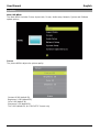
Main OSD MENU
The Main MENU includes Picture, Aspect ratio, Screen, Audio setup, Network, System and Software
update options.
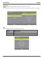
Picture
The picture MENU adjusts the picture quality.
Contrast 0-100 (default 50),
Brightness 0-100 (default 50),
Color 0-60 (default 30),
Sharpness 0-20 (default 10),
Tint 0-100 (default 50, for CVBS NTSC format only)

User Manual English
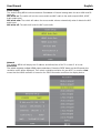
Aspect Ratio
Provides the ability to adjust the picture output aspect ratio to 4:3 or 16:9/10.
Screen
The screen MENU is only for the VGA input. You can adjust horizontal, vertical position, size and phase.
EDID
The EDID MENU adjusts HDMI and DisplayPort inputs only.
EDID1.4
4K2K30,PCM 2.0
EDID2.0
4K2K60,PCM 2.0
EDID From HDMI
EDID copy from local HDMI port
EDID From HDBT
EDID copy from HDBaseT Receiver HDMI port
EDID AUTO
Auto compare HDMI and HDBT Receiver HDMI port EDID

User Manual English
Audio Setting
The Audio Setting MENU switches between Embedded or External analog audio for each HDMI and DP
input port.
MIC mixer on: The switch will mix the source audio and MIC audio to the audio output (HDMI, HDBT,
Audio output port).
MIC mixer auto: The switch will reduce the source audio volume automatically when it detects the MIC
audio input.
MIC mixer off: The switch will mute the MIC input audio.
Network
The network MENU will display the IP address and allow either a DHCP or static IP to be set.
Resolution
The switch supports multiple HDMI output resolutions. Press the “RES” button on the IR remote, the
resolution menu will be displayed. Then select a suitable resolution for your HDTV or monitor. Auto
means that the HDMI resolution is based on the EDID information read from the display device.

User Manual English
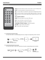
Remote Control
Power: Press this button to power on the switch or turn to standby mode.
INPUT: Press these buttons to select the input source.
ADJ: Press this button to operate the VGA input auto adjustment function
RES: Press this button to select the HDMI output resolution. (Press and
hold 5 seconds or more and the HDMI output resolution will reset to 720p
60Hz.)
Menu operation buttons:
MENU: Press this button to enter the OSD menu.
EXIT: Press this button to exit the OSD menu.
OK: Press this button to confirm the operation.
UP/DOWN/LEFT/RIGHT buttons: Selection operation.
VOLUME: Control master audio volume.
MIC: Control MIC input audio volume.
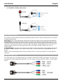
1) Control far-end device locally
To control the switch or a remote display device by using the corresponding remote controller.
2) Control local device from remote
To control the switch or local source device by using the corresponding remote controller.

User Manual English
3) IR (20KHz---60KHz) cable pinout
Auto-Switching function
The switch has auto-switching and manual-switching modes. When in auto-switching mode, it will follow
the following principles:
New input: Once a new input signal is detected, the switch will switch to this new signal automatically.
Power reboot: The switch offers the function to remember the signal last used before power off. Once
rebooted, it will automatically enter auto-switching mode, and then detect all inputs and memorise their
connection status for future reboots. If the last used input signal is still available, then it will choose that
signal. If not, it will detect all input signals with priority on HDMI1->HDMI2->HDMI3->DP->VGA
(YPbPr/CVBS).
Removed Signal: Once the current signal is removed, the switch will detect all input signals with priority
on HDMI1->HDMI2->HDMI3->DP->VGA (YPbPr/CVBS). It will transfer the first signal detected to the
output.
Notice: The Auto-switching function works only when there is a new input signal or if an input signal is
removed.
VGA/YPbPr/CVBS input
The VGA input port is a multiple format port. It supports VGA/YPbPr/CVBS input signals. The switch will
auto detect the input signal type and format. You can use the converter cable for YPbPr or CVBS signal
inputs.

User Manual English
Connection of Microphone
The switch provides one 2-level microphone input to accommodate different microphone input modes,
including 48V phantom power mode and MIC mode.
When switched to “ON” (It has a good frequency characteristics, high input impedance and high
sensitivity in this mode), the MIC input will provide 48V phantom power. This should only be used for
48V condenser microphones.
1) Unbalanced connection:
“+” and “ ” connect to ground, and “-” connects to signal.
“-” and “ ” connect to ground, and “+” connects to signal.
2) Balanced Connections: “+” connects to positive, “-” connects to negative and “ ” to ground.
When switched to “OFF” (It has low frequency characteristics and wide frequency response in this
mode), the microphone input is used for connecting dynamic and condenser microphones. There are two
different connections:
1) Unbalanced connection:
“+” and “ ” connect to ground, and “-” connects to signal.
“-” and “ ” connect to ground, and “+” connects to signal.

User Manual English
2) Balanced connection: “+” connects to positive, “-” connects to negative and “ ”connects to ground.
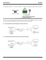
Operations of RS-232 Control
As RS-232 can be transmitted bi-directionally between the switch and the HDBaseT receiver, it is able to
control a third-party RS-232 device locally or control the switch bi-directionally.
1) Control the Switch or 3rd Party Device from the local side
2) Control the Switch or 3rd Party Device from remote Receiver

User Manual English
3) RS-232 Control
Please connect the switch with a computer that has been installed with the RS-232 control software. The
interface of the control software is shown as below:

User Manual English
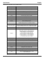
Custom serial commands are also available below:
Command
Description
help!
Display all communication commands
s factory reset!
Return to factory reset setting
r version!
Read current FW version
xyz!
Upgrade the switch FW
r power!
Read the switch power on/off status
s power on!
Power on the switch
s power off!
Power off the switch
r lock!
Read the switch panel lock status
s lock on!
Lock on the panel control
s lock off!
Lock off the panel control
s beep on!
Enable the switch Beep
s beep off!
Disable the switch Beep
r source!
Read current input source
s source 1!
Switch HDMI1 input(1:HDMI1,2:HDMI2,
3:HDMI3,4:DisplayPort,5:VGA/YPBPR/C-VIDEO)
r auto switch!
Read auto switch function status
s auto switch mode 1!
Enable auto switch function(1: Last connected source mode,
2: First connected source mode, 3: Priority source mode)
s auto switch off!
Disable auto switch function
r output!
Read output resolution
s output 1!
Setup output resolution at 3840x2160@30Hz
(1:3840x2160@30Hz,2:3840x2160@25Hz,
3:1920x1080@60Hz,4:1920x1080@50Hz,
5:1280x720@60Hz,6:1280x720@50Hz,
7:1920x1200@60Hz,8:1680x1050@60Hz,
9.1400x1050@60Hz,10.1360x768@60Hz,
11.1280x800@60Hz,12.1024x768@60Hz,
13.Out display EDID native resolution
r hdcp!
Read HDMI/HDBT output hdcp enable status
s hdcp bypass!
Set HDMI/HDBT output to hdcp pass through mode
s hdcp 1.4!
Set HDMI/HDBT output to hdcp1.4 version
r contrast!
Read picture contrast status
s contrast 0!
Setup picture contrast 0(range:0-100)
r brightness!
Read picture brightness status
s brightness 0!
Setup picture brightness 0(range:0-100)
r color!
Read picture color status
s color 0!
Setup picture color 0(range:0-60)
r sharpness!
Read picture sharpness status
s sharpness 0!
Setup picture sharpness 0(range:0-20)
r tint!
Read picture tint status
s tint!
Setup picture tint 0(range:0-100,for CVBS
NTSC format only)
r aspect ratio!
Read current input source output picture aspect ratio

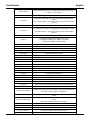
User Manual English
s aspect ratio 1!
Setup current input source output picture aspect ratio at 16:9
(1: 16:9 , 2: 4:3, 3:16:10 )
r h size!
Read current input source output horizontal overscan value
s h size X!
Set output horizontal over scan to (100+X)%(the default X
value
is 0 and the range is -10~10,the value is set for current input
source. )
r v size!
Read current input source output vertical overscan value
s v size X!
Set output vertical over scan to (100+X)%(the default X value
is
0 and the range is -10~10,the value is set for current input
source.)
r edid!
Read switch input port EDID status
s edid 1!
Setup input port EDID at HDMI1.4 standard
(1: EDID1.4,2:EDID2.0,3: EDID copy HDMI
4:EDID copy HDBT,5:EDID AUTO)
s vga auto!
Enable VGA auto adjust function
r vga hpos!
Read VGA horizonal position
s vga hpos up!
Setup VGA horizonal position up
s vga hpos up!
Setup VGA horizonal position down
r vga vpos!
Read VGA vertical position
s vga vpos up!
Setup VGA vertical position up
s vga vpos down!
Setup VGA vertical position down
r vga clock!
Read VGA input ADC sampling clock value
s vga clock up!
Increase VGA input ADC sampling clock value
s vga clock down!
Decrease VGA input ADC sampling clock value
r vga phase!
Read VGA picture phase
s vga phase up!
Setup VGA picture phase up
s vga phase down!
Setup VGA picture phase down
r mixer!
Read MIC mixer status
s mixer on!
Setup mic mixer on
s mixer off!
Setup mic mixer off
s mixer auto!
Setup mic mixer auto
s auto vol!
Set source audio volume when set to mixer auto mode
r auto vol!
Read source audio volume when set to mixer auto mode
r fade in time!
Read source audio fade in time when set to mixer auto mode
s fade in time 1000!
Setup source audio fade in time when set to mixer auto mode.
(The fade in time range is 0~5000ms.)
r fade out time!
Read source audio fade out time when set to mixer auto
mode
s fade out time 1000!
Setup source audio fade out time when set to mixer auto
mode
(The fade out time range is 0~5000ms.)
r out vol!
Read output audio volume
s out vol 0!
Setup output audio volume 0(0~32)
s out vol up 1!
Increase output audio volume 1 level
s out vol down 1!
Decrease output audio volume 1 level
r mic vol!
Read mic volume

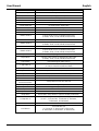
User Manual English
s mic vol 0!
Setup mic volume 0(0~32)
s mic vol up 1!
Increase mic input audio volume 1 level
s mic vol down 1!
Decrease mic input audio volume 1 level
s mic mute on!
Mute mic input audio
s mic mute off!
Un-mute mic input audio
s audio mute on!
Mute source input audio
s audio mute off!
Un-mute source input audio
s mute on!
Mute source and mic input audio
s mute off!
Un-mute source and mic input audio
r hdmi1 audio!
Read HDMI1 audio source
s hdmi1 auido 0!
Choose audio source as HDMI1 audio input
(0: Emb,1: Ext1,2: Ext2,3:Ext3,4:Ext4,5:Ext5)
r hdmi2 audio!
Read HDMI2 audio source
s hdmi2 auido 0!
Choose audio source as HDMI2 audio input
(0: Emb,1: Ext1,2: Ext2,3:Ext3,4:Ext4,5:Ext5)
r hdmi3 audio!
Read HDMI3 audio source
s hdmi3 auido 0!
Choose audio source as HDMI3 audio input
(0: Emb,1: Ext1,2: Ext2,3:Ext3,4:Ext4,5:Ext5)
r dp audio!
Read Displayport audio source
s dp audio 0!
Choose audio source as Displayport audio input
(0: Emb,1: Ext1,2: Ext2,3:Ext3,4:Ext4,5:Ext5)
r vga audio!
Read Displayport audio source
s vga audio 1!
Choose audio source as VGA audio input
(1: Ext1,2: Ext2,3:Ext3,4:Ext4,5:Ext5)
r ip mode!
Read IP mode
s ip mode 1!
Setup IP mode at Static (1:Static,2:DHCP)
r ip addr!
Read IP address
s ip addr 192.168.1.255!
Setup IP address at 192.168.1.255
r subnet!
Read subnet
s subnet
255.255.255.252!
Setup subnet at 255.255.255.252
r gateway!
Read gateway
s gateway 192.168.1.1!
Setup gateway at 192.168.1.1
r port!
Read control port
s port 8000!
Setup control port at 8000
r sleep time!
Read switch sleep time(no signal to standby mode time)
s sleep time 1!
Set switch sleep time(no signal to standby mode time)
(1: OFF , 2: 15seconds, 3: 1minutes ,4: 5minutes,
5:15minutes, 6: 60minutes)
r osd time!
Read OSD time out
s osd time 1!
Set OSD time out
(1: 5seconds, 2: 10seconds,3: 15seconds ,
4: 20seconds, 5: 25seconds , 6: 30seconds )

User Manual English
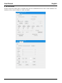
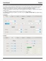
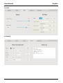
Web GUI Control
The switch can be controlled via a Web browser, which contains General, Setup and Network Settings.
After the active Ethernet link with a RJ45 cable is connected, the IP address is entered in the Web
browser. If the IP address is unknown, there are two methods to obtain the IP address.
1. Obtain the IP address and port number via the information from the MENU-> Network OSD using the
remote control.
2. Obtain the IP address and port number via the RS-232 Control software.
For example, the obtained IP address is 192.168.1.100. Input http://192.168. 1.100 in the address bar of
the web browser.
1) General
2) Video

User Manual English
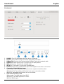
3) Audio
4) Network

User Manual English
5) Advanced
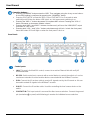
HDBT Receiver
1. POWER: This LED illuminates when the device is powered
2. DC 24V: Not needed if using PoH remote power from transmitter
3. HDBaseT IN: Connect from the transmitters HDBaseT port with a network cable
4. HDMI OUT: HDMI output port for connection to the display device.
5. IR IN: IR Receiver. Connect with included cable.
6. IR OUT: IR Transmitter. Connect with included cable.
7. RS-232: Phoenix jack, provides Serial port control signal from receiver or to receiver.
8. Connection Signal Indicator Lamp
※Illuminated: The Transmitter and Receiver have a good connections status.
※Flashing: The Transmitter and Receiver have a poor connections status.
※Off: The Transmitter and Receiver are not connected.
9. Data Signal Indicator Lamp
※Illuminated: The HDMI signal has HDCP.
※Flashing: The HDMI signal has no HDCP.
※Off: No HDMI signal
La pagina sta caricando ...
La pagina sta caricando ...
-
 1
1
-
 2
2
-
 3
3
-
 4
4
-
 5
5
-
 6
6
-
 7
7
-
 8
8
-
 9
9
-
 10
10
-
 11
11
-
 12
12
-
 13
13
-
 14
14
-
 15
15
-
 16
16
-
 17
17
-
 18
18
-
 19
19
-
 20
20
-
 21
21
-
 22
22


Lindy 38281 Manuale utente
- Categoria
- Interruttori video
- Tipo
- Manuale utente
- Questo manuale è adatto anche per
in altre lingue
- English: Lindy 38281 User manual
- français: Lindy 38281 Manuel utilisateur
Documenti correlati
-
Lindy 2 Port HDMI & VGA to VGA Audio Switch Manuale utente
-
-
-
-
-
-
-
-
-
Altri documenti
-
Cables to Go 30012 Manuale del proprietario
-
ATEN CE924 Guida Rapida
-
-
NEC NP01SW1 Manuale del proprietario
-
-
Analog way Saphyr-H Manuale utente
-
-
Legrand HDMI HDBaseT Extender over Cat Box Transmitter to Box Receiver - 4K 60Hz Manuale del proprietario
-
Planar UR8451-LX-Touch Manuale utente
-
Eiki EK-600U Manuale utente