
Type 8017
Cod. S6I.801.70E RL. 00 11/2007
Il prodotto è conforme alla direttiva europea 89/336/CEE e successive.
Product is according to EC Directive 89/336/EEC and following norms.
CONNECTION MANUAL
“KEYPAD ENCODED WITH TOUCH KEYS”
(ALPHANUMERICAL)

2
GENERAL OPERATION:
The board , (equipped with an alphanumerical display with 2 lines x 16 characters) manages up to 4 different access points for
“TOUCH KEY” type readers. Each access point can activate a different relay connected directly to the board “ locally” (the first
output already has an “on-board” relay), and simultaneously/when necessary to enhance safety, an external relay connected
“remotely” by means of a serial bus (with type 170D-170F or similar).
Each of the 4 output (to relays) can operate in various modes (timed, on/off, combined, etc) with time intervals settable from 1
and 255 seconds or from 1 minute to 255 minutes.
The control unit memorises up to 500 “TOUCH KEYS“ (expandable on request to over 2000 users), managing different priorities
and permissions for each user (on the 4 outputs).
At the same time, 100 different 8-digit digital codes can be memorisedto be used as passwords, directly on the control unit key-
pad.
If equipped with a clock module, the control unit also enables each opening operation to be recorded (within an internal list of
500 cycles). This list can be downloaded if required onto PC by means of the specific interface.
The control unit, featuring total autonomous use, can also be interfaced with the “Digibus” systems and/or a PC both for code
programming and the remote management of an entire access control system.
made in ITALY
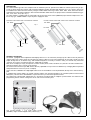
R
CN4
PROGRAM
T2
4
T3
T4
T1
S4
S3
S2
RB
RA
1
4
5
Art. 8017
RESET
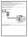
Top: terminal boards. <- Left: Code reader contact
(“PROBE”). Right: Encoded digital codes (“Touch keys”). ->
DESCRIPTION
The control module type 8017 is a component for the modular system of panels series 8000. The entrance panels may be pre-
set for the flush-mounted or surface wall-mounted installation, possible provided with rainproof cover. The entrance panel may
be installed in the flush-mounted version by using the module holder frames type 8D81, 8D82, 8D83, 8D84, and in the surface-
wall mounted version using, besides the abovementioned module holder frames, the proper surface wall-mounted back box (type
9411, 9412, 9413, 9414) (See fig. 1).
The 8017 module is equipped with an output with relay for the lock release and 3 (additional) open-collector output for the con-
trol of relay type 170/001. Module require an power supply Art. 6582
ENTRANCE PANEL SERIES 8000, FLUSH-MOUNTED VERSION.
ENTRANCE PANEL SERIES 8000, SURFACE WALL-MOUNTED VERSION.
Fig. 1
Art. 8D8x
Art. 909x
Art. 92xx
Art. 8D8x
Art. 94xx
Art. 92xx

3
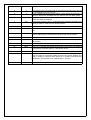
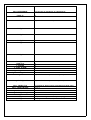
TERMINAL DESCRIPTION
5 Positive power supply at 11-16 Vdc (typically 12-13Vdc)
4 Negative (earth). The terminal is duplicated on two terminals.
1 Digital. Used for interfacing other devices, when required (e.g. 170D -F) or for PC interface
(data download, access supervision or programming). Connected by means of a resistance
(820 ohm, removable) to an internal positive (12 Vdc, ~14mA)
RA-RB Output n°1. Normally associated with a TOUCH1 reader. Corresponds to two
“voltage free ” contacts (normally open) of an internal relay (max0.5/1 A).
S2 Output n°2. Normally associated with a TOUCH2 reader. This is an “open-collector” output, i.e.
is earthed when activated (positive is external). To activate an external relay connect between
this terminal and terminal 5 (+12)
S3 Output n°2. Normally associated with a TOUCH3 reader. This is an “open-collector” output, i.e.
is earthed when activated (positive is external). To activate an external relay connect between
this terminal and terminal 5 (+12)
S4 Output n°2. Normally associated with a TOUCH4 reader. This is an “open-collector” output, i.e.
is earthed when activated (positive is external). To activate an external relay connect between
this terminal and terminal 5 (+12). As above but for touch 4
This is an “auxiliary” output as it can also be associuated with activation of the other 3 codes.
It is usually used for the accessory control of the courtesy light (activated together with the first
3 locks but at specific time intervals).
T1 Positive to connect to “probe” of touch number 1. The touch reader is connected between this
terminal (white wire) and earth (black wire). Multiple readers can be connected in parallel (all
with the same functions).
T2 Positive to connect to “probe” of touch number 2. The touch reader is connected between this
terminal (white wire) and earth (black wire). Multiple readers can be connected in parallel (all
with the same functions).
T3 Positive to connect to “probe” of touch number 3. The touch reader is connected between this
terminal (white wire) and earth (black wire). Multiple readers can be connected in parallel (all
with the same functions).
T4=CN4 Positive to connect to “probe” of touch number 4. The touch reader is connected between this
terminal (white wire) and earth (black wire). Multiple readers can be connected in parallel (all
with the same functions).
In this case the touch must be connected by means of a specific 2-pole connector.
TERMINAL BOARD LAYOUT:
The control unit has the following terminals: - 4 terminals for the connection of 4 code reading contacts (“probes”). The terminals
are marked T1 , T2, T3, T4 (the latter on a strip connector for local connection). NB: Connect the grey wire of the “probe” to ter-
minal T1-2-3-4 and the black wire to an earth terminal (4).
- 1 double terminal for output 1 , connected to the contacts of a N.O. type internal relay (terminals RA and RB) - 3 pilot outputs
for the same number of relays referable to outputs 2,3 4. (terminals S2, S3, S4)
- 2 12-16Vdc power supply terminals (terminals 4=GND, 5=+12) - Terminal 1 for digital communication (optional connection).

4
DIP-SWITCH BLOCK:
This enables blocking, in manual mode (Hardware) of programming/modification/deletion of internal codes. To activate
programming, both switches must be set to OFF (if just one of the two is ON, programming is inhibited).
PROGRAMMING THE TOUCH KEYS:
NB: the memorisation procedure must be performed with the probe connected to T1.
1) Press keys “R”+”7” together (NB: first R and then 7 with the 2 rear switches set to OFF). This displays :
2) Enter the correct password (by default 222) and press “C” to confirm (as indicated on display). If correct, access is gained to
key programming.
3) The display then shows (Programming of the first touch key in the list). Then use the (right arrow) cursors
to scroll to the required position and press “C”. For faster access, enter the number of the required position and press “C”.
4) This then flashes on display (alternating with the key number) , on standby for the code to be programmed
to be placed on the “probe”.
5) Depending on requirements, the following is possible:
a) When the key is placed on the probe the new key is memorised. Memorisation is confirmed by a short tone and a memo mes-
sage. ->
b) Press “0” to cancel the relative key in the memory.
c) Press “R” to exit the key programming procedure.
d) Enter “9999” to start overall deletion of all keys.
e) Press “
*
” for access to programming of accessory parameters: priorities, selection of keys on which to be active, type of key.
See below for these programming procedures.
6) In the standard case of memorisation, after a brief interval Type 8017 returns to point 3 in preparation to acquire new subse-
quent keys.
PROGRAMMING ACCESSORY PARAMETERS (FOR EACH KEY):
In the case of programming accessory parameters (by pressing “
*
” as in point 5 above) the following options can be set: -
Activation of the key only on some of the 4 probes (readers). By default each key is valid on all 4 reader inputs (touch). -
Modification of key priority between 0 and 15 (currently set at 7). This second function only serves for special management
modes (timed) by computerised systems.
7) To set these parameters, after pressing “
*
” the following message is displayed: in practice this message indi-
cates that the selected key is active on all 4 outputs (1111). Each number 1 corresponds to an active key, and 0 to a deactiva-
ted key. The first 1 on the left corresponds to reader 1, the second to reader 2, then 3 and the last 1 to reader 4. To modify the
enabled/disabled status, rewrite the 4 digits using 1 for active status and 0 on those to be disabled (per key). E.g. to activate it
only on key 1 enter 1000 , to activate it on 2 and 4 enter 0101….
Press “C” to confirm.
8) The following message is then displayed:
The message indicates that the key has a priority setting of 7. Enter the new priority level (or leave unchan-
ged) and press -“C”. Modifications to the priority level is only useful for special applications (timed).
Press “C” to confirm (with message) and exit the setting procedure and return to point 3.
TOUCH INPUT OPERATING MODES:
The control unit is fitted with 4 different inputs (T1,T2,T3,T4) for key reading (“probes”). Each of these 4 inputs is associated with
one of the 4 outputs (OUT1,2,3,4) to which a different device can be connected (usually a lock or light). Therefore, for example,
if the key is read on probe n°1, and on verification that it is stored and active on this input (accessory parameter), the corre-
sponding output 1 is activated.
In this way a single control unit enables control of up to 4 different access points.

5
For each of the 4 outputs, the following operating modes can be programmed: - Timed operation : On each reading of the key,
the output is activated for the time set in the memory (from 1 to 2550 sec). When this time interval elapses, the output is auto-
matically deactivated.
- ON/OFF operating mode: on the first reading, the relative output is activated, and on the subsequent reading is deactivated
(however the maximum time interval set in the memory remains valid).
For the first 3 outputs it is also possible to simultaneously activate output 4 (according to the relative set time interval). This may
be useful, for example, to open the door for 1 second and simultaneously turn on a common light for 2 minutes.
Combined functions between “probes” 1 and 2 or between 3 and 4 may also be enabled. For example, “probe” 1 may activate
an output and probe 2 could deactivate it.
For each of the 4 inputs, a simultaneous command can be enabled (on the “digital” line) (programmable) to enable the activa-
tion of a remote command (of example via a digital relay 170D activation of a lock not controllable by the control unit).
At the same time as activation of each output the display shows information messages (accompanied by acoustic signals) indi-
cating the type of operation, recognition of the key and the position of the key in the list.
TOUCH KEY MANAGEMENT:
The control unit manages (as standard) 500 “TOUCH” keys. A priority level is also memorised for each key, and the relative per-
missive for the 4 different outputs (i.e. keys may be set to open only specific locks of the 4 available). In programming mode, the
user can scroll through the keys on display, with direct access to each one of the 500 keys, display of the associated parame-
ters, modifications, deletion and entry of individual keys. Complete deletion of all keys is also possible. These operations can be
performed either via the keypad (operations protected by “R4” + password , and for further safety also an optional microswitch
mounted inside the board) or via the special PC software.
CONFIGURATION AS ACCESS CONTROL:
Each control unit is programmable with a special code (“Digibus number” parameter) and controllable “on the network” by means
of a specific 2+1 wire BUS . In this way, one or more remote units (normally PCs)can be used to record all openings, modify per-
missive of single control units or individual users, modify priority levels, and update/download/upload utilities.
KEY PROGRAMMING AND OPERATION VIA THE KEYPAD:
The control unit enables, in addition to the use of touch-keys, management of an access point via the KEYPAD. This can memo-
rise 100 different 8-digit codes usable to activate relay output n°1. Operation and programming of these codes is the same as in
the case of the digital panel (digibus). The key action modes are the same as those of touch1. In practice opening is activated
on output 1 with the relative time intervals and functions.
NB: For special application, the 2 effects of keypad keys and touch keys can be combined. To do this, connect the relay to be
activated between the relay out1 (connected to +12 on one side) and output 2. Program the time of output 2 to enable entry of
the code on the keypad (15-30 seconds). Leave time 1 normally at approx. 1 sec. In this way, after placing the touch key on probe
2 enter the code on the keypad. The relay is only activated if both are valid.
NB2: All codes entered and not recognised are in any event sent (with the command “NOOPEN_SERR”) to the digital bus ( com-
bining them with the specific digibus number). This means they can be used to activate other additional devices by means of
types 170D-170F.
To effect a door lock release:
With display viewing:
<<<ß-------------à>>>
Enter code
(if not press first push-button “R”), to release the door lock enter one of the codes recorded in parameters from number xx to yy
and then press push-button “C”.
Attention: code 0 is not a number to be used to release the door lock.
To store the door codes, proceed as it follows:
- Enter the technical programming (push-buttons R + 4), then digit the programming “password” (default value: 123). NOTE:
first of all make sure the lock dip-switches (on the rear) are not in ON position (BLOCK.PRG).
- Scroll all parameters until you reach the key zones (on display appears the following message “CHIAVE Ser. N 001”). NOTE:
To by-pass all the parameter scrolling, press the “double arrow down” in order to reach the first key immediately).
- Scroll until you reach the key position to enter/modify (for example: “Chiave Ser. N 015” for the 15th key ).
- Enter the code to store (without initial zeroes and with a maximum of 8 digits).
- Confirm with push-button “C” to store it.
To exit the programming, press the “R” push-button.
Manual output time 4: This is the activation time of output 4 when activated directly by terminal T4 (closing to earth). This func-
tion is only useful in this specific operating mode (see below “operating mode”=64) and for output 4 only.

6
Command TX Output1-2-3-4Aux: Enables the association, for each of the 4 outputs, of a different digibus command to send on
the digital line, at the same time as activation of the corresponding touch key. This enables activation of “remote” relays placed
even far from the control unit (up to 1 Km directly, and more with repeaters). The activation of these relays is by means of digi-
tal codes, enabling the total inhibition of lock opening even in the event of tampering with the control unit. The commands can
also be used for remote recordings (from PC ) of accesses.
For the correspondence between codes and commands, see appendix A.
MAIN PROGRAMMING PARAMETERS (details):
TOUCH mem. key: (touch programming key): this is the password to enter and enable the entry or deletion of keys from the con-
trol unit (after pressing keys R+7 together and excluding the block by means of the dip-switches) . By default this is 222. Settable
between 1 and 9999.
Key 0, R-1, C: (lock release code). In the same way as the version for digibus panels, this enables access to key opening via
the keypad, by pressing R+1, 0 or C. In addition, if set to 4 (default) opening of the key can be performed directly (by entering
the code directly and pressing C)
Output 1-2-3-4 Time (Aux): Enables entry of the activation times of the 4 outputs (1-2-3 and AUXILIARY=4). Settable between 1
and 255 seconds. Times can be increased by adding the multiplcator x minutes (see below), to enable time intervals up to 255
minutes.
Op. Mode Out. 1-2-3-4: Enables the settings, of each of the 4 outputs of different operating modes (timed, ON-OFF, combined
on output AUX, combined).
To activate the following special functions, proceed as follows (add together if more options are required ): 0= normal mode
(timed)
1=Enables the simultaneous activation of output AUXILIARY 4 (based on set times). In this case, for example on output 1, the
relative lock can be activated for 1 second and the stair light for 2 minutes.
2= On activation of the corresponding output, activates delivery on the serial line of the relative associated Digibus code (for acti-
vation of “remote” relays.
4=Activates the ON-OFF mode. On the first reading of a key, the corresponding output is activated, and on subsequent reading
it is tuned off. NB: the set times also remain valid in this mode, i.e. after the time interval elapses the output turns off automati-
cally (if automatic shutoff is not required, set the time to 255 minutes (over 4 hours).
8=Activates combined use of T1 and T2 or T3 and T4. The first touchkey activates the corresponding output (1 or 3) and the
second touchkey deactivates it.
16=Activates the time intervals in minutes. The set time on the corresponding output is calculated in minutes instead of seconds.
32=Activates the request on the keypad: after recognition of the “touchkey” no output is activated but the display shows the
request which output is to be activated. Keys 1 to 4 activate the corresponding output, while keys 5 to 9 send different digital
commands for “remote” activation. In this way a single reading “probe” can activate up to 9 different devices.
64=Activates input operation in “manual” mode (keys). In this case the input no longer considers the connection of a touchkey,
but operates as a key contact: the relative output is activated when the specific terminal is shorted to earth by an external key
(for at least 2-300 ms). Useful for timed stair lights not dependent on touchkeys.
128= Activates the day/night control for the auxiliary light. In this case the light (connected to the auxiliary output) will only be
activated during the day. The function is only significant if the internal clock is fitted (optional).
Some typical examples of programming MOD_OUT1-2-3-AUX:

7
MODE VALUE SET TOTAL EFFECT
0 0 The output functions in timed mode (is activated and remains active only for
the corresponding set time interval)
1 1 As per 0 (above) but also activates output 4 (with specific time interval). In
practice 2 devices are activated with time intervals that can differ greatly
2 2 As per 0 but also transmits the programmed code on the serial line (for
remote activations/recordings)
3 2+1 Combination of points 2 and 1. Timed output with activation of output 4 and
delivery of code on serial line (for remote control).
4 4 ON-OFF mode
5 4+1 4+1 As per 4+1. ON-OFF mode with timed simultaneous activation of out-
put 4.
7 4+2+1 4+2+1 As per 4+2+1. ON-OFF mode with timed simultaneous activation of
output 4 and delivery of command on serial line (for remote control).
8 8 Combined mode. Uses 2 touchkeys for output 1 (separate ON and OFF)
16 16 As per 0 but the programmed times are in minutes instead of seconds (max
255 minutes)
17 16+1 As above but also activates output 4 (with specific times).
32 32 Activates the request of the output number to be activated.
33 32+1 As per 32+1: Activates the request of the output number to be activated and
simultaneously activates output 4 ( with specific times)
48 32+16 As above, but the times are in minutes on the corresponding output.
64 64 Enables operation as manual key. The relative terminal of the touchkey no
longer functions as a touchkey reader but as an NO contact. Relative acti-
vation is simply by closing to earth (terminal 4). Enables timed accessory
pushbuttons. The function is not valid for touch 1 terminal.
128 128 Activates the day-night operating mode for the service light (S4).

8
Key oper. mode (KEYPAD MODE): Enables activation and setting of keypad use for lock opening. If set to 1 the keypad acts on
output 4, 2 on 3, 4 on 2, and 8 on 1. For special applications, this can also enable the entry of lock priorities (add together the
value=priorityx16).
INTERNAL CLOCK: The control unit can optionally be equipped with an internal clock module (for recording access times, light
timing and timed activation cycles).
RECORDING ACCESSES ON INTERNAL MEMORY:
The control unit keeps track, on the internal memory, of the last 500 activation cycles. For each of these, it memorises the type
of operation, some accessory information and the time of activation (if the clock is fitted, otherwise based on an internal coun-
ter).
To view the data, it must be “downloaded ” onto PC (by means of the interface 6952 and the software supplied). The procedure
is similar to that performed for programming (with the same software, started up in “view accesses” mode).
Type 8017 can be interfaced by means of the special PC software equipped with the interface type 6952. The software, named
“ELVOX - DATA ORGANIZER” (configurable also for other devices) enables execution of the following main functions: Intuitive
and fast use thanks to the evolved graphic interface (similar to “Windows”).
SOFTWARE FOR PROGRAMMING VIA PC:

9
Entry, deletion and modification of one or more users.
- Registration of new keys. Modification of associated parameters (priority and activation settings).
- Storage of data and recovery on specific files on the PC.
- Associations with keys of the names of persons using them (the data is stored on the PC and not on the control unit).
- Safety: in the event of damage to the switchboard, data can be restored at any moment with no waste of time.
- Possibility of repeating the same programming for multiple control units without having to re-enter the data-base.
- Reading of data by switchboard with recovery also of data entered manually.
- Possibility of entering additional information as a description (notes) [to be completed]
- Registration, modification and deletion of key list “from keypad”.
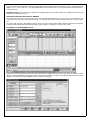
CONNECTION OF PC FOR DATA DOWNLOAD/UPLOAD:
This is performed by means of the specific interface (type 6952) connected to the COM port of the PC as shown in the example
below (NB: in this case the panel is type 8017).
ma de in IT ALY
R
CN4
PROGRAM
T2
4
T3
T4
T1
S4
S3
S2
RB
RA
1
4
5
Art. 8017
RESET
Art.
6952
Interfaccia seriale
serial interface
madeinITALY
R
The connection between the PC and device is by means of the interface connected with just wires as described above.
APPENDIX A: “KEY TO DIGIBUS CODES“
The following lists the main useful codes. If associated with the touchkeys and sent to activate external devices (by means of
170D or 170F) use codes that do not interfere with operation (normally codes F1…F8). Note that if different commands are sent
undesired operating modes may occur.
N.B. Avoid other digital
objects in parallel on this
connection.
GND
RX Led lit if con-
nection ok
Art. 8017

10
APPENDIX A TABLE
CALL INTERPHONE 32 (call from an interphone to switchboard)
FUNZ_F2 40
LOCK 36 (lock release command)
FUNZ_F1 34
FUNZ_F3 41
FUNZ_F4 42
FUNZ_F5 43
FUNZ_F6 44
FUNZ_F77 45
FUNZ_F78 46
F_ALARM 50
F_STOP_ALARM 51
F_ACTIV_DEVICE 52
F_DISACTIVE_DEVICE 53
CALL_PANEL 33 ("audio" call from panel to interphone)
CALL_SELFST_PANEL 49 ("video" call from panel to interphone)
CALL_PANEL+TLC 161 (similar to above but for intercommunicating calls)
CALL_PANEL+INTERC 177 (" ")
CALL_PANEL+TLC+INTERC 73
CALL_SELFST_PANEL_TLC 74
LOCK_BACK 75 (lock release backwards)
ENTER_PRG 120 (when setting??? the interphone prog.)
NOOPEN_LOCK 123 (key entered not found)

11
ART. 8017
WORKING MODIFICATION OF THE KEYBOARD KEYS
Following up the software version issued after 28/03/2006 (that can be noticed on the panel by pressing “R+9” keys) it is possi-
ble to enable the codes from the keyboard so that the 4 exits can be activated independently. By means of this function it is pos-
sible to control 100 codes stored with different functioning as regards the activated exit (among the 4 ones available). For this
reason when you store the key codes (in the programming phase after having pressed “R+4”) the following message is displayed
(related to the first key stored in case the code 123456 has been already assigned)
00123456 0 0
Key code N001
By selecting the new code and confirming the same by pressing “C” it is possible to modify it as before.
If you leave the numbers on its right unchanged ( equal to 0 0) the unit works as before, that is to say by selecting the code
(123456) it opens the connected exit according to the parameter “Key Function Mode” (by default exit no.1 is enabled).
In case you wish that one key activates another exit (example exit no.3)
you must modify the first number after the code (0) by pressing “*” key several times (values from 1 to 7 will be displayed in
sequence and then will return to 0). As a consequence of this value, when inserting relevant code, the exit will be activated accor-
ding to the table here below:
0 The exit will be enabled by default (according to the parameter set in the “Key Function Mode”)
1 Exit No.1 (RA-RB)
2 Exit No.2 (S2)
3 Exit No.3 (S3)
4 Exit No.4 (S4)
5 Digital code F6 is sent for remote functions
6 Digital code F7 is sent for remote functions
7 Digital code F8 is sent for remote functions
In case you wish to enable exit no.3 using the first code (equal to 123456) then the following message will be displayed
00123456 3 0
Key code N001
N.B.: By pressing “^” key subsequently (arrow up) it is possible to modify the value according to 0 (values between 0 and 3). By
means of this function it is possible to modify the working time in case module type 8017 is supplied complete of internal clock
(available on request and not supplied as standard facility). When you do not use this function then the parameter must remain
equal to 0 (always enabled independently from the clock).

12
FILIALE DI MILANO:
Via Conti Biglia, 2 20162 (MILANO)
Tel. 02/6473360-6473561
Fax 02/6473733
E-mail: [email protected]
FILIALE TOSCANA:
Via Lunga 4/R 50142 FIRENZE
Tel. 055/7322870 - Telefax. 055/7322670
E-mail: [email protected]
UNI EN ISO 9001
ELVOX COSTRUZIONI
ELETTRONICHE S.p.A.
35011 Campodarsego (PD) - ITALY
Via Pontarola, 14/A
Tel. 049/9202511 r.a. -
Phone international... 39/49/9202511
Telefax Italia 049/9202603
Telefax Export Dept... 39/49/9202601
ELVOX INTERNET SERVICE
E-mail: [email protected]
http://www.elvox.com
E-mail export dept:
SAFETY INSTRUCTIONS FOR INSTALLERS
- Carefully read the instructions on this leaflet: they give important information on the safety, use and maintenance of the instal-
lation.
- After removing the packing, check the integrity of the set. Packing components (plastic bags, expanded polystyrene etc.) are
dangerous for children. Installation must be carried out according to national safety regulations.
- It is convenient to fit close to the supply voltage source a proper bipolar type switch easy accessible with 3 mm separation (min-
imum) between contacts.
- Before connecting the set, ensure that the data on the label correspond to those of the mains.
- Use this set only for the purposes designed, i.e.for electric door-opener systems. Any other use may be dangerous. The man-
ufacturer is not responsible for damage caused by improper, erroneous or irrational use.
- Attention: to avoid hurting himself, this appliance must be fixed to the soil/wall according to the installation instructions.
- Before cleaning or maintenance, disconnect the set.
- In case of failure or faulty operation, disconnect the set and do not open it.
- For repairs apply only to the technical assistance centre authorized by the manufacturer.
- Safety may be compromised if these instructions are disregarded.
- Do not obstruct opening of ventilation or heat exit slots and do not expose the set to dripping or sprinkling of water.
- Installers must ensure that manuals with the above instructions are left on connected units after installation, for users' infor-
mation.
- All items must only be used for the purposes designed.
- The installer must make sure that the information for the user be present with the appliances.
- This leaflet must always be enclosed with the equipment.
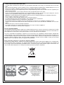
Directive 2002/96/EC (WEEE)
The crossed-out wheelie bin symbol marked on the product indicates that at the end of its useful life, the product must be hand-
led separately from household refuse and must therefore be assigned to a differentiated collection centre for electrical and elec-
tronic equipment or returned to the dealer upon purchase of a new, equivalent item of equipment.
The user is responsible for assigning the equipment, at the end of its life, to the appropriate collection facilities. Suitable diffe-
rentiated collection, for the purpose of subsequent recycling of decommissioned equipment and environmentally compatible treat-
ment and disposal, helps prevent potential negative effects on health and the environment and promotes the recycling of the
materials of which the product is made. For further details regarding the collection systems available, contact your local waste
disposal service or the shop from which the equipment was purchased.
Risks connected to substances considered as dangerous (WEEE).
According to the WEEE Directive, substances since long usually used on electric and electronic appliances are considered dan-
gerous for people and the environment. The adequate differentiated collection for the subsequent dispatch of the appliance for
the recycling, treatment and dismantling (compatible with the environment) help to avoid possible negative effects on the envi-
ronment and health and promote the recycling of material with which the product is compound.
-
 1
1
-
 2
2
-
 3
3
-
 4
4
-
 5
5
-
 6
6
-
 7
7
-
 8
8
-
 9
9
-
 10
10
-
 11
11
-
 12
12


