EPOX EP-MVP4G Manuale utente
- Categoria
- Schede madri
- Tipo
- Manuale utente
Questo manuale è adatto anche per

TRADEMARK
All products and company names are trademarks or registered
trademarks of their respective holders.
These specifications are subject to change without notice.
Manual Revision 6.0
September 17, 1999
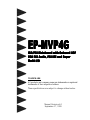
EP-MVP4GEP-MVP4G
EP-MVP4GEP-MVP4G
EP-MVP4G
ISA/PCI Mainboard with Onboard AGPISA/PCI Mainboard with Onboard AGP
ISA/PCI Mainboard with Onboard AGPISA/PCI Mainboard with Onboard AGP
ISA/PCI Mainboard with Onboard AGP
VGA PCI Audio, PCI IDE and SuperVGA PCI Audio, PCI IDE and Super
VGA PCI Audio, PCI IDE and SuperVGA PCI Audio, PCI IDE and Super
VGA PCI Audio, PCI IDE and Super
Multi-I/OMulti-I/O
Multi-I/OMulti-I/O
Multi-I/O

EP-MVP4G
User Notice
No part of this product, including the product and software may be reproduced,
transmitted, transcribed, stored in a retrieval system, or translated into any
language in any form without the express written permission of EPoX Computer
Company (hereinafter referred to as EPoX) except for documentation kept by the
purchaser for backup purposes.
We provide this manual “as is” without warranty of any kind, either expressed or
implied, including but not limited to the implied warranties or conditions of
merchantability or fitness for a particular purpose. In no event shall EPoX be
liable for any loss of profits, loss of business, loss of use or data, interruption of
business or for indirect, special incidental, or consequential damages of any kind,
even if EPoX has been advised of the possibility of such damages arising from any
defect or error in the manual or product. EPoX may revise this manual from time
to time without notice. For updated BIOS, drivers, or product release information
you may visit our websites at http://www.epox.com or http://www.epox.com.tw.
Products mentioned in this manual are mentioned for identification purposes only.
Product names appearing in this manual may or may not be registered trademarks
or copyrights of their respective companies. The product name and revision
number are both printed on the mainboard itself.
Handling Procedures
Static electricity can severely damage your equipment. Handle the EP-MVP4G
and any other device in your system with extreme care and avoid unnecessary
contact with system components on the mainboard. Always work on an antistatic
surface to avoid possible damage to the mainboard from static discharge. Always
have the power supply unplugged and powered off when inserting and removing
devices within the computer chassis. EPoX assumes no responsibility for any
damage to the EP-MVP4G mainboard that results from failure to follow instruc-
tion or failure to observe safety precautions.
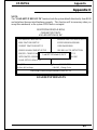
CAUTION
The EP-MVP4G mainboard is subject to
damage by static electricity. Always
observe the handling procedures.

EP-MVP4G
Technical Support Services
If you need additional information, help during installation or normal use of this
product, please contact your retailer. Your retailer will have the most current
information about your configuration. If your retailer cannot help, you may visit
our online technical support website and/or contact our support technicians at the
locations listed below.
Record your serial number before installing your EP-MVP4G mainboard. (The
serial number is located near the PCI slots at the edge of the board.)
EP-MVP4G serial number: _________________________________
Contacting Technical Support
EPoX technical support is working hard to answer all of your questions online.
From our website you can find answers to many common questions, drivers, BIOS
updates, tech notes, and important technical bulletins. If you are still unable to
locate the solution you are seeking, you always have the option to contact our
support technicians directly.
North American website (English language)
http://www.epox.com
European website (Multi-language)
http://www.epox.nl
Taiwan website (Chinese language)
http://www.epox.com.tw
Thank you for using EPoX mainboards!
Copyright 1999 EPoX Computer Company. All rights reserved.

EP-MVP4G
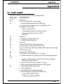
Table of Contents
Section 1 Introduction
Components Checklist ................................... 1-1
Overview
Power-On/Off (Remote) ................................. 1-2
System Block Diagram ................................... 1-3
Section 2 Features
EP-MVP4G Features..................................... 2-1
Section 3 Installation
EP-MVP4G Detailed Layout ......................... 3-2
Easy Installation Procedure
Configure Jumpers......................................... 3-3
System Memory Configuration ...................... 3-5
Device Connectors ........................................ 3-8
External Modem Ring-in Power ON and
Keyboard Power ON Function (KBPO)........ 3-10
Section 4 Award BIOS Setup
BIOS Instructions .......................................... 4-1
Standard CMOS Setup .................................. 4-2
BIOS Features Setup ..................................... 4-3
Chipset Features Setup ................................... 4-8
Power Management Setup .............................. 4-11
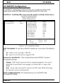
PNP/PCI Configuration .................................. 4-14
Load Setup Defaults ....................................... 4-16
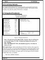
Integrated Peripherals ..................................... 4-16
Sensor And CPU Speed Setup ....................... 4-20
Change Supervisor or User Password ............. 4-21
IDE HDD Auto Detection............................... 4-22
Page

EP-MVP4G
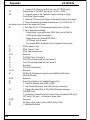
HDD Low Level Format ............................... 4-24
Save & Exit Setup .......................................... 4-24
Exit Without Saving......................................... 4-24
Appendix
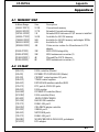
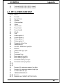
Appendix A
Memory Map................................................. A-1
I/O Map......................................................... A-1
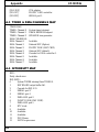
Timer & DMA Channels Map......................... A-2
Interrupt Map ................................................. A-2
RTC & CMOS RAM Map ............................ A-3
Appendix B
POST Codes ................................................. A-5
Unexpected Errors ......................................... A-8
Appendix C
Load Setup Defaults ...................................... A-9
Appendix D
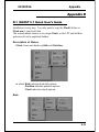
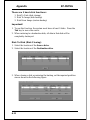
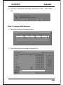
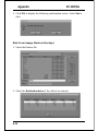
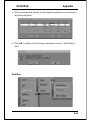
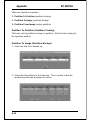
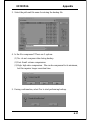
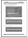
GHOST 5.1 Quick User’s Guide................... A-11

EP-MVP4G
Page Left Blank

IntroductionEP-MVP4G
Page 1-1
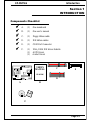
Section 1
INTRODUCTION
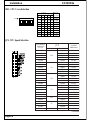
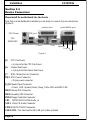
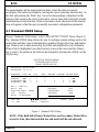
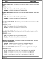
Components Checklist
üü
üü
ü A. (1) One mainboard
üü
üü
ü B. (1) One user’s manual
üü
üü
ü C. (1) Floppy ribbon cable
üü
üü
ü D. (1) IDE ribbon cables
üü
üü
ü E. (1) COM Port Connector
üü
üü
ü F. (1) Ultra_DMA IDE driver diskette
(1) AGP Drivers
(1) Audio Drivers
USER’S
MANUAL
EP-MVP4G
B
A
C
D
F
or
E
FDD1
J2
1
5
1
5
JP1
1
SOCKET 7
1

Introduction EP-MVP4G
Page 1-2
ATX
POWER SUPPLY
EP-MVP4G Board
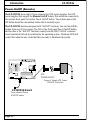
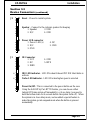
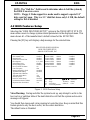
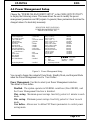
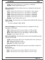
Power-On/Off (Remote)
The EP-MVP4G has a single 20-pin connector for ATX power supplies. For ATX
power supplies that support the Remote On/Off feature, this should be connected to
the systems front panel for system Power On/Off button. The systems power On/
Off button should be a momentary button that is normally open.
The EP-MVP4G has been designed with “Soft Off" functions. You can turn Off the
system from one of two sources: The first is the front panel Power On/Off button,
and the other is the "Soft Off" function (coming from the NMC-5V4AX’s onboard
circuit controller) that can be controlled by the operating system. Windows 95/98 will
control this when the user clicks that they are ready to Shutdown the system.
Case (chassis) Power
ON/OFF button
Figure 4: Simple ATX Power
ON/OFF Controller
J3
FDD1
J2
1
5
1
5
JP1
1
SOCKET 7
1

IntroductionEP-MVP4G
Page 1-3
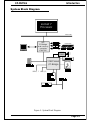
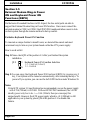
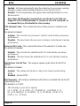
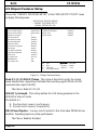
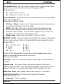
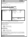
Figure 5: System Block Diagram
System Block Diagram
PAC
PCI Bridge
and memory
controller
VT82C501
VT82C686A
I/O Bridge
socket 7
Processor
100/66 MHz
100/66 MHz
USB 0, 1 USB 2, 3
AC97
CODEC
~
~
~
CRT

Introduction EP-MVP4G
Page 1-4
Page Left Blank

FeaturesEP-MVP4G
Page 2-1
Section 2
FEATURES
EP-MVP4G Features:
• Intel Pentium
®
Processor, Pentium Processor with MMX technology, AMD
K5/K6, Cyrix 6x86L/6x86MX & idt C6 operating at 133 ~ 450 MHz with
321 ZIF socket 7 provides scalability to accept faster Processors in the
future.
• Designed with VIA MVP4 AGPset.
• Supports up to 768 Mega of DRAM (minimum of 16 MB) on board, You can
use 168-pin DIMM x 3. It will automatically detect Extended Data Output
(EDO) DRAM at 66MHz only or Synchronous DRAM memory (SDRAM) at
66MHz or 100MHz (please see Section 3-2).
• Supports (1) 16 bit ISA slots, (4) 32 bit PCI slots, (1)AMR and provides
(2) independent high performance PCI IDE interfaces capable of supporting PIO
Mode 3/4 and Ultra DMA 33/66 devices. The EP-MVP4G supports (2) PCI
Bus Master slots and a jumperless PCI INT# control scheme which reduces
configuration confusion when plugging in PCI card(s).
• Supports ATAPI (e.g. CD-ROM) devices on both Primary and Secondary IDE
interfaces.
• Designed with lntegrated Multi I/O: (1) floppy port, (1) parallel port (EPP,
ECP), and (2) serial ports (16550 Fast UART).
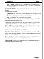
Note: Japanese “Floppy 3 mode” is also supported
• Features Award Plug & Play BIOS. With Flash Memory you can always
upgrade to the current BIOS as they are released.
• EP-MVP4G utilizes a Lithium battery which provides environmental protection
and longer battery life.
• Software power-down when using Windows
®
95/98.
• Supports ring-in feature (remote power-on through external modem,
allows system to be turned on remotely).

Features EP-MVP4G
Page 2-2
• Resume by Alarm - Allows your system to turn on at a preselected time.
• Supports CPU Hardware sleep and SMM (System Management Mode).
• Supports Keyboard power ON function (KBPO).
• Supports USDM software to offer motherboard various status.
• Supports the CPU and Chassis fan Auto stop in sleep mode.
• Built-in WOL (Wake On Lan) Connector.
• Built-in Sound Blaster/DirectSound AC97 Audio.
• Built-in AGP 2D/3D Graphics Accelerator.

InstallationEP-MVP4G
Page 3-1
Section 3
INSTALLATION

Installation EP-MVP4G
Page 3-2
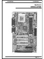
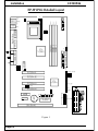
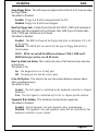
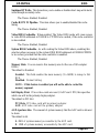
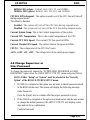
Figure 1
EP-MVP4G Detailed Layout
PCI Slot #2
PCI Slot #3
PCI Slot #4
AMR
Battery
VIA
VT8501
VIA
VT82C686A
COM 1
USB
VGA
Parallel Port
USB 1
(Top)
Mouse
(Top)
USB 0
(Bottom)
PS/2
Keyboard
(Bottom)
IDE1
Secondary IDE
FDD1
Flash Memory
for BIOS
J7:WOL
Game Port
SOCKET 7
JP4
1
DIMM 3
Bank 2
DIMM 2
Bank 1
DIMM 1
Bank 0
CPU FAN
J4
ISA Slot #1
PCI Slot #1
JP3
POWER_ON/OFF
SPK
Power LED
RESET
J2
1
J3
IR CONN.
5
1
5
Chassis FAN
J6
JP1
1
COM2
USB CONN.
CD1
AUX1
ON
IDE2

InstallationEP-MVP4G
Page 3-3
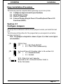
Easy Installation Procedure
The following must be completed before powering on your new system:
3-1. Configure Jumpers to match your hardware
3-2. Install memory chips
3-3. Device Connectors
3-4. External Modem Ring-in Power ON and Keyboard Power ON
Functions (KBPO)
Section 3-1
Configure Jumpers
We design this motherboard with the fewest jumpers to make your install fast and
easy.
The following will describe all of the jumpers that you are required to set before
moving on to step 3-2.
Note: The jumpers as depicted as shown (Figure 1) in their correct physi-
cal orientation.
JP4 Keyboard Power-ON function (refer to the section 3-4)
JP4 = 1-2 -
= 2-3 -
Disabled(Default)
Enabled
1
3
J7 WOL (Wake On Lan) Connector
Reserved for NIC (Network Interface Card) to
Wake the System.
JP1 = 1-2 - Run Mode (Default)
= 2-3 - Clear CMOS (momentarily)
JP1 CMOS Clear
1
3

Installation EP-MVP4G
Page 3-4
1
2
34
SW 1 CPU
Vcore
2
3
4
5
ON
ON
ON
ON
ON
ON
1.8V
2.0V
2.1V
ON
ON
ONON
ON
2.2V
2.3V
2.4V
3.2V
2.9V
2.8V
5
1
ON
ON
ON
ONON
ON
ON
SW1: CPU Vcore Selection
JP3: CPU Speed Selection
XMM/muitneP
6K/5KDMA
6C-TDI
3PJ
MBI/xiryC
IIM/XM68x6
reilpitluMkcolCsuB
zHM661
X5.2
zHM66002RP
zHM57332RP
zHM38662RP
zHM59003RP
zHM052zHM001663RP
ZHM002
X3
zHM66662RP
zHM57003RP
zHM052zHM38333RP
zHM59004RP*
zHM003zHM001334RP*
zHM332
X5.3
zHM66003RP
zHM57333RP
zHM38004RP*
zHM333zHM59664RP*
zHM053zHM001005RP*
zHM662
X4
zHM66333RP
zHM57004RP
zHM333zHM38664RP*
zHM083zHM59335RP*
zHM004zHM001055RP*
zHM003
X5.4
zHM66
zHM054zHM001
zHM333
X5
zHM66
zHM574zHM59
zHM005zHM001
zHM663X5.5zHM66
* Reserved

InstallationEP-MVP4G
Page 3-5
Section 3-2
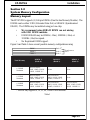
System Memory Configuration
Memory Layout
The EP-MVP4G supports (3) 168-pin DIMMs (Dual In-line Memory Module). The
DIMMs can be either EDO (Extended Data Out) or SDRAM (Synchronized
DRAM). The DIMMs may be installed using just one chip.
• We recommend using SDRAM DIMM can not mixing
with EDO DIMM modules.
• DIMM SDRAM may be 83MHz (-12ns), 100MHz (-10ns) or
125MHz (-8ns) bus speed.
• No Registered DIMM support.
Figure 2 and Table 1 show several possible memory configurations using
* SDRAM only supports 8, 16, 32, 64, 128MB DIMM modules.
Table 1
DIMM 1
DIMM 2
Bank 0
Bank 1
-Synchronous
-EDO
DIMM 3
Bank 2
yromeMlatoT
1MMID
)0knaB(
2MMID
)1knaB(
3MMID
)2knaB(
BM821=
mumixaM
*MARDS/ODE
,BM23,BM61,BM8
1XBM821,BM46
enoNenoN
BM652=
mumixaM
*MARDS/ODE
,BM23,BM61,BM8
1XBM821,BM46
*MARDS/ODE
,BM23,BM61,BM8
1XBM821,BM46
enoN
BM483=
mumixaM
*MARDS/ODE
,BM23,BM61,BM8
1XBM821,BM46
*MARDS/ODE
,BM23,BM61,BM8
1XBM821,BM46
*MARDS/ODE
,BM23,BM61,BM8
1XBM821,BM46

Installation EP-MVP4G
Page 3-6
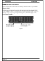
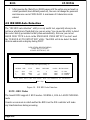
DIMM Module Installation
Figure 3 displays the notch marks and what they should look like on your DIMM
memory module.
DIMMs have 168-pins and two notches that will match with the onboard DIMM
socket. DIMM modules are installed by placing the chip firmly into the socket at a
90 degree angle and pressing straight down (figure 6) until it fits tightly into the
DIMM socket (figure 7).
Figure 3
CENTER KEY ZONE
(3.3 V DRAM)
LEFT KEY ZONE
(UNBUFFERED)

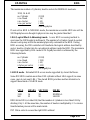
InstallationEP-MVP4G
Page 3-7
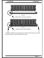
Figure 4
DIMM Module clip before installation
Figure 5
DIMM Module clip after installation
To remove the DIMM module simply press down both of the white clips on either
side and the module will be released from the socket.

Installation EP-MVP4G
Page 3-8
Section 3-3
Device Connectors
Please install the motherboard into the chassis.
Now that your motherboard is installed you are ready to connect all your connections
(figure 6).
J4: CPU Fan Power
• A plug-in for the CPU Fan Power
J6: Chassis Fan Power
• A plug-in for the chassis Fan Power
J7: WOL (Wake On Lan) Connector
PW1: ATX Power Connector
• 20-pin power connector
J2,J3:Chassis Panel Connector
• Power_LED, Speaker, Reset, Sleep, Turbo LED and HDD LED
IDE1:Primary IDE Connector
IDE2:Secondary IDE Connector
FDD1:Floppy Controller Connector
CD1: MITSUMI CD-ROM Audio_in
AUX1: Extra CD Audio Connector
COM2: RS232 COM2 Commector
USB CONN.: The third and fourth USB port (cable optional)
PS/2 Mouse
PS/2
KEYBOARD
COM1 VGA1
parallel port
Speaker
Joystick/Midi port
USB port
Line_in
MIC
Figure 6
La pagina si sta caricando...
La pagina si sta caricando...
La pagina si sta caricando...
La pagina si sta caricando...
La pagina si sta caricando...
La pagina si sta caricando...
La pagina si sta caricando...
La pagina si sta caricando...
La pagina si sta caricando...
La pagina si sta caricando...
La pagina si sta caricando...
La pagina si sta caricando...
La pagina si sta caricando...
La pagina si sta caricando...
La pagina si sta caricando...
La pagina si sta caricando...
La pagina si sta caricando...
La pagina si sta caricando...
La pagina si sta caricando...
La pagina si sta caricando...
La pagina si sta caricando...
La pagina si sta caricando...
La pagina si sta caricando...
La pagina si sta caricando...
La pagina si sta caricando...
La pagina si sta caricando...
La pagina si sta caricando...
La pagina si sta caricando...
La pagina si sta caricando...
La pagina si sta caricando...
La pagina si sta caricando...
La pagina si sta caricando...
La pagina si sta caricando...
La pagina si sta caricando...
La pagina si sta caricando...
La pagina si sta caricando...
La pagina si sta caricando...
La pagina si sta caricando...
La pagina si sta caricando...
La pagina si sta caricando...
La pagina si sta caricando...
La pagina si sta caricando...
La pagina si sta caricando...
La pagina si sta caricando...
La pagina si sta caricando...
-
 1
1
-
 2
2
-
 3
3
-
 4
4
-
 5
5
-
 6
6
-
 7
7
-
 8
8
-
 9
9
-
 10
10
-
 11
11
-
 12
12
-
 13
13
-
 14
14
-
 15
15
-
 16
16
-
 17
17
-
 18
18
-
 19
19
-
 20
20
-
 21
21
-
 22
22
-
 23
23
-
 24
24
-
 25
25
-
 26
26
-
 27
27
-
 28
28
-
 29
29
-
 30
30
-
 31
31
-
 32
32
-
 33
33
-
 34
34
-
 35
35
-
 36
36
-
 37
37
-
 38
38
-
 39
39
-
 40
40
-
 41
41
-
 42
42
-
 43
43
-
 44
44
-
 45
45
-
 46
46
-
 47
47
-
 48
48
-
 49
49
-
 50
50
-
 51
51
-
 52
52
-
 53
53
-
 54
54
-
 55
55
-
 56
56
-
 57
57
-
 58
58
-
 59
59
-
 60
60
-
 61
61
-
 62
62
-
 63
63
-
 64
64
-
 65
65


EPOX EP-MVP4G Manuale utente
- Categoria
- Schede madri
- Tipo
- Manuale utente
- Questo manuale è adatto anche per
in altre lingue
- English: EPOX EP-MVP4G User manual