High One MPG 75 A Manuale del proprietario
- Tipo
- Manuale del proprietario

Table de cuisson
Piano di cottura
Tip. Montagnani - Italy - Cod. 535170 0204
FR
Notice d’emploi et d’installation
Hob
Use and installation instructions
IT
Istruzioni per l’uso e l’installazione
GB


3
Per la Vostra Sicurezza
Queste avvertenze sono state redatte per la Vostra sicurezza e per quella degli altri.
Vi preghiamo dunque di leggerle attentamente prima di installare e di utilizzare
l’apparecchiatura. Conservate questo libretto di istruzioni per qualsiasi futura consul-
tazione. Nel caso che l’apparecchiatura venga venduta o trasferita, assicurateVi che
il libretto venga consegnato al nuovo utilizzatore.
Installazione
• L’installazione dell’apparecchiatura ed il collegamento alla rete elettrica devono
essere eseguiti solamente da PERSONALE QUALIFICATO. Prima di qualsiasi
intervento, è necessario verificare che l’apparecchiatura sia DISINSERITA dalla rete
elettrica.
• E’ rischioso modificare o tentare di modificare le caratteristiche di questo prodotto.
• Dopo aver tolto l’apparecchiatura dall’imballaggio, assicurateVi che il prodotto non
risulti danneggiato e che il cavo di alimentazione elettrica sia in perfette condizioni.
In caso contrario, rivolgeteVi al rivenditore prima di mettere in funzione l’apparec-
chiatura.
• La Casa costruttrice declina ogni responsabilità nel caso le norme antinfortunistiche
non vengano rispettate.
• AssicurateVi che l'aria possa circolare liberamente attorno all'apparecchiatura. Una
scarsa venti lazione produce carenza di ossigeno.
• AssicurateVi che l'apparecchiatura sia alimentata con il tipo di gas indicato sull'apposita
etichetta adesiva, posta nelle immediate vicinanze del tubo di allacciamento alla
rete del gas.
• L'utilizzo di un apparecchio di cottura a gas produce calore e umidità nel
locale in cui è installato. Assicurate una buona aerazione del locale, mantenendo
aperte ed effi cienti le prese d'aria o installando una cappa di aspirazione con
condotto di scarico.
• Se utilizzate l'apparecchiatura intensamente e per un tempo prolungato, dovete
rendere più efficace l'aerazione, per esempio aprendo una finestra o aumentando
la potenza dell'aspiratore elettrico, se presente.
Durante l'uso
• Questo prodotto è stato realizzato per cuocere cibi, all'interno di abitazioni comuni
a scopo non professionale. Evitate di usarlo per qualsiasi altro scopo.
• Dopo aver utilizzato l’apparecchiatura, assicurateVi che tutti i comandi siano in
posizione “CHIUSO” o “SPENTO”.
• Se usate una presa di corrente nelle vicinanze di questa apparecchiatura, fate
attenzione che i cavi degli elettrodomestici che state usando non la tocchino e siano
sufficientemente lontani dalle parti calde di questa apparecchiatura.
IT

4 45
Sicurezza dei bambini
• Questa apparecchiatura deve essere adoperata solo da persone adulte. AssicurateVi
che i bambini non tocchino i comandi o non giochino con l’apparecchiatura.
• Le parti esposte di questa apparecchiatura si riscaldano durante la cottura e
rimangono calde per un certo tempo anche dopo lo spegnimento. Tenete lontani i
bambini fino a quando l’apparecchiatura non si è raffreddata.
Pulizia e manutenzione
• Tenete ben pulita l’apparecchiatura. I residui di cibo possono causare rischi di
incendio.
Assistenza e ricambi
• In caso di guasti, non cercate mai di riparare l’apparecchiatura di persona. Le
riparazioni effettuate da persone non competenti possono causare danni e incidenti.
Per prima cosa, consultate il contenuto di questo libretto. Se non trovate le informazioni
che Vi interessano, contattate il Centro di Assistenza più vicino. L’assistenza a questa
apparecchiatura deve essere effettuata da un Centro di Assistenza Tecnica autorizzato.
Richiedete sempre l’impiego di ricambi orginali.
Consigli per la protezione dell'ambiente
• Tutti i materiali utilizzati sono compatibili con l’ambiente e riciclabili. Vi preghiamo
di dare il Vostro contributo alla conservazione dell’ambiente, utilizzando gli appositi
canali di raccolta differenziata.
Apparecchiature in disuso
• Gli apparecchi dismessi o non più utilizzabili non sono rifiuti senza valore. Attraverso
lo smaltimento ecologico, diversi materiali impiegati nella produzione della Vostra
apparecchiatura possono essere recuperati.
• InformateVi sulla attuali possibilità di smaltimento presso il Vostro rivenditore
specializzato, oppure presso la Vostra Amministrazione Comunale.
• Prima di rottamare l’apparecchiatura, tagliate il cavo di alimentazione e
rendetela inservibile.
Queste istruzioni sono valide solamente per i paesi di destinazionei cui
simboli di identificazione figurano sulla copertina del libretto istruzioni e
sull’apparecchio
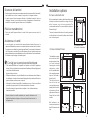
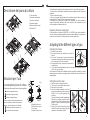
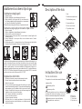
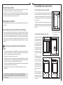
Installation options
On base cabinet with door
When constructing the cabinet, suitable precautions must
be taken to prevent contact with the casing of the hob,
which becomes very hot during operation.The
recommended method for overcoming this problem is
illustrated in fig. 1.
The panel underneath the hob must be easily removable
to allow the hob to be locked in position and released in
case of servicing work.
On base cabinet with oven
The installation compart-
ment must have the di-
mensions shown in figu-
res 2 and 3 and must
have supports to allow
satisfactory ventila-
tion.Two possible metho-
ds for avoiding overhea-
ting are illustrated in
figures 4 and 5.
The electrical connec-
tions of the hob and
oven must be made se-
parately both for electri-
cal reasons and to sim-
plify removal of the oven
through the front of the
cabinet.
Wall cabinets or ex-
tractor hoods must be at
least 650 mm above the
hob.
a Removable panel
b) Space for connections
60
b
a
30
20
min
Fig. 1
Fig. 5
120cm
180 cm
2
2
Fig. 4
50 cm
360 cm
2
2
Fig. 2
560 min
550 min
Fig. 3
480
591
380
140
30
IT GB

44 5
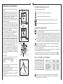
Insertion and fixing
Before inserting the hob in the installation
opening, place the special gasket around the
bottom edge of the hob.
It is important to fix this gasket evenly, without
gaps or overlapping, to prevent liquid from
seeping underneath the hob.
1) Remove the pan stands and the burner
caps and turn the hob upside down, taking
care not to damage the ignition plugs and
the thermocouples.
2) Place the gasket around the bottom edge
of the hob as shown in the illustration on the
right.
3) Place the hob in the installation opening
and push it down so that the hob is resting
firmly on the cabinet, as shown in the
illustration.The side springs will hold it in
place.
A) gasket
Building into fitted kitchen units
These hobs are designed for installation in fitted kitchen units up to 600 mm deep with
suitable characteristics.
Any cabinet side panels taller than the height of the hob itself must be at least 150
mm away from the opening into which the hob is inserted.
The dimensions of the hob and the installation opening are shown in the illustration.
480
560
70
680
510
50
600
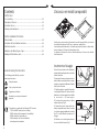
Sommario
Per l’Utente
Per la Vostra Sicurezza............................................................2
Descrizione del piano di cottura...............................................5
Istruzioni per l’uso....................................................................5
Pulizia e manutenzione............................................................7
Per l’Installatore
Caratteristiche tecniche............................................................9
Istruzioni per l’installatore.......................................................10
Collegamento elettrico ...........................................................12
Adattamento ai diversi tipi di gas ...........................................13
L’incasso nei mobili componibili..............................................14
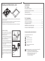
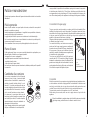
Guida alla lettura delle istruzioni
I seguenti simboli Vi aiuteranno nella
lettura delle istruzioni:
Informazioni di sicurezza
Istruzioni “Passo a passo”
Suggerimenti e Consigli
Informazioni legate alla protezione
dell’ambiente
Questa apparecchiatura è conforme alle seguenti Direttive CEE:
- 73/23 e 90/683 (relative alla Bassa Tensione);
- 89/336 (relativa alla Compatibilità Elettromagnetica);
- 90/396 (relativa alla Apparecchiature a Gas)
- 93/68 (relativa alle Norme Generali)
e successive modificazioni.
a
ITGB

Le manopole del piano di cottura
I simboli posti sulle manopole hanno il seguente significato:
nessuna erogazione di gas
massima erogazione di gas
minima erogazione di gas
Tutte le posizione di funzionamento devono
essere scelte tra le posizioni di massimo e
minimo, mai tra il massimo e la chiusura.
(simbolo presente per versione con
accensione sulla manopola.)
6 43
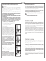
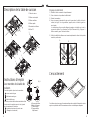
Descrizione del piano di cottura
1.Piano di cottura
2.Bruciatore semi-rapido
3.Bruciatore ausiliario
4.Bruciatore rapido
5.Manopole dei bruciatori
6.Bruciatore T.C.
2
5
3
6
2
4
1
Istruzioni per l’uso
B
A
C
A
B
C
D
Fig. 1
A-Cappello del bruciatore
B-Candeletta di accensione
C- Termocoppia
D-Cappello del tripla corona
3
4
2
1
2
5
3
2
6
1
5
6
5
2
1
Setting the minimum level
1) Light the burner as already described.
2) Turn the tap to the minimum flame position.
3) Remove the control knobs.
4) Use a thin straight screwdriver to turn the
by-pass pin located next to the tap rod (see
fig. B).For LPG, turn the by-pass pin fully
clockwise.
The result should be a small, homogeneous
flame which is uniform around the entire
burner ring.For the Dual Triple Flame version
see fig. A, by-pass 1 central burner, by-pass
2 both burners.
5) Finally, check that the burner does not go
out when the tap is turned quickly from the
maximum to the minimum position.
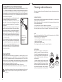
If the lead has to be replaced, only HO5RR-F or HO5RN-F type cables suitable for
the load and the operating temperature must be used.In addition, the yellow/green
earth wire must be about 2 cm longer than the live and neutral wires.
Replacing the power supply lead
B
The flexible mains lead, plug and socket must not be in contact with hot surfaces.
The lead must not be trapped or pulled taut when the appliance is fitted. Plug in the
appliance.
Turn on the electricity supply.
In all cases, the power supply lead must be positioned so that it does not reach a
temperature 50°C above the room temperature in any point.
One example of an ideal route is shown in the illustration.The cable is guided by
means of band clamps fixed to the side of the cabinet, in order to avoid any contact
with the appliance underneath the hob.
A
Changing the nozzles
1) Remove the pan stands
2) Remove the burner caps and flame caps from the
burners.
3) Use a size 7 socket wrench to unscrew and remove
the nozzles, replacing them with those corresponding
to the type of gas to be used (see table).
4) Reassemble the parts, reversing the operations de-
scribed above.
5) Then replace the setting data plate (close to the mains gas connection) with the
one for the new type of gas
If the pressure of the gas used is different from that specified (or variable), a suitable
piped gas pressure regulator complying with the standard must be installed on the
supply pipeline.
Adapting to the different types of gas
1
2
IT GB

42 7
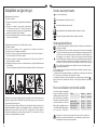
Per un corretto uso del piano
Per un minor consumo di gas ed
un migliore rendimento, usate so-
lamente recipienti a fondo piatto
e di dimensioni adatte ai fornelli,
come evidenziato nella tabella a
lato. Inoltre, non appena un liquido
inizia a bollire, fate attenzione a
ridurre la fiamma quanto basta
per mantenere l'ebollizione.
Bruciatore diametro diametro
minimo massimo
Grande (rapido) 180 mm. 220 mm.
Medio (semirapido) 120 mm. 200 mm.
Piccolo (Ausiliario) 80 mm. 160 mm.
Tripla Corona 220 mm. 260 mm.
Durante le cotture in cui vengono impiegati grassi od olii, sorvegliate
attentamente le Vostre pietanze, perché queste sostanze, portate ad alte
temperature, possono incendiarsi.
Accensione dei fornelli
Per ottenere più facilmente la fiamma, accendete il fornello prima di mettere
un recipiente sulla griglia.
Per accendere un fornello, procedete come segue:per versione con accensione
sulla manopola, spingete a fondo la manopola corrispondente al fornello e
ruotatela in senso antiorario fino al simbolo di "massima erogazione",oppure
premere sul pulsante sè l'apparecchio è dotato di singola accensione
Dopo aver acceso la fiamma, tenete premuta la manopola per circa 10 secondi;
questo tempo è necessario per riscaldare la "termocoppia" (Fig.1-C) e attivare
la valvola di sicurezza, che altrimenti fermerebbe l'erogazione del gas.
Quindi, controllate che la fiamma sia regolare e ruotate la manopola fino ad
ottenere l'intensità desiderata.
In caso di mancanza di energia elettrica, avvicinate una fiamma al bruciatore e
procedete come già descritto.
Se dopo alcuni tentativi la fiamma non si accende, controllate che il "cappellotto" e
la "corona spartifiamma" siano nella corretta posizione.
Per spegnere la fiamma, ruotate la manopola in senso orario fino al simbolo .
Prima di togliere i recipienti dai fornelli, abbassate sempre la fiamma o spegnetela.
Versione dual tripla corona
nessuna erogazione di gas
massima erogazione di gas bruciatore centrale
minima erogazione di gas bruciatore centrale
massima erogazione di gas simultanea bruciatore esterno e centrale
minima erogazione di gas simultanea bruciatore esterno e centrale
Electrical connection
WARNING: THIS APPLIANCE MUST BE EAR-
THED.
All external wiring must comply with the IEE
Regulations for the Electrical Equipment of
Buildings. The electrical supply can be by either
a plug and socket or a permanently wired
connection via a double - pole switch.
Should the plug (where supplied) not fit the socket
in your home, it should be removed and replaced
with a suitable plug.
Note: If a moulded plug is fitted which is not
suitable, it must be cut off and disposed of properly.
To avoid the risk of electrocution, the moulded
plug must not be left where children might find it
and plug it into a supply socket. It must not be
used for any other appliance.
Three pin plugs to BS1363 with a capacity of not
less than 13A must be used and fitted with a 3
amp fuse ‘ASTA’ approved to BS 1362.
With moulded plugs, after replacing the fuse the
cover must be refitted. If the cover is lost, the
plug must not be used until a replacement cover
has been obtained from your supplier. The colour
of the correct fuse cover is that of the coloured
insert in the base of the fuse recess, or stated
elsewhere on the plug. Always state this colour
when ordering a replacement fuse cover.
If you wish to make a direct connection to the
mains, an omnipolar switch with a gap between
the contacts of at least 3 mm, of suitable rating
for the load and complying with the regulations in
force, must be installed between the appliance
and the mains.
IMPORTANT
The wires in the mains lead are coloured in
accordance with the following code:-
GREEN AND YELLOW EARTH
BLUE NEUTRAL
BROWN LIVE
The wires should be connected into the terminal
of your plug as follows:
EARTH: to the terminal marked E, or coloured
GREEN or GREEN / YELLOW.
NEUTRAL: to the terminal marked N, or coloured
BLACK or BLUE.
LIVE: to the terminal marked L, or coloured RED
or BROWN.
When wiring the plug ensure that all strands of wire are retained in each terminal.
SÍ
TUBO RÍGIDO DE
COBRE O FLEXIBLE DE
ACERO INOX
Abertura de
servicio
realizada
en el
mueble
VISTA DE ATRÁS
NO
VISTA DE ATRÁS
TIRAS
green and yellow
(earth)
blue (neutral)
brown (live)
fuse
(3amp)
3A
live
Neutral
Earth (Yellow/Green)
BLU
ITGB

8 41
Prima di ogni operazione disinserite l’apparecchiatura dalla rete elettrica e lasciatela
raffreddare.
Pulizia generale
Lavate le parti smaltate con acqua tiepida e detersivo, evitando di usare prodotti
abrasivi che potrebbero rovinarle.
Lavate frequentemente gli spartifiamma e i cappellotti con acqua bollente e detersivo,
avendo cura di togliere ogni incrostazione.
Le griglie del piano di lavoro possono essere lavate anche nella lavastoviglie.
Per le macchie persistenti usare i normali detersivi non abrasivi o prodotti specifici,
comunemente reperibili in commercio.
Vi raccomandiamo di non usare per la pulizia pagliette, lane di acciaio o acidi.
Piano di lavoro
Pulite regolarmente il piano con un panno morbido imbevuto di acqua tiepida e poco
detersivo liquido. Evitate di usare i seguenti prodotti:
- detergenti per la casa o candeggianti;
- pagliette saponate non adatte a recipienti anti-aderenti;
- pagliette in lana di acciaio;
- smacchiatori per il bagno o lavabi.
Nel caso il piano dovesse sporcarsi notevolmente, utilizzate prodotti specifici reperibili
in commercio.
Candeletta di accensione
L'accensione automatica dei fornelli,quando
l'apparecchio ne è dotato, è assicurata dalla
presenza di una "candeletta" in ceramica ed un
elettrodo in metallo (indicati nella fig. 1 con la
lettera B). Procedete periodicamente ad una
accurata pulizia di queste parti del piano. Inoltre,
per evitare difficoltà di accensione, controllate
che le cave del bruciatore non siano otturate.
Per rimuovere le incrostazioni dalle cave del
bruciatore, togliete il cappello e separate le due
parti (vedi figura a fianco). Terminata la pulizia,
rimontate insieme le due parti e rimettetele cor-
rettamente nella loro posizione.
Dopo il lavaggio, rimettete al loro posto le griglie
del piano controllandone la corretta posizione.
Pulizia e manutenzione
Connection to the gas supply
The gas connection must be made in accordance with the local standards.When
installing fit a safety tap at the end of the pipeline.The appliance leaves the factory
tested and set for the type of gas indicated on the plate inside the bottom guard, close
to the gas connection pipe.Make sure that the type of gas to be supplied to the
appliance is the same as that shown on the plate.
Otherwise, follow the instructions provided in the "Adapting
to different types of gas" section.
For maximum efficiency and minimum consumption,
make sure that the gas supply pressure complies with
the values shown in the table of "Burner characteristics".
If the pressure of the gas used is different from that
specified (or variable), a suitable pressure regulator must
be installed on the supply pipeline.
The union must be fitted on the end of the gas train,
complete with GJ 1/2" threaded nut, fitting the gasket
between the components as shown in the illustration.The
gaskets must comply with the local standards.Screw the
parts together without forcing, fit the union so that it points
in the direction required then tighten all parts.
Connection
Make the connection to the gas system using a rigid metal pipe and regulation unions,
or with a stainless steel hose complying with the local standardì .If metal hoses are
used, take care that they do not come into contact with mobile parts and are not
crushed.This must also be checked if the hob is to be combined with an oven.
The gas intake connection of the appliance has a 1/2" male thread.
When making the connection, take care not to apply stresses of any kind to the
appliance.
When the installation is complete, always check that all the unions are absolutely
tight using a soapy solution.Never use a flame to make this check.
A) End of gas train with
nut
B) Gasket
C) Adjustable union
A
B
C
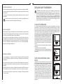
room, provided it is possible for the ventilation opening to be increased in proportion
to the delivery rate of the fan (fig. C).For a kitchen, the delivery rate of this electric fan
must guarantee an hourly air exchange of 3-5 times its volume.In both instances, the
use of flues already used by other appliances to discharge the flue gases is forbidden.
IT GB

40 9
Fate controllare periodicamente lo stato di conservazione e di efficacia del tubo del
gas, e se presente, del regolatore di pressione. Qualora venissero riscontrate anomalie,
non richiedete riparazioni, ma fate sostituire la parte difettosa.
A garanzia del buon funzionamento e della sicurezza, è necessario procedere
periodicamente all’ingrassaggio dei rubinetti di regolazione del gas.
La lubrificazione periodica dei rubinetti deve essere eseguita solamente da
personale qualificato al quale ci si deve rivolgere anche nel caso si riscontrassero
anomalie nel funzionamento dell’apparecchiatura.
Manutenzione periodica
Questa apparecchiatura, prima di lasciare la fabbrica, è stata collaudata e messa a
punto da personale esperto e specializzato, in modo da dare i migliori risultati di
funzionamento. Ogni riparazione o messa a punto che si rendesse in seguito necessaria,
deve essere fatta con la massima cura e attenzione.
Per questo motivo raccomandiamo di rivolgerVi sempre al Concessionario che ha
effettuato la vendita o al nostro Centro di Assistenza più vicino, specificando il tipo di
inconveniente, il modello dell'apparecchiatura (Mod.), il numero di prodotto (Prod.
No.) ed il numero di fabbricazione (Ser. No.). Questi dati sono riportati nella targhetta
collocata sulla prima pagina di copertina. Richiedete sempre l’impiego di ricambi
originali.
Assistenza e ricambi
Condizioni di garanzia
La Sua nuova apparecchiatura è coperta da garanzia. Le condizioni di garanzia sono
riportate per esteso nell'opuscolo "Norme di garanzia - Centri assistenza" che trovate
all'interno dell'apparecchiatura.
Conservi con cura, insieme all'opuscolo, la ricevuta o lo scontrino fiscale, oppure
ancora la bolla di accompagnamento, che servono a documentare l'acquisto della
Sua apparecchiatura e la data in cui é avvenuto.
In caso di intervento del Servizio di Assistenza, esibite questi documenti al personale
incaricato. Senza il rispetto di questa procedura, il Servizio di Assistenza sarà costretto
ad addebitare qualsiasi eventuale riparazione.
In caso di necessità, potrà cercare il Centro più vicino consultando l'opuscolo "Norme
di garanzia - Centri assistenza" oppure le Pagine Gialle nella rubrica Elettrodomesti-
ci/Riparazione.
Instructions for the installation technician
Provision for ventilation
The room containing the appliance should have an air
supply in accordance with B.S.5440 Part 2: 1989. All
rooms require an openable window or equivalent, while
some rooms require a permanent vent in addition to the
openable window. The appliance should not be installed
in a bedsitting room with volume less than 20m
3
. If it is
installed in a room of volume less than 5m
3
an air vent
of effective area 100cm
2
is required; if it is installed in a
room of volume between 5m
3
and 10m
3
, an air vent of
effective area 50cm
2
is required; while if the volume
exceeds 11m
3
, no air vent is required. However, if the
room has a door that opens directly to the outside, no air
vent is required even when the room volume is between
5m
3
and 10m
3
.
If there are other fuel burning appliances in the same
room, B.S.5440 Part 2 : 1989 should be consulted to
determine the requisite air vent requirements.
Location of appliance
The appliance may be installed in a kitchen/kitchen diner
but NOT in a room containing a bath or shower.
Discharge of flue gases
Gas cooking appliances must discharge their flue gases
through hoods connected directly to flues or the outdoors.If
it is not possible to install the hood (fig. B) an electric fan
must be installed on the outside wall or the window of the
CAUTION:
Before any procedure, it is important to check that the appliance is DISCONNECTED
from the electrical mains.The Manufacturer declines all responsibility for any damage
deriving from installation in breach of the regulations in force or from failure to comply
with the accident prevention regulations.
This appliance shall be installed in accordance with the regulations in force and only
in a well-ventilated space. Read the instructions before installing or using this appliance.
In the UK the regulations and standards are as follows:-
In your own interest and that of safety, it is law that all gas appliances must be installed
by competent persons.
CORGI registered installers undertake to work to safe and satisfactory standards.
Failure to install the appliance correctly could invalidate any warranty or liability claims
and lead to prosecution. The appliance must be installed in accordance with All relevant
British Standards / Codes of Practice, in particular BS 5440 Part 2 1989 and:-
• For Natural Gas - BS 6172 : 1990 and BS 6891 : 1988
• The Gas Safety (Installation and Use) regulations 1994.
• The relevant Building / IEE regulations
AIR INLET
Ø MIN. 100 cm
2
Fig. A
elettroventilatore
Fig. C
AIR INLET
Ø min. 100 cm
2
MINIMO 180 cm
Fig. B
AIR INLET
Ø MIN. 100 cm
2
MINIMO 180 cm
Ø
MIN. 100 cm
2
ITGB

10 39
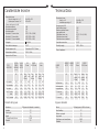
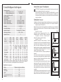
Caratteristiche tecniche
Bruciatore Ø By-pass del rubinetto in centesimi
Ausiliario 27
Semi-rapido 29
Rapido 39
T. Corona Nucleo/Corona 25/63
Standard 65
Diametri del by-pass
Dimensioni in mm:
Piano di cottura H x L x P 90 x 680 x 510
Apertura per l’incasso L x P 560 x 480
Potenza dei bruciatori in kW:
Bruciatore ausiliario 1,00
Bruciatore semi-rapido 1,65
Bruciatore rapido 3,0
Bruciatore T. Corona nucleo 0,70 (G 30 = 0,6 kW)
Bruciatore T. Corona totale 4,25 (G110 = 4 kW)
Bruciatore T. Corona standard 4,25 (G110 = 4 kW)
Categoria III 1a 2H3+
Raccordo di entrata gas G 1/2”
Taratura apparecchio Gas metano G20 - 20 mbar
Alimentazione elettrica 230 V ~ 50 Hz
Apparecchio di Classe : 3
PORTATA PORTATA G 20 G30/G31 G110
TIPO DI TERMICA TERMICA 20 mbar 28-30/37 mbar 8mbar
BRUCIATORE NOMINALE RIDOTTA
(p.c.s.)
kW kW Marc. Cons. Marc. Cons. Marc. Cons.
ugelli m
3
/h ugelli g/h ugelli m
3
/h
100/mm 100/mm 100/mm
Bruc. ausiliario 1,00 0,35 76 0,095 50 73 145 0,227
Bruc. semirapido 1,65 0,40 94 0,157 65 120 195 0,375
Bruc. rapido 3,00 0,65 128 0,286 85 219 274 0,682
Bruc. T.C. nucleo 0,70 0,20 63 0,067 37 51 120 0,159
totale 4,25 1,50 63+140 0,405 37+97 310 120+350 0,966
Bruc. T.C. standard 4,25 1,50 63+140 0,405 37+97 310 175+350 0,966
Technical Data
Burner Ø of tap by-pass in 100ths of a mm
Small auxiliary 27
Medium semi-rapid 29
Large rapid 39
Triple flame core burner/burner 25/63
Standard 65
By-pass diameters
MAXIMUM MINIMUM G 20 G30/G31
BURNER OUTPUT OUTPUT 20 mbar 28-30/37 mbar
TYPE
kW kW Nozzle Cons. Nozzle Cons.
marking m
3
/h marking g/h
100/mm 100/mm
Small aux burner 1,00 0,35 76 0,095 50 73
Medium semi-rapid b. 1,65 0,40 94 0,157 65 120
Large rapid burner 3,00 0,65 128 0,286 85 219
T.F. burner core 0,70 0,20 63 0,067 37 51
total 4,25 1,50 63+140 0,405 37+97 310
T.F. burner std 4,25 1,50 63+140 0,405 37+97 310
Dimensions in mm:
Hob H x L x P 90 x 680 x 510
Installation opening L x P 560 x 480
Burner power in kW:
Small auxiliary burner 1,00
Medium semi-rapid burner 1,65
Large rapid burner 3,0
Triple flame burner core 0,70 (G 30 = 0,6 kW)
Triple flame burner total 4,25
Triple flame burner standard 4,25
Gas intake connection G 1/2”
Electricity supply 230 V ~ 50 Hz
Class of appliance: 3
IT GB

38 11
Istruzioni per l’installatore
ATTENZIONE: Questo apparecchio può essere installato e funzionare solo in
locali permanentemente ventilati secondo UNI 7129 e UNI 7131.
L’installazione dell’apparecchiatura ed il collegamento alla rete elettrica devono
essere eseguiti solamente da PERSONALE QUALIFICATO. Prima di qualsiasi
intervento, è necessario verificare che l’apparecchiatura sia DISINSERITA dalla
rete elettrica. La società costruttrice declina ogni responsabilità per eventuali
danni derivanti da una installazione non conforme alle norme vigenti o da un
mancato rispetto delle norme antinfortunistiche.
Locale di installazione
Per il buon funzionamento dell’apparecchio a gas è indispensabile che nel locale
possa affluire, in modo naturale, l’aria necessaria alla combustione del gas. L’afflusso
di aria nel locale deve avvenire direttamente attraverso aperture praticate su pareti
esterne. Queste aperture devono avere una sezione libera di passaggio di almeno
100 cm
2
(fig.A). Si ricorda che la quantità d’aria necessaria alla combustione non deve
essere minore a 2m
3
/h per ogni kW di potenza (vedi potenza totale
in kW sulla targa matricola dell’apparecchio). Questa
apertura deve essere costruita in modo da non venire
ostruita sia dall’interno che dall’esterno e posizionata vicino
al pavimento, preferibilmente al lato opposto all’evacuazione
dei prodotti della combustione. Nel caso questa apertura
non sia fattibile nel locale dove è installata l’apparecchiatura,
l’aria necessaria può provenire da un locale adiacente,
purchè:
• questo locale non sia una camera da letto o un ambiente
pericoloso;
• questo locale non sia in depressione;
• la ventilazione fra il locale dove è installato l'apparecchio
ed il locale adiacente sia assicurata mediante aperture
permanenti.
Scarico dei prodotti della combu-
stione
Gli apparecchi di cottura a gas devono scaricare i prodotti
della combustione attraverso cappe collegate direttamente
a canne fumarie o direttamente all’esterno. In caso non
sia possibile installare la cappa (fig. B), è necessario
l’impiego di un elettroventilatore applicato alla parete
esterna o alla finestra dell’ambiente, purchè esistano le
condizioni affinchè l’apertura per la ventilazione possa
essere aumentata in proporzione alla portata dell’elettro-
ventilatore stesso (fig. C). Questo elettroventilatore deve
avere una portata tale da garantire, per un ambiente cucina,
un ricambio orario d’aria pari a 3 - 5 volte il suo volume.
In entrambi casi per lo scarico dei prodotti della comustione
è vietato servirsi di canne fumarie già utilizzate da altri
apparecchi.
ENTRATA ARIA
SEZIONE MIN. 100 cm
2
Fig. A
elettroventilatore
Fig. C
ENTRATA ARIA
SEZIONE MIN. 100 cm
2
MINIMO 180 cm
Fig. B
ENTRATA ARIA
SEZIONE MIN. 100 cm
2
MINIMO 180 cm
Ø
MIN. 100 cm
2
Have the condition and efficiency of the gas pipe and the pressure regulator (if installed)
checked periodically.If anomalies are found, do not request repairs but have the faulty
part replaced.
To ensure good performance and safety, the gas regulator taps must be greased
periodically.
Periodic lubrication of the taps must only be carried out by qualified staff, who
must also be contacted if the appliance malfunctions.
Routine maintenance
Before leaving the factory, this appliance was tested and adjusted by specialist skilled
staff to give the best operating results.Any subsequent necessary repairs or adjustments
must be carried out with the greatest care and attention.
For this reason, we strongly advise you always to contact the Dealer who sold you
the appliance or our nearest Service Centre, specifying the nature of the problem, the
model of the equipment (Mod.), the product number (Prod. No.) and the serial number
(Ser. No.).These data are provided in the plate on the cover of this manual.Always
request the use of original spare parts.
Service and parts
Warranty conditions
Your new appliance is covered by a warranty.The warranty conditions are provided
in full in the "Warranty conditions - Service centres" leaflet which you will find inside
the appliance.
Keep the fiscal receipt or delivery note, either of which documents your purchase of
the appliance and provides proof of date of purchase, in a safe place together with
the leaflet.
If the After-Sales Service is called in, show these documents to the staff.If this procedure
is not followed, the Service Centre will have no option but to charge for any repairs.
If necessary, you may find your nearest Centre by consulting the "Warranty conditions
- Service centres" .
ITGB

12 37
Collegamento alla alimentazione gas
Il collegamento gas deve essere eseguito in conformità con le norme UNI-CIG 7129
-7131. Prevedere nell’installazione un rubinetto di sicurezza all’estremità della tubazione.
L’apparecchiatura esce dalla fabbrica collaudata e regolata per il tipo di gas indicato
nella targhetta che si trova nella protezione inferiore, vicino al tubo di collegamento
gas. AccertateVi che il tipo di gas con cui sarà alimentata l’apparecchiatura sia lo
stesso indicato nella targhetta.
In caso contrario procedete secondo le indicazioni riportate
nel paragrafo “Adattamento a diversi tipi di gas”.
Per il massimo rendimento ed il minor consumo,
assicurateVi che la pressione di alimentazione del gas
rispetti i valori indicati nella tabella delle “Caratteristiche
dei bruciatori”.
Qualora la pressione del gas impiegato sia diversa (o
variabile) rispetto a quella prevista, è necessario installare,
sulla tubazione di ingresso, un appropriato regolatore di
pressione. Per gas canalizzati (non GPL) il regolatore di
pressione deve essere conforme alla norma UNI-CIG
7430. L’utilizzo di regolatori di pressione per gas liquidi
(GPL) è consentito purchè questi siano conformi alla
norma UNI-CIG 7432.
Sulla zona terminale della rampa, comprensiva di dado
filettato GJ 1/2", viene montato il raccordo, interponendo
fra i componenti la guarnizione come rappresentato nella
illustrazione. Le guarnizioni di tenuta devono essere
conformi alle norme UNI-CIG 9264. Avvitate le parti
senza forzare, orientate il raccordo nella direzione voluta
e quindi serrate il tutto.
Allacciamento
Eseguite l’allacciamento all’impianto gas mediante tubo metallico rigido e raccordi
conformi alla norma, oppure con tubo flessibile di acciaio inox conforme alla norma
UNI-CIG 9891, limitatamente a quelli la cui massima estensione è di 2 metri. Fate
attenzione che, nel caso di impiego di tubi metallici flessibili, gli stessi non vengano
a contatto con parti mobili o schiacciati. Prestate la medesima attenzione anche
quando è previsto un abbinamento forno e piano.
Il raccordo di entrata gas nelle apparecchiature è filettato 1/2" maschio.
Eseguite l’allacciamento evitando sollecitazioni di qualsiasi genere all’apparecchio.
Ad installazione ultimata, verificate sempre la perfetta tenuta di tutti i raccordi
usando una soluzione saponosa. Non eseguite mai questo controllo con
una fiamma.
A) Terminazione
rampa con dado
B) Guarnizione
C) Raccordo
orientabile
A
B
C
Before each operation, disconnect the appliance from the electrical mains and allow
it to cool down.
General cleaning
Wash enamelled parts with lukewarm water and detergent; do not use abrasive
products which might damage them.
Wash the flame caps and burner caps often with boiling water and detergent, taking
care to remove all deposits.
The hob pan stands can also be washed in a dishwasher.
For stubborn dirt, use ordinary non-abrasive detergents or specific commercial products.
We strongly advise you not to use scouring pads, steel wool or acids for cleaning.
Hob
Clean the hob regularly with a soft cloth wet with lukewarm water and a little liquid
detergent.Do not use the following products:
- household detergents or bleaches;
- soaped scouring pads not suitable for non-stick utensils;
- steel wool scouring pads;
- stain removers for baths or sinks.
If the hob gets very dirty, use specific commercial products.
Ignition plug
Automatic burner ignition is provided (when in-
stalled) by a ceramic "plug" and a metal electrode
(B in fig. 1).Periodically clean these parts of the
hob thoroughly.In addition, to avoid ignition diffi-
culties, check that the cavities in the burner are
not obstructed.
To remove deposits from the burner cavities,
remove the cap and separate the two parts (see
diagram on the right).After cleaning, put the two
parts back together and return them correctly to
their position.After washing, replace the hob pan
stands, checking that they are correctly positioned.
Cleaning and maintenance
IT GB

36 13
Collegamento elettrico
L’apparecchiatura è predisposta per un funziona-
mento con una tensione di alimentazione di 230 V
monofase. Il collegamento deve essere eseguito in
conformità con le norme e le disposizioni di legge
in vigore.
Prima di effettuare il collegamento accertateVi che:
1) La valvola limitatrice e l’impianto elettrico pos-
sano sopportare il carico dell’apparecchio (vedere
targhetta matricola);
2) l’impianto di alimentazione sia munito di efficace
collegamento di terra secondo le norme vigenti;
3) la presa o l’interruttore omnipolare usati siano
facilmente raggiungibili con l’apparecchiatua instal-
lata.
Montate sul cavo una spina adatta al carico e colle-
gatela ad una adeguata presa di sicurezza.
Desiderando un collegamento diretto alla rete, è
necessario interporre fra l’apparecchio e la rete un
interruttore omnipolare con apertura minima fra i
contatti di 3 mm, dimensionato al carico e rispon-
dente alle norme in vigore.
Il cavo di terra giallo/verde non deve essere interrotto
dall’interruttore.
Il cavo di fase di colore marrone (proveniente dal
morsetto “L” della morsettiera) deve sempre essere
collegato alla fase della rete di alimentazione.
In ogni caso il cavo di alimentazione deve essere posizionato in modo che in nessun
punto raggiunga una temperatura superiore a 50°C oltre quella ambiente.
Un esempio di percorso ottimale è rappresentato nella illustrazione. Il cavo viene
guidato mediante l’utilizzo di fascette fissate lateralmente al mobile, in modo da evitare
qualsiasi contatto con l’apparecchiatura sottostante al piano di cottura.
Nel caso di sostituzione del cavo è necessario usare
solo cavi del tipo HO5RR-F oppure HO5RN-F adatti
al carico e alla temperatura di esercizio. Inoltre, è
necessario che il cavetto di terra giallo/verde sia più
lungo di circa 2 cm. dei cavetti di fase e neutro.
Sostituzione del cavo di alimentazione
SI
TUBO RIGIDO IN
RAME O FLESSIBILE
IN ACCIAIO INOX
Aperturadi
servizio
ricavate nel
mobile
VISTA DAL RETRO
NO
VISTA DAL RETRO
FASCETTE
Neutro
Terra (Giallo/Verde)
For correct use of the hob
For lower gas consumption and
better efficiency, use only flat-
bottomed pans of dimensions
suitable for the burners, as shown
in the table on the right.Also, as
soon as a liquid comes to the boil
take care to turn the flame down
to a level that will just keep it boi-
ling.
Burner minimum maximum
diameter diameter
Large (rapid) 180 mm. 220 mm.
Medium (semi-rapid) 120 mm. 200 mm.
Small (Auxiliary) 80 mm. 160 mm.
Triple Flame 220 mm. 260 mm.
During cooking processes involving fats or oils, watch your foods carefully
because these substances may catch fire if brought to high temperatures.
Lighting the burners
To obtain a flame more easily, light the burner before placing a cooking utensil
on the pan stand.
To light a burner, proceed as follows: for version with lighting integrated in the
control knob, push the knob of the burner fully down and turn it anticlockwise
to the "maximum flow" setting symbol, or press the button if the appliance has
individual lighting.
After lighting the flame, keep the knob pressed for about 10 seconds; this time
is necessary to heat up the "thermocouple" (Fig. 1-C) and activate the safety
valve, which would otherwise cut off the gas flow.
Then check that the flame is even and turn the control knob to adjust the
flame as required.
In the instance of a power cut, place a flame near the burner and proceed as already
described.
If the flame does not light after a few attempts, check that the "burner cap" and "flame
cap" are correctly positioned.
To turn off the flame, turn the control knob clockwise to the symbol.
Before removing pans from the burners, always lower or turn off the flame.
Dual triple flame version
no gas flow
maximum gas flow from central burner
minimum gas flow from central burner
maximum gas flow from outer and central burners simultaneously
minimum gas flow from outer and central burners simultaneously
ITGB

14 35
Regolazione del minimo
1) Accendete il bruciatore come precedentemente descritto.
2) Portate il rubinetto sulla posizione di minima fiamma.
3) Estraete le manopole.
4) Con un cacciavite a taglio sottile, agite sullo spillo by-pass posto
a lato dell’asta rubinetto (vedi fig.B ). Se operate una trasformazione
da gas metano a gas Gpl, avvitate a fondo in senso orario lo spillo
by-pass. Il risultato dovrà essere una piccola fiamma omogenea
e regolare su tutta la corona del bruciatore.
Per la versione dual tripla corona vedi fig A.
By pass 1 bruciatore centrale.
By pass 2 entrambi i bruciatori.
5) Verificate infine che, ruotando rapidamente il rubinetto dalla
posizione di massimo a quella di minimo, non si abbiano spegni-
menti del bruciatore.
Sostituzione degli ugelli per bruciatore tripla corona
1) Togliere le griglie.
2) Togliere i cappellotti e gli spartifiamma da i bruciatori.
3) Svitare le viti V e rimuovere la piastrina P .
4) Svitare la retina R (solo per gas città) e con una chiave da 7,svitare l'ugello A del
bruciatore esterno.
5) Svitare il cilindretto C (solo per gas città) e con una chiave a tubo da 7, svitare
l'ugello centrale B.
6) Sostituire gli ugelli con i corrispondenti per il gas di funzionamento (vedi tabella).
Rimontare le parti eseguendo all'inverso le operazioni descritte.
Sostituzione degli ugelli
1) Togliete le griglie.
2) Togliete i cappellotti e gli spartifiamma dai bruciatori.
3) Svitare la retina R (solo per gas città).Con una chiave a tubo
da 7 svitate e togliete gli ugelli, sostituendoli con i corrispondenti
per il gas di funzionamento (vedi tabella).
4) Rimontate le parti eseguendo all’inverso le operazioni descritte.
B
1
2
A
Sostituire quindi la targhetta taratura (posizionata vicino all'attacco della rate gas) con
quella corrispondente al nuovo tipo di gas. Quest'ultima si trova nel sacchetto degli
iniettori a corredo. Qualora la pressione del gas impiegato sia diversa (o variabile)
rispetto a quella prevista, è necessario installare sulla tubazione di ingresso, un
appropriato regolatore di pressione per gas canalizzati (non GPL) conformi alla norma
UNI-CIG 7430. L’utilizzo di regolatori di pressione per gas liquidi (GPL) è consentito
purchè questi siano conformi alla norma UNI-CIG 7432.
Adattamento ai diversi tipi di gas
R
B
C
P
V
R
A
R
Description of the hob
1.Hob
2.Medium semi-rapid burner
3.Small auxiliary burner
4.Large rapid burner
5.Burner control knobs
6.Triple flame burner
Instructions for use
B
A
C
A
B
C
D
Fig. 1
A-Burner cap
B-Lighting plug
C- Thermocouple
D-Triple flame cap
The hob control knobs
The symbols on the control knobs mean the following:
no gas flow
maximum gas flow
minimum gas flow
All operating positions must be set between the
maximum and minimum flow settings, and never
between the maximum setting and the closed position.
(symbol present on version with lighting
integrated in the control knob.)
6
5
2
1
3
2
6
1
5
2
5
3
6
2
4
1
3
4
2
1
2
5
IT GB

34 15
Inserimento e fissaggio
Prima di inserire il piano nella sfondatura,
posizionate l'apposita guarnizione sul bordo
inferiore del piano.
E' importante fissare questa guarnizione in
modo uniforme, senza interruzioni o sovrap-
posizioni, per prevenire infiltrazioni di liquido
sotto il piano di cottura.
1) Togliete le griglie e i cappelli dei bruciatori
e capovolgete il piano di cottura, facendo
attenzione a non danneggiare le candelette
di accensione e le termocoppie.
2) Posizionate la guarnizione sul bordo
inferiore del piano (fig.E).
3) Sistemate il piano di cottura nella sfon-
datura e spingetelo verso il basso, in modo
che il piano appoggi stabilmente sul mobile
(fig F). Le molle laterali assicureranno il
fissaggi
4) Eliminare con un cutter la guarnizione in
eccesso ai bordi del piano (fig. F).
L’incasso nei mobili componibili
Questi piani sono previsti per l’inserimento in mobili componibili da cucina aventi
una profondità compresa tra 600 mm. e opportune caratteristiche.
Una eventuale parete laterale le cui altezza superi quella del piano di cottura dovrà
trovarsi ad almeno 150 mm. dalla sfondatura nel top.
Le dimensioni del piano di cottura e della sfondatura per l’incasso sono indicate
nella illustrazione.
480
560
70
680
510
50
600
Fig. E
a) guarnizione
Fig. F
a
Contents
For the User
For Your Safety..........................................................................................32
Description of the hob................................................................................35
Instructions for use.....................................................................................35
Cleaning and maintenance........................................................................37
For the Installation Technician
Technical data............................................................................................39
Instructions for the installation technician..................................................40
Electrical connection..................................................................................42
Adapting to the different types of gas.........................................................43
Building into fitted kitchen units..................................................................44
Guide to reading the instructions
The following symbols will help you when
reading the instructions:
Safety information
"Step by step" instructions
Suggestions and Advice
Information concerning environmental
protection
This appliance complies with the following EEC Directives:
- 73/23 and 90/683 (relating to Low Voltage);
- 89/336 (relating to Electromagnetic Compatibility);
- 90/396 (relating to Gas Appliances)
- 93/68 (relating to the General Standards)
and subsequent amendments.
ITGB

16 33
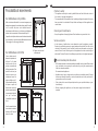
Possibilità di inserimento
Su mobile base con portina
Nella costruzione del mobile è necessario vengano presi
adeguati accorgimenti in modo da evitare possibili contatti
con la scatola del piano surriscaldata durante il
funzionamento dello stesso. La soluzione consigliata per
evitare tale inconveniente è illustrata nella figura 1.
Il pannello sotto il piano dovrà essere facilmente rimovibile
per consentire, in caso di intervento dell'assistenza tecnica,
il bloccaggio e lo sbloccaggio del piano.
Su mobile base con forno
Il vano dovrà avere le
dimensioni riportate nel-
le figure 2 e 3 e dovrà
essere munito di sup-
porti per consentire una
efficace aerazione. Due
possibili soluzioni per
evitare eccessivi surri-
scaldamenti sono illu-
strate nelle figure 4 e 5.
L’allacciamento elettrico
del piano e quello del
forno devono essere re-
alizzati separatamente,
sia per ragioni elettriche
che per facilitare
l’estraibilità frontale del
forno.
Pensili o cappe d’aspira-
zione dovranno trovarsi
ad almeno 650 mm dal
piano di cottura.
a
Pannello rimovibile
b
Spazio per eventuali
allacciamenti
60
b
a
30
20
min
Fig.
Fig.
560 min
550 min
Fig. 3
480
591
380
140
30
Fig. 5
120cm
180 cm
2
2
Fig. 4
50 cm
360 cm
2
2
Children's safety
• This appliance must only be used by adults.Make sure that children do not touch
the controls or play with the appliance.
• The exposed parts of this appliance heat up during cooking and remain hot for some
time even after it is switched off.Keep children well away until the appliance has
cooled down.
Cleaning and maintenance
• Keep the appliance thoroughly cleaned.Food residues may cause fire risks.
Service and parts
• In the instance of malfunctions, never attempt to repair the appliance yourself.
Repairs by unskilled persons may cause damage and accidents.First refer to the
contents of this manual.If you do not find the necessary information, contact your
nearest Service Centre.Servicing work on this appliance must be carried out by an
authorised Technical Service Centre.Always request the use of original spare parts.
Environmental protection advice
• All the materials used are environmentally compatible and recyclable.Please make
your contribution to conserving the environment by using the separate waste
collection channels available.
Decommissioned appliances
• Appliances which are no longer used or usable are not worthless waste.Through
environment-friendly disposal, a number of materials used in the production of
your appliance can be recovered.
• Find out about the current disposal options from your specialist dealer, or your
local authority.
• Before scrapping the appliances, cut the power supply lead and make it
unusable.
IT GB

32 17
Pour votre sécurité
Ces avertissements vous sont donnés pour votre sécurité et celle des autres. Nous
vous prions donc de les lire attentivement avant d’installer et d’utiliser l’appareil.
Conservez ce manuel d’instructions pour toute consultation future. Si l’appareil est
vendu ou transféré, assurez-vous que le manuel soit remis au nouvel utilisateur.
Installation
• L’installation de l’appareil et son branchement au réseau électrique doivent être
effectués uniquement par du PERSONNEL QUALIFIE. Avant toute intervention,
vérifier si l’appareil est DEBRANCHE du réseau électrique.
• Il est dangereux de modifier ou d’essayer de modifier les caractéristiques de ce
produit.
• Après avoir enlevé l’appareil de son emballage, s’assurer qu’il n’ait pas été endommagé
et que le câble d’alimentation électrique soit en parfaites conditions. Dans le cas
contraire, s’adresser au revendeur avant de mettre l’appareil en marche.
• Le fabricant décline toute responsabilité au cas où les normes de prévention contre
les accidents ne seraient pas respectées.
• S’assurer que l’air puisse circuler librement autour de l’appareil. Une mauvaise
ventilation produit une carence en oxygène.
• S’assurer que l'appareil soit alimenté avec le type de gaz indiqué sur l’étiquette
adhésive, placée près du tuyau de raccordement au réseau du gaz.
• L'utilisation d’un appareil de cuisson à gaz produit de la chaleur et de l’humidité
dans la pièce où il est installé. Vérifier si celle-ci est bien aérée en maintenant
ouvertes et efficaces les prises d’air ou en installant une hotte d’aspiration
avec conduit d’évacuation.
• Si l’appareil est utilisé souvent et pour un temps prolongé, rendre l’aération
plus efficace, par exemple en ouvrant une fenêtre ou en augmentant la
puissance de l'aspirateur électrique, s’il est installé.
Pendant l’utilisation
• Ce produit a été conçu pour la cuisson d’aliments, à l’intérieur d’habitations communes,
sans but professionnel. Eviter de l’utiliser pour tout autre usage.
• Après avoir utilisé l’appareil, s’assurer que toutes les commandes soient en position
“FERME” ou “ETEINT”.
• Si l’on utilise une prise de courant près de cet appareil, faire attention que les câbles
des électroménagers que l’on est en train d’utiliser ne le touchent pas et soient
suffisamment éloignés des parties chaudes de cet appareil.
For Your Safety
These instructions have been drawn up for your safety and that of others. You are
therefore requested to read them carefully before installing and using the appliance.
Keep this instruction manual for future reference as necessary. If the appliance is sold
or moved, make sure that the manual is handed over to the new user.
Installation
• Installation of the appliance and its connection to the electrical mains must only
be carried out by QUALIFIED STAFF.Before any procedure, it is important to
check that the appliance is DISCONNECTED from the electrical mains.
• It is risky to modify or attempt to modify the characteristics of this product.
• After removing the appliance from the packaging, make sure that it is undamaged
and that the electrical lead is in perfect condition.Otherwise, contact your dealer
before putting the appliance into operation.
• The Manufacturer declines all responsibility in case of failure to comply with the
accident prevention regulations.
• Make sure that air is able to circulate freely around the appliance.Poor ventilation
produces a shortage of oxygen.
• Make sure that the appliance is supplied with the type of gas indicated on the relative
sticker next to the mains gas connection pipe.
• Use of a gas cooking appliance produces heat and moisture in the room in
which it is installed.Ensure that the room is well ventilated by keeping the air
intakes open and in good working order or by installing an extractor hood
with discharge pipe.
• If the appliance is used intensively for a long time the effectiveness of the
ventilation will have to be increased, for example by opening a window or
increasing the power of any electric extractor fan.
During use
• This product is designed to cook foods inside ordinary homes and for non-professional
purposes.It should not be used for any other purpose.
• After using the appliance, make sure that all controls are in "CLOSED" or "OFF"
position.
• If you use an electrical socket close to this appliance, take care that the cables of
the appliances you are using do not touch it and are far enough away from the hot
parts of this appliance.
GB FR

18 31
Sécurité des enfants
• Cet appareil ne doit être utilisé que par des adultes. S’assurer que les enfants ne
touchent pas les commandes ou ne jouent pas avec l’appareil.
• Les parties exposées de cet appareil chauffent pendant la cuisson et restent chaudes
pendant un certain temps, même après l’extinction. Ne pas laisser les enfants
s’approcher de l’appareil tant qu’il n’est pas refroidi.
Nettoyage et entretien
• L’appareil doit toujours être très propre. Les résidus d’aliment peuvent être la cause
d’incendie.
Service après-vente et pièces de rechange
• Dans le cas de problèmes de fonctionnement, il ne faut jamais essayer de réparer
soi-même l’appareil. Les réparations effectuées par des personnes non compétentes
peuvent causer des dommages et des accidents. Tout d’abord, consulter ce manuel.
Si l’on ne trouve pas les informations désirées, contacter le Centre de Dépannage
le plus proche. La réparation de cet appareil doit être effectué par un Centre de
Dépannage autorisé. Il faut toujours demander l’utilisation de pièces de rechange
d’origine.
Conseils pour la protection de l’environne-
ment
• Tous les matériaux utilisés sont compatibles avec l’environnement et recyclables.
Il faut donc contribuer à la conservation de l’environnement en s’adressant aux
Centres de ramassage prévus dans le pays d’utilisation.
Elimination d’un appareil qui n’est plus utilisé
• Les appareils qui ne sont plus utilisés ou qui ne sont plus utilisables ne sont pas
des déchets sans valeur. Par l’élimination écologique, différents matériaux utilisés
pour la production de votre appareil peuvent être récupérés.
• S’informer des possibilités actuelles d’élimination auprès d’un revendeur spécialisé
ou auprès de la Mairie du lieu de résidence.
• Avant d’éliminer l’appareil, couper le câble d’alimentation afin de le rendre
inutilisable.
Ces instructions ne sont valables que pour les pays de destination dont les
symboles d’identification figurent sur la couverture du manuel d’instructions
et sur l’appareil.
Possibilité d’encastrement
Sur meuble de base avec porte
Pour la construction du meuble, prendre des précautions
afin de ne pas avoir de contacts possibles avec la cuve
de la table surchauffée pendant son fonctionnement. La
solution conseillée pour éviter cet inconvénient est illustrée
dans la figure 1.
Le panneau sous la table de cuisson devra pouvoir être
enlevé facilement pour permettre, lors d’une intervention
de l'assistance technique, le blocage et le déblocage de
la table.
60
b
a
30
20
min
Fig. 1
Sur meuble de base avec four
L’emplacement devra
avoir les dimensions re-
portées dans les figures
2 et 3 et être muni de
supports pour permettre
une aération efficace.
Deux solutions possibles
pour éviter des surchauf-
fes excessives sont illu-
strées dans les figures
4 et 5.
Le branchement électri-
que de la table de cuis-
son et celui du four doi-
vent être réalisés
séparément, aussi bien
pour des raisons électri-
ques que pour faciliter
l’extraction frontale du
four.
Meubles suspendus ou
hottes d’aspiration de-
vront se trouver à au mo-
ins 650 mm de la table
de cuisson.
a
Panneau extractible
b
Espace pour d’éventuels
branchements
Fig. 5
120cm
180 cm
2
2
Fig. 4
50 cm
360 cm
2
2
Fig. 2
560 min
550 min
Fig. 3
480
591
380
140
30
FR FR

30 19
Guide à la lecture des instructions
Les symboles suivants vous aideront pour la lecture des instructions:
Informations de sécurité
Instructions “Pas à pas”
Suggestions et Conseils
Informations liées à la protection de l’environnement
Introduction et fixation
Avant d’introduire la table dans la découpe,
positionner le joint approprié sur le bord
inférieur de la table (Fig E).
Il est important de fixer ce joint de façon
uniforme, sans interruptions ou superposi-
tions, pour empêcher des infiltrations de
liquide sous la table de cuisson.
1) Enlever les grilles et les chapeaux des
brûleurs et retourner la table de cuisson en
faisant attention de ne pas endommager les
bougies d’allumage et les thermocouples.
2) Positionner le joint sur le bord inférieur de
la table comme décrit dans l’illustration ci-
contre.
3) Poser la table de cuisson dans la découpe
et la pousser vers le bas, de façon à ce que
la table soit en position stable sur le meuble,
comme indiqué dans l’illustration. Les ressorts
latéraux assureront la fixation (Fig F).
4) Eliminer avec un cutter la point en excès
du les bords du table (Fig G).
Une paroi latérale de hauteur supérieure à celle de la table de cuisson devra se trouver
à 150 mm. minimum de la découpe pour l’encastrement.
Les dimensions de la table de cuisson et de la découpe sont indiquées sur la figure
ci-dessus.
Fig. F
Fig. E
Fig. G
a
A) joint
a
Sommaire
Pour l’Utilisateur
Pour votre sécurité.................................................................17
Description de la table de cuisson .........................................20
Instructions pour l’utilisation...................................................20
Nettoyage et maintenance.....................................................22
Pour l’Installateur
Caractéristiques techniques...................................................24
Instructions pour l’installateur.................................................25
Branchement électrique.........................................................27
Adaptation aux différents types de gaz..................................28
L’encastrement.......................................................................29
Cet appareil est conforme aux Directives CEE suivantes:
- 73/23 et 90/683 (relatives à la Basse Tension);
- 89/336 (relative à la Compatibilité Electromagnétique);
- 90/396 (relative aux Appareils à Gaz)
- 93/68 (relative aux Normes Générales)
et modifications successives.
FR FR

20 29
Description de la table de cuisson
1.Table de cuisson
2.Brûleur semi-rapide
3.Brûleur auxiliaire
4.Brûleur rapide
5.Manettes des brûleurs
6.Brûleur T.F.
6
5
2
1
3
2
6
1
5
Instructions d’emploi
B
A
C
A
B
C
D
Fig. 1
A-Chapeau du brûleur
B-Bougie d’allumage
C- Thermocouple
D-Chapeau brûleur
“triple flamme”
Les manettes de la table de
cuisson
Sens des symboles placés sur les manettes:
aucune arrivée de gaz
débit maximum de gaz
débit réduit de gaz
Toutes les positions de fonctionnement doivent être
choisies entre les positions maxi. et mini., jamais
entre le maximum et l’extinction.
(symbole présent pour la version avec
allumage sur la manette.)
2
2
5
2
5
3
6
2
4
1
3
4
1
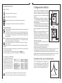
Réglage du débit réduit
1) Allumer le brûleur comme décrit précédemment.
2) Porter le robinet sur la position de débit réduit.
3) Extraire les manettes.
4) Avec un tournevis à tranchant fin, agir sur le by-pass placé à côté de la tige du
robinet (voir fig. A). Pour le gaz butane / propane, visser à fond le by-pass en
sens horaire.
Le résultat devra être une petite flamme homogène et régulière sur toute la
couronne du brûleur. Pour la version Dual Triple Flamme voir fig. B by pass 1
Brûleur central by pass 2 les deux brûleurs.
5) Vérifier la stabilité des flammes en tournant rapidement le robinet de la position
maxi. à la position mini.
Ces tables sont prévues pour l’encastrement dans des meubles à éléments de cuisine
ayant une profondeur de 600 mm maximum et des caractéristiques adéquates.
L’encastrement
680
510
A
480
560
70
50
600
1
2
B
FR FR
La pagina si sta caricando...
La pagina si sta caricando...
La pagina si sta caricando...
La pagina si sta caricando...
-
 1
1
-
 2
2
-
 3
3
-
 4
4
-
 5
5
-
 6
6
-
 7
7
-
 8
8
-
 9
9
-
 10
10
-
 11
11
-
 12
12
-
 13
13
-
 14
14
-
 15
15
-
 16
16
-
 17
17
-
 18
18
-
 19
19
-
 20
20
-
 21
21
-
 22
22
-
 23
23
-
 24
24


High One MPG 75 A Manuale del proprietario
- Tipo
- Manuale del proprietario
in altre lingue
- English: High One MPG 75 A Owner's manual
- français: High One MPG 75 A Le manuel du propriétaire
Altri documenti
-
Aeg-Electrolux 95750G-B Manuale utente
-
-
Iberna PCPI471/6AS Manuale utente
-
Progress PAG7530E-F Manuale utente
-
-
Freggia HB640B Manuale utente
-
Electrolux EHT9780K Manuale utente
-
AEG 35743G-m/CZ Manuale utente
-
-
Lofra PB96MFT/C Manuale del proprietario