

Precautions
Your new display unit and this manual 3
Important safeguards 3
Connecting the system
Precautions before connecting the
system 4
Before installing this product 4
To prevent damage 5
– Notice for the blue/white lead 5
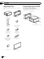
Parts supplied 6
Connecting the system 7
Connecting the power cord 8
Connecting the control line cable 10
When connecting to separately sold power
amp 11
When connecting to separately sold
subwoofer 12
When connecting a rear view camera 13
Installation
Precautions before installation 14
To avoid electromagnetic interference 14
Before installing 14
Installing this product 15
– Installation notes 15
– Parts supplied 16
– Before installing this product 16
– Installation with the holder and side
bracket 17
– Installation using the screw holes on
the side of this product 17
Installing the GPS aerial 18
– Installation notes 18
– Parts supplied 18
– When installing the aerial inside the
vehicle (on the dashboard or rear
shelf) 19
Installing the microphone 20
– Parts supplied 20
– Mounting on the sun visor 20
– Installation on the steering column 20
After installation
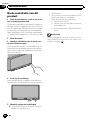
After installing this product 22
Contents
Engb
2

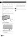
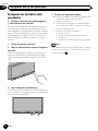
Your new display unit and
this manual
! Do not operate this product, any applica-
tions, or the rear view camera option (if pur-
chased) if doing so will divert your attention
in any way from the safe operation of your
vehicle. Always observe safe driving rules
and follow all existing traffic regulations. If
you experience difficulty in operating this
product or reading the display, park your
vehicle in a safe location and apply the
handbrake before making the necessary
adjustments.
! Do not install this product where it may (i)
obstruct the driver’s vision, (ii) impair the
performance of any of the vehicle’s operat-
ing systems of safety features, including
airbags, hazard lamp buttons, or (iii) impair
the driver’s ability to safely operate the vehi-
cle. In some cases, it may not be possible
to install this product because of the vehi-
cle type or the shape of the vehicle interior.
! This manual explains how to install this
product in your vehicle. Operation of this
product is explained in the separate man-
uals.
Important safeguards
WARNING
Pioneer does not recommend that you install
this product yourself. We recommend that
only authorised Pioneer service personnel,
who have special training and experience in
mobile electronics, set up and install this
product. NEVER SERVICE THIS PRODUCT
YOURSELF. Installing or servicing this pro-
duct and its connecting cables may expose
you to the risk of electric shock or other ha-
zards, and can cause damage to the product
that is not covered by warranty.
! Read this manual fully and carefully before
installing this product.
! Keep this manual handy for future refer-
ence.
! Pay close attention to all warnings in this
manual and follow the instructions care-
fully.
! Traffic restrictions and advisories are al-
ways more important than guidance given
by a third-party navigation/mapping iPhone
application. Always obey current traffic re-
strictions, even if the application provides
contrary advice.
! As with any accessory in your vehicle’s in-
terior, this product should not divert your
attention from the safe operation of your
vehicle. If you experience difficulty in oper-
ating this product or reading the display,
please make adjustments while safely
parked.
! Please remember to wear your seat belt at
all times while operating your vehicle. If
you are in an accident, your injuries can be
considerably more severe if your seat belt
is not properly fastened.
! Certain country and government laws may
prohibit or restrict the placement and use
of this product in your vehicle. Please com-
ply with all applicable laws and regulations
regarding the use, installation and opera-
tion of this product.
Engb
3
English
Section
01
Precautions

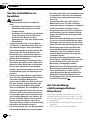
Precautions before
connecting the system
CAUTION
! If you decide to perform the installation
yourself, and have special training and ex-
perience in the mobile electronics instal-
lations, please carefully follow all of the
steps in the installation manual.
! Secure all wiring with cable clamps or
electrical tape. Do not allow any bare wir-
ing to remain exposed.
! Do not directly connect the yellow lead of
this product to the vehicle battery. If the
lead is directly connected to the battery,
engine vibration may eventually cause
the insulation to fail at the point where
the wire passes from the passenger com-
partment into the engine compartment. If
the yellow lead’s insulation tears as a re-
sult of contact with metal parts, short-cir-
cuiting can occur, resulting in
considerable danger.
! It is extremely dangerous to allow cables
to become wound around the steering col-
umn or gearstick. Be sure to install this
product, its cables, and wiring away in
such so that they will not obstruct or hin-
der driving.
! Make sure that the cables and wires will
not interfere with or become caught in
any of the vehicle’s moving parts, espe-
cially the steering wheel, gearstick, hand-
brake, sliding seat tracks, doors, or any of
the vehicle’s controls.
! Do not route wires where they will be ex-
posed to high temperatures. If the insula-
tion heats up, wires may become
damaged, resulting in a short circuit or
malfunction and permanent damage to
the product.
! Do not cut the GPS aerial cable to shorten
it or use an extension to make it longer.
Altering the aerial cable could result in a
short circuit or malfunction.
! Do not shorten any leads. If you do, the
protection circuit (fuse holder, fuse resis-
tor or filter, etc.) may fail to work properly.
! Never feed power to other electronic pro-
ducts by cutting the insulation of the
power supply lead of this product and tap-
ping into the lead. The current capacity of
the lead will be exceeded, causing over-
heating.
Before installing this product
! Use this unit with a 12-volt battery and ne-
gative earthing only. Failure to do so may
result in a fire or malfunction.
! To avoid shorts in the electrical system, be
sure to disconnect the (–) battery cable be-
fore installation.
Engb
4
Section
02
Connecting the system

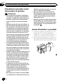
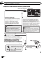
To prevent damage
WARNING
! Use speakers over 50 W (output value)
and between 4 W to 8 W (impedance value).
Do not use 1 W to 3 W speakers for this
unit.
! The black lead is earth. Please earth this
lead separately from the earth of high-cur-
rent products such as power amps. Do not
earth more than one product together
with the earth from another product. For
example, you must separately earth any
amp unit away from the earth of this pro-
duct. Connecting earths together can
cause a fire and/or damage the products if
their earths became detached.
! When replacing the fuse, be sure to only
use a fuse of the rating prescribed on this
product.
! When disconnecting a connector, pull the
connector itself. Do not pull the lead, as
you may pull it out of the connector.
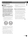
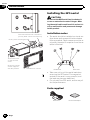
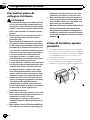
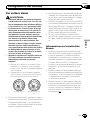
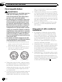
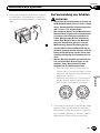
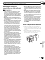
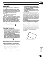
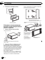
! This product cannot be installed in a vehi-
cle without ACC (accessory) position on
the ignition switch.
A
C
C
O
N
S
T
A
R
T
O
F
F
O
N
S
T
A
R
T
O
F
F
ACC position No ACC position
! To avoid short-circuiting, cover the discon-
nected lead with insulating tape. It is espe-
cially important to insulate all unused
speaker leads, which if left uncovered may
cause a short circuit.
! Refer to the owner’s manual for details on
connecting the power amp and other units,
then make connections accordingly.
! Since a unique BPTL circuit is employed,
do not directly earth the * side of the
speaker lead or connect the * side of an-
other side of the speaker lead together. Be
sure to connect the * side of the speaker
lead to the * side of the speaker lead on
this product.
! If the RCA pin jack on this product will not
be used, do not remove the caps attached
to the end of the connector.
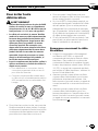
Notice for the blue/white lead
! When the ignition switch is turned on (ACC
ON), a control signal is output through the
blue/white lead. Connect to an external
power amp’s system remote control term-
inal (max. 300 mA 12 V DC). The control sig-
nal is output through the blue/white lead,
even if the AV source is switched off.
! Be sure not to use this lead as the power
supply lead for the external power amps.
Such connection could cause excessive
current drain and malfunction.
! Be sure not to use this lead as the power
supply lead for the auto-aerial or aerial
booster. Such connection could cause ex-
cessive current drain and malfunction.
Engb
5
English
Section
02
Connecting the system

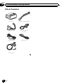
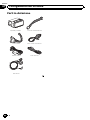
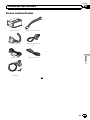
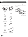
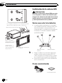
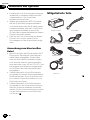
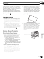
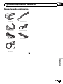
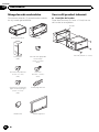
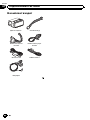
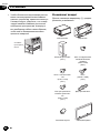
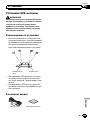
Parts supplied
This product Power cord
Output cable Control line cable
GPS aerial iPhone cable
Microphone
Engb
6
Section
02
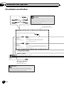
Connecting the system

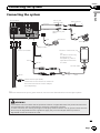
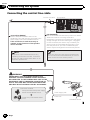
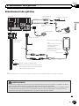
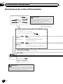
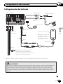
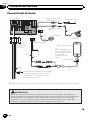
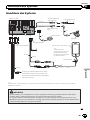
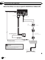
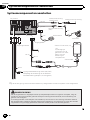
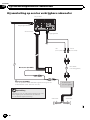
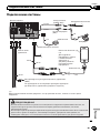
Connecting the system
WARNING
· To avoid the risk of accident and the potential violation of applicable laws, this product should never
be used while the vehicle is being driven except for navigation purposes.
· In some countries, the viewing of images on a display inside a vehicle even by persons other than the
driver may be illegal. Where such regulations apply they must be obeyed and this product’s
App-based content should not be used.
(*2)
For details concerning
operations and
compatibility, refer to
Important Information
for Users.
Aerial jack
(RADIO ANT)
Microphone
3 m
GPS aerial
Vehicle aerial
4 m
iPhone cable
iPhone or iPod touch (*2)
This product
Control line cable
Wired remote input (SWC)
Please refer to the instruction manual for
the Hard-wired remote control adaptor
(sold separately).
Microphone jack
(MIC)
Output cable
(*1)
(*1)
Make sure that the three yellow, green and blue connectors are attached before connecting the system.
2 m
25 cm
25 cm
25 cm
8.5 cm
8.5 cm
Engb
7
English
Section
02
Connecting the system

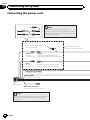
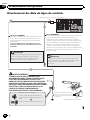
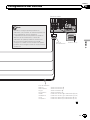
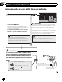
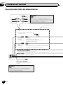
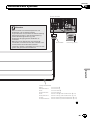
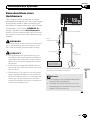
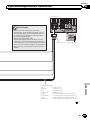
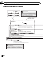
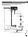
Connecting the power cord
ISO connector
Orange/white (ILLUMI)
To lighting switch terminal.
Black (GND)
To vehicle (metal) body.
In some vehicles, the ISO connector may be divided
into two. In this case, be sure to connect to both
connectors.
Note
Yellow (*2)
Back-up
(or accessory)
Red (*4)
Accessory
(or back-up)
Yellow (*1)
To terminal supplied with power
regardless of ignition switch position.
Red (*3)
To electric terminal controlled by
ignition switch (12 V DC) ON/OFF.
Connect leads of the
same colour to each other.
*2
*4
*3
*5
Depending on the types of vehicles, the
function of *3 and *5 may be different. In this
case, be sure to connect *2 to *5 and *4 to *3
as shown in the figure.
Note
Blue/white (P.CONT)
To P.CONT of control line cable.
*1
Cap (*1)
When not using this terminal, do
not remove the cap.
Engb
8
Section
02
Connecting the system

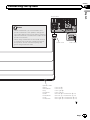
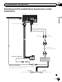
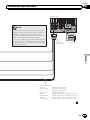
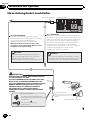
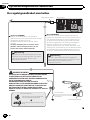
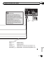
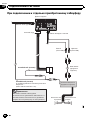
This product
Notes
· When a subwoofer (*6) is connected to this
product instead of a rear speaker, change the
rear output setting in the initial setting. (Refer to
Operation Manual.) The subwoofer output of this
product is monaural.
· When using a subwoofer of 70 W (2 Ω), be sure
to connect with violet and violet/black leads of
this product. Do not connect anything with
green and green/black leads.
Fuse (15 A)
Speaker leads
White: Front left
White/black: Front left
Grey: Front right
Grey/black: Front right
Green: Rear left or Subwoofer (*6)
Green/black: Rear left or Subwoofer (*6)
Violet: Rear right or Subwoofer (*6)
Violet/black: Rear right or Subwoofer (*6)
Power cord
Engb
9
English
Section
02
Connecting the system

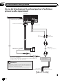
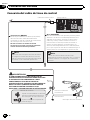
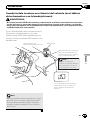
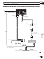
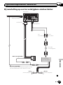
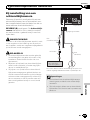
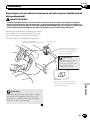
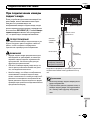
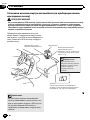
Connecting the control line cable
Control line cable
Pink (REVERSE)
This is connected so that the this product can detect
whether the vehicle is moving forwards or
backwards. Connect the pink lead to the lead whose
voltage changes when the reverse gear is engaged.
Unless connected, the sensor may not detect your
vehicle travelling forward/backward properly, and
thus the position of your vehicle detected by the
sensor may be misaligned from the actual position.
GREEN/WHITE LEAD AT POWER CONNECTOR IS
DESIGNED TO DETECT PARKED STATUS AND MUST
BE CONNECTED TO THE POWER SUPPLY SIDE OF THE
HANDBRAKE SWITCH. IMPROPER CONNECTION OR
USE OF THIS LEAD MAY VIOLATE APPLICABLE LAW
AND MAY RESULT IN SERIOUS INJURY OR DAMAGE.
When you use a rear view camera, please make
sure to connect this lead. Otherwise you cannot
switch to the rear view camera picture.
Power supply side
Earth side
Handbrake switch
This product
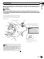
Connection method
Clamp the lead of the power supply
side of the handbrake switch.
Clamp firmly with needle-nosed
pliers.
WARNING
Note
Green/white (BRAKE)
Used to detect the ON/OFF status of the
handbrake. This lead must be connected to the
power supply side of the handbrake switch.
If this connection is made incorrectly or
omitted, certain functions of this product
will be unusable.
The position of the handbrake switch vary
depending on the vehicle model. For details,
consult your authorised Pioneer dealer or an
installation professional.
Note
Engb
10
Section
02
Connecting the system

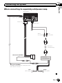
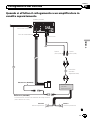
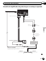
When connecting to separately sold power amp
This product
To system control terminal of the power amp
(max. 300 mA 12 V DC).
Blue/white (P.CONT)
Left Right
Power amp
(sold separately)
Rear speaker Rear speaker
Control line cable
Output cable
Power cord
Blue/white (P.CONT)
RCA cable
(sold separately)
White
(FULL/SW)
Red
(FULL/SW)
Engb
11
English
Section
02
Connecting the system

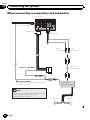
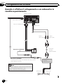
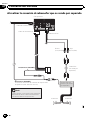
When connecting to separately sold subwoofer
This product
To system control terminal of the power amp
(max. 300 mA 12 V DC).
Blue/white (P.CONT)
White
(FULL/SW)
Red
(FULL/SW)
Power amp
(sold separately)
Subwoofer
Subwoofer
Control line cable
Output cable
Power cord
Blue/white (P.CONT)
RCA cable
(sold separately)
You can change the RCA output of the subwoofer
depending on your subwoofer system.
(Refer to Operation Manual.)
Note
Engb
12
Section
02
Connecting the system

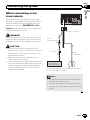
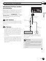
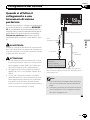
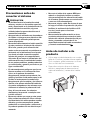
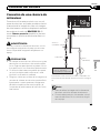
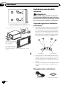
When connecting a rear
view camera
When this product is used with a rear view
camera, it is possible to automatically switch
from the video to rear view image when the
gearstick is moved to REVERSE (R). Rear
Camera mode also allows you to check what
is behind you while driving.
WARNING
When you connect the rear view camera, do not
forget to adjust the setting of this product so as
to display mirror reversed images on the screen.
CAUTION
! The rear view camera is used as an aid to
keep an eye on trailers, or backing into a tight
parking spot. Do not use this function for en-
tertainment purposes.
! Objects in rear view may appear closer or
more distant than in reality.
! Please note that the image area shown by the
rear view camera may differ slightly when full-
screen images are displayed when backing
and when checking the rear of the vehicle
while moving forward.
(REVERSE)
Pink
Control line cable
Yellow
(CAMERA VIDEO)
This product
(e.g. ND-BC4)
(sold separately)
RCA cable
Rear view camera
For more details about the wiring, refer to Connecting
the control line cable on page 10.
Notes
! To display the rear view camera image, set
the rear view camera to on.
! Connect this product to the rear view cam-
era only. Do not connect to any other equip-
ment.
Engb
13
English
Section
02
Connecting the system

Precautions before
installation
CAUTION
! Never install this product in places where,
or in a manner that:
— Could injure the driver or passengers if
the vehicle stops suddenly.
— May interfere with the driver’s opera-
tion of the vehicle, such as on the floor
in front of the driver’s seat, or close to
the steering wheel or gearstick.
! Make sure there is nothing behind the
dashboard or panelling when drilling
holes in them. Be careful not to damage
fuel lines, brake lines, electronic compo-
nents, communication wires or power
cables.
! When using screws, do not allow them to
come into contact with any electrical lead.
Vibration may damage wires or insulation,
leading to a short circuit or other damage
to the vehicle.
! To ensure proper installation, be sure to
use the supplied parts in the manner spe-
cified. If any parts are not supplied with
this product, use compatible parts in the
manner specified after you have the parts’
compatibility checked by your dealer. If
parts other than supplied or compatible
ones are used, they may damage internal
parts of this product or they may work
loose and the product may become de-
tached.
! It is extremely dangerous to allow cables
to become wound around the steering col-
umn or gearstick. Be sure to install this
product, its cables, and wiring away in
such so that they will not obstruct or hin-
der driving.
! Make sure that leads cannot get caught in
a door or the sliding mechanism of a seat,
resulting in a short circuit.
! Please confirm the proper function of
your vehicle’s other equipment after in-
stallation of this product.
! Do not install this product where it may (i)
obstruct the driver’s vision, (ii) impair the
performance of any of the vehicle’s oper-
ating systems or safety features, includ-
ing airbags, hazard lamp buttons or (iii)
impair the driver’s ability to safely oper-
ate the vehicle.
! Install this product between the driver’s
seat and front passenger seat so that it
will not be hit by the driver or passenger if
the vehicle stops quickly.
! Never install this product in front of or
next to the place in the dashboard, door,
or pillar from which one of your vehicle’s
airbags would deploy. Please refer to your
vehicle’s owner’s manual for reference to
the deployment area of the frontal air-
bags.
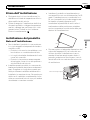
To avoid electromagnetic
interference
In order to prevent interference, set the follow-
ing items as far as possible from this product,
other cables or leads:
! FM, MW/LW aerial and its lead
! GPS aerial and its lead
In addition, you should lay or route each aerial
lead as far as possible from other aerial leads.
Do not bind, lay or route them together, or
cross them. Electromagnetic noise will in-
crease the potential for errors in the vehicle’s
location display.
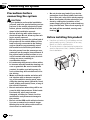
Before installing
! Consult with your nearest dealer if installa-
tion requires drilling holes or other modifi-
cations of the vehicle.
! Before making a final installation of this
product, temporarily connect the wiring to
confirm that the connections are correct
and the system works properly.
Engb
14
Section
03
Installation

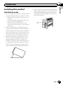
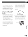
Installing this product
Installation notes
! Do not install this product in places subject
to high temperatures or humidity, such as:
— Places close to a heater, vent or air con-
ditioner.
— Places exposed to direct sunlight, such
as on top of the dashboard.
— Places that may be exposed to rain,
such as close to the door or on the vehi-
cle’s floor.
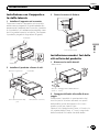
! Install this product in an area strong en-
ough to bear its weight. Choose a position
where this product can be firmly installed,
and install it securely. If this product is not
securely installed, the current location of
the vehicle cannot be displayed correctly.
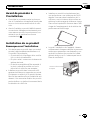
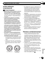
! Install this product horizontally on a sur-
face within 0 to 60 degrees tolerance. Im-
proper installation of the unit with the
surface tilted more than these tolerances
increases the potential for errors in the ve-
hicle’s location display, and might other-
wise cause reduced display performance.
60°
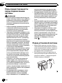
! When installing, to ensure proper heat dis-
persal when using this unit, make sure you
leave ample space behind the rear panel
and wrap any loose cables so they are not
blocking the vents.
Leave ample
space
5 cm
5 cm
Engb
15
English
Section
03
Installation

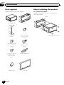
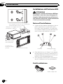
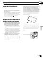
Parts supplied
Parts marked (*) are pre-installed.
The display unit Holder*
Side bracket*
(2 pcs.)
Truss head screw
(5 mm × 6 mm)
(8 pcs.)
Flush surface screw
(5 mm × 7 mm)
(4 pcs.)
Screw*
(2.6 mm × 5 mm)
(4 pcs.)
Screw for fixing the
side bracket*
(5 mm × 7 mm)
(4 pcs.)
Double-ended screw
Rubber bush Trim ring
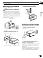
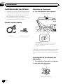
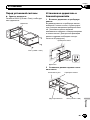
Before installing this product
% Remove the holder.
Loosen the screws (2.6 mm × 5 mm) to re-
move the holder.
Holder
Screw (2.6 mm × 5 mm)
Engb
16
Section
03
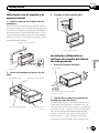
Installation

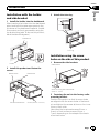
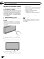
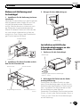
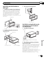
Installation with the holder
and side bracket
1 Install the holder into the dashboard.
After inserting the holder into the dashboard,
select and bend the tabs appropriate to the
thickness of the dashboard material. (Install
this product as firmly as possible using the
top and bottom tabs. To secure this product,
bend the tabs 90 degrees.)
Dashboard
Holder
2 Install this product and fasten the
screws.
Rubber bush Dashboard
Double-ended screw Screw (2.6 mm × 5 mm)
3 Attach the trim ring.
Trim ring
Installation using the screw
holes on the side of this product
1 Remove the side brackets.
Side bracket
Screw for fixing the side bracket
(5 mm × 7 mm)
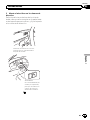
2 Fastening the unit to the factory radio-
mounting bracket.
Position this product so that its screw holes
are aligned with the screw holes of the brack-
et, and tighten the screws at three or four loca-
tions on each side.
Use either the truss head screws (5 mm ×
6 mm) or flush surface screws (5 mm ×
7 mm), depending on the shape of the brack-
et’s screw holes.
Engb
17
English
Section
03
Installation

If the tab interferes with installation,
you may bend it down out of the way.
Dashboard or console
T
russ head screw
or flush surface
screw
Be sure to use the
screws supplied
with this product.
Factory radio-mounting bracket
Installing the GPS aerial
CAUTION
Do not cut the GPS aerial lead to shorten it
or use an extension to make it longer. Alter-
ing the aerial cable could result in a short cir-
cuit or malfunction and permanent damage
to this product.
Installation notes
! The aerial should be installed on a level sur-
face where radio waves will be blocked as
little as possible. Radio waves cannot be re-
ceived by the aerial if reception from the sa-
tellite is blocked.
Dashboard Rear shelf
! Take care not to pull the aerial lead when
removing the GPS aerial. The magnet at-
tached to the aerial is very powerful, and
the lead may become detached.
! Do not paint the GPS aerial, as this may af-
fect its performance.
Parts supplied
GPS aerial Double-sided tape
Engb
18
Section
03
Installation

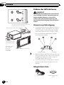
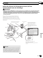
When installing the aerial inside the vehicle (on the dashboard or
rear shelf)
WARNING
Do not install the GPS aerial over any sensors or vents on the dashboard of the vehicle, as
doing so may interfere with the proper functioning of such sensors or vents and may compro-
mise the ability of the double-sided tape under the GPS aerial to properly and securely affix to
the dashboard.
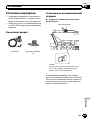
Affix the double-sided tape on the surface as
level as possible where the GPS aerial faces
the window. Place the GPS aerial on the dou-
ble-sided tape.
The double-sided tape
contains a strong adhesive
which may leave a mark on
the surface if it is removed.
Note
Clamps
Use separately sold clamps
to secure the lead where necessary
inside the vehicle.
GPS aerial
Double-sided tape
Peel off the protective sheet.
Make sure the surface is free of
moisture, dust, grime, oil, etc.,
before affixing the double-sided
tape.
Note
Some models use window glass that does not
allow signals from GPS satellites to pass
through. On such models, install the GPS aer-
ial on the outside of the vehicle.
Engb
19
English
Section
03
Installation

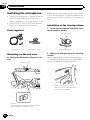
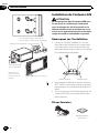
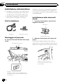
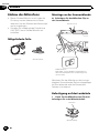
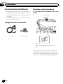
Installing the microphone
! Install the microphone in a place where its
direction and distance from the driver
make it easiest to pick up the driver’s voice.
! Be sure to turn off (ACC OFF) the product
before connecting the microphone.
Parts supplied
Microphone Microphone holder
Mounting on the sun visor
% Attach the microphone clip to the sun
visor.
Microphone clip
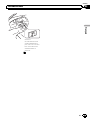
Clamps
Use separately sold clamps to secure the lead
where necessar y inside the vehicle.
Install the microphone on the sun visor when
it is in the up position. It cannot recognise the
driver’s voice if the sun visor is in the down po-
sition.
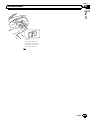
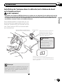
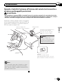
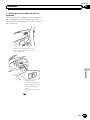
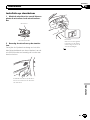
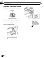
Installation on the steering column
1 Unclip the microphone and place it into
the microphone holder.
Microphone
Microphone holder
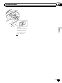
2 Mount the microphone on the steering
column.
Peel the backing from the double-sided tape
on the back of the microphone holder and at-
tach the holder to the steering column.
Install the microphone on the
steering column, keeping it away
from the steering wheel.
Engb
20
Section
03
Installation
La pagina si sta caricando...
La pagina si sta caricando...
La pagina si sta caricando...
La pagina si sta caricando...
La pagina si sta caricando...
La pagina si sta caricando...
La pagina si sta caricando...
La pagina si sta caricando...
La pagina si sta caricando...
La pagina si sta caricando...
La pagina si sta caricando...
La pagina si sta caricando...
La pagina si sta caricando...
La pagina si sta caricando...
La pagina si sta caricando...
La pagina si sta caricando...
La pagina si sta caricando...
La pagina si sta caricando...
La pagina si sta caricando...
La pagina si sta caricando...
La pagina si sta caricando...
La pagina si sta caricando...
La pagina si sta caricando...
La pagina si sta caricando...
La pagina si sta caricando...
La pagina si sta caricando...
La pagina si sta caricando...
La pagina si sta caricando...
La pagina si sta caricando...
La pagina si sta caricando...
La pagina si sta caricando...
La pagina si sta caricando...
La pagina si sta caricando...
La pagina si sta caricando...
La pagina si sta caricando...
La pagina si sta caricando...
La pagina si sta caricando...
La pagina si sta caricando...
La pagina si sta caricando...
La pagina si sta caricando...
La pagina si sta caricando...
La pagina si sta caricando...
La pagina si sta caricando...
La pagina si sta caricando...
La pagina si sta caricando...
La pagina si sta caricando...
La pagina si sta caricando...
La pagina si sta caricando...
La pagina si sta caricando...
La pagina si sta caricando...
La pagina si sta caricando...
La pagina si sta caricando...
La pagina si sta caricando...
La pagina si sta caricando...
La pagina si sta caricando...
La pagina si sta caricando...
La pagina si sta caricando...
La pagina si sta caricando...
La pagina si sta caricando...
La pagina si sta caricando...
La pagina si sta caricando...
La pagina si sta caricando...
La pagina si sta caricando...
La pagina si sta caricando...
La pagina si sta caricando...
La pagina si sta caricando...
La pagina si sta caricando...
La pagina si sta caricando...
La pagina si sta caricando...
La pagina si sta caricando...
La pagina si sta caricando...
La pagina si sta caricando...
La pagina si sta caricando...
La pagina si sta caricando...
La pagina si sta caricando...
La pagina si sta caricando...
La pagina si sta caricando...
La pagina si sta caricando...
La pagina si sta caricando...
La pagina si sta caricando...
La pagina si sta caricando...
La pagina si sta caricando...
La pagina si sta caricando...
La pagina si sta caricando...
La pagina si sta caricando...
La pagina si sta caricando...
La pagina si sta caricando...
La pagina si sta caricando...
La pagina si sta caricando...
La pagina si sta caricando...
La pagina si sta caricando...
La pagina si sta caricando...
La pagina si sta caricando...
La pagina si sta caricando...
La pagina si sta caricando...
La pagina si sta caricando...
La pagina si sta caricando...
La pagina si sta caricando...
La pagina si sta caricando...
La pagina si sta caricando...
La pagina si sta caricando...
La pagina si sta caricando...
La pagina si sta caricando...
La pagina si sta caricando...
La pagina si sta caricando...
La pagina si sta caricando...
La pagina si sta caricando...
La pagina si sta caricando...
La pagina si sta caricando...
La pagina si sta caricando...
La pagina si sta caricando...
La pagina si sta caricando...
La pagina si sta caricando...
La pagina si sta caricando...
La pagina si sta caricando...
La pagina si sta caricando...
La pagina si sta caricando...
La pagina si sta caricando...
La pagina si sta caricando...
La pagina si sta caricando...
La pagina si sta caricando...
La pagina si sta caricando...
La pagina si sta caricando...
La pagina si sta caricando...
La pagina si sta caricando...
La pagina si sta caricando...
La pagina si sta caricando...
La pagina si sta caricando...
La pagina si sta caricando...
La pagina si sta caricando...
La pagina si sta caricando...
La pagina si sta caricando...
La pagina si sta caricando...
La pagina si sta caricando...
La pagina si sta caricando...
La pagina si sta caricando...
-
 1
1
-
 2
2
-
 3
3
-
 4
4
-
 5
5
-
 6
6
-
 7
7
-
 8
8
-
 9
9
-
 10
10
-
 11
11
-
 12
12
-
 13
13
-
 14
14
-
 15
15
-
 16
16
-
 17
17
-
 18
18
-
 19
19
-
 20
20
-
 21
21
-
 22
22
-
 23
23
-
 24
24
-
 25
25
-
 26
26
-
 27
27
-
 28
28
-
 29
29
-
 30
30
-
 31
31
-
 32
32
-
 33
33
-
 34
34
-
 35
35
-
 36
36
-
 37
37
-
 38
38
-
 39
39
-
 40
40
-
 41
41
-
 42
42
-
 43
43
-
 44
44
-
 45
45
-
 46
46
-
 47
47
-
 48
48
-
 49
49
-
 50
50
-
 51
51
-
 52
52
-
 53
53
-
 54
54
-
 55
55
-
 56
56
-
 57
57
-
 58
58
-
 59
59
-
 60
60
-
 61
61
-
 62
62
-
 63
63
-
 64
64
-
 65
65
-
 66
66
-
 67
67
-
 68
68
-
 69
69
-
 70
70
-
 71
71
-
 72
72
-
 73
73
-
 74
74
-
 75
75
-
 76
76
-
 77
77
-
 78
78
-
 79
79
-
 80
80
-
 81
81
-
 82
82
-
 83
83
-
 84
84
-
 85
85
-
 86
86
-
 87
87
-
 88
88
-
 89
89
-
 90
90
-
 91
91
-
 92
92
-
 93
93
-
 94
94
-
 95
95
-
 96
96
-
 97
97
-
 98
98
-
 99
99
-
 100
100
-
 101
101
-
 102
102
-
 103
103
-
 104
104
-
 105
105
-
 106
106
-
 107
107
-
 108
108
-
 109
109
-
 110
110
-
 111
111
-
 112
112
-
 113
113
-
 114
114
-
 115
115
-
 116
116
-
 117
117
-
 118
118
-
 119
119
-
 120
120
-
 121
121
-
 122
122
-
 123
123
-
 124
124
-
 125
125
-
 126
126
-
 127
127
-
 128
128
-
 129
129
-
 130
130
-
 131
131
-
 132
132
-
 133
133
-
 134
134
-
 135
135
-
 136
136
-
 137
137
-
 138
138
-
 139
139
-
 140
140
-
 141
141
-
 142
142
-
 143
143
-
 144
144
-
 145
145
-
 146
146
-
 147
147
-
 148
148
-
 149
149
-
 150
150
-
 151
151
-
 152
152
-
 153
153
-
 154
154
-
 155
155
-
 156
156


in altre lingue
- English: Pioneer SPH-DA01 Installation guide
- français: Pioneer SPH-DA01 Guide d'installation
- español: Pioneer SPH-DA01 Guía de instalación
- Deutsch: Pioneer SPH-DA01 Installationsanleitung
- русский: Pioneer SPH-DA01 Инструкция по установке
- Nederlands: Pioneer SPH-DA01 Installatie gids
Documenti correlati
-
Pioneer SPH-DA02 Guida d'installazione
-
Pioneer AVIC F550 BT Guida utente
-
Pioneer SPH-DA100 Manuale del proprietario
-
Mode AVIC F10 BT Manuale del proprietario
-
Mode AVIC-F20BT Manuale del proprietario
-
Mode AVIC-F950 Manuale del proprietario
-
 Mode AVIC F40 BT Istruzioni per l'uso
-
