
I - 23804 MONTE MARENZO (LC) ITALY
KONG SPA. VIA XXV APRILE, 4 (ZONA INDUSTRIALE)
1
Note: The user is advised to keep the user instructions document for the life of the product.
Applicable to :
Manufacturer :
Certication Body : SATRA Technology Europe Ltd, Bracetown Business Park, Clonee,
Dublin D15 YN2P Ireland (Notied Body 2777)
Ongoing Assessment Body : SGS Fimko Oy, P.O. Box 30 (Särkiniementie 3), 00211 HELSINKI,
Finland (Notified Body 0598)
225020100KK
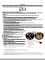
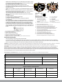
The Retractable Fall Arrester for horizontal usage is classed as a Personal Protective Equipment (PPE) by the European PPE Regulation (EU) 2016/425 and has been shown to
comply with this Regulation through the Harmonized European Standard EN 360:2002 & VG11 RFU # 11.060
CAREFULLY READ THESE INSTRUCTIONS BEFORE USING THIS RETRACTABLE FALL ARRESTER
This Retractable Fall Arrester for horizontal usage is designed to minimise the risk of/provide protection against the danger of falling from heights. However, always remember
that no item of PPE can provide full protection and care must always be taken while carrying out the risk related activity.
PERFORMANCE AND LIMITATIONS OF USE
The equipment has been tested in accordance with EN 360:2002 & as per VG11 RFU # 11.060 and has achieved the following performance levels :
Result/Comment
Achieves required performance as stated in EN 360:2002 (PASS).
Lanyard free from sharp or excessively abrasive surface (PASS).
Lanyard end terminated with a loop, for connection to harness and fall arrest system (PASS).
Lanyard meets static strength requirement (PASS).
After conditioning, it locks & remains locked until released with 5 kg Max. (PASS)
12kN sustained for 3 minutes without release (Wire) (PASS).
15kN sustained for 3 minutes without release (Webbing) (PASS).
When tested with the test mass of 100 kg,
The Arrest force <6.00 kN, Arrest distance <2.00 m (PASS).
Corrosion test in accordance with ISO 9227:1990-24 hours (PASS).
EN 360:2002 test
Clause 4.1
Design & Ergonomics
Clause 4.2
Materials & Construction
Clause 4.3
Locking after Conditioning(EN 364:1993)
Clause 4.4
Static Strength(EN 364:1993)
Clause 4.5
Dynamic Performance(EN 364:1993)
Clause 4.7
Corrosion Resistance (EN 364:1993)
No unnecessary features which add signicantly to overall mass ( Pass).
AS PER VG11 RFU # 11.060
1. Dynamic Performance :
a. Perpendicular to the edge
b. Lateral offset of 1.5 mtr
2. Dynamic Strength
a. Perpendicular to the edge
b. Lateral offset of 1.5 mtr
3. Static Strength after each
Dynamic Strength test
Result/Comment
100 Kg mass held
_
Breaking force <6kN
Breaking distance less than 2 mtr
100 Kg mass held
f=3kN (Cable) 4.5 kN (Textile) 3 mints
POSSIBLE USAGE :
This Retractable Fall Arrester can be used as a part of a fall arrest system or as a part of a restraint system. If using as a part of fall arrest system, a suitable anchor point
(above the user’s head, at least 12kN) shall be used. Attachments to the anchor points and
condition
Material of the Lanyard-
- for wire rope block - 4.8mm Galvanized steel wire. - for webbing block - 25mm polyester textile webbing.
Other equipment shall be made using oval Karabiners to EN362. The equipment
is to be used specically in vertical as well as horizontal
USER INSTRUCTION MANUAL
EN 360:2002
&
VG11 RFU # 11.060
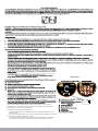
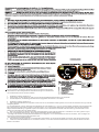
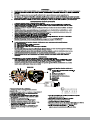
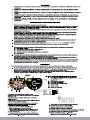
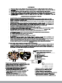
HOW TO USE
Follow Step 1 to Step 2 to use this equipment.
Step 1 : Connect the anchorage eye of Retractable Block to a suitable anchorage point situated either above the user's head or in horizontal
direction using karabiners (EN 362) & Ensure karabiner is locked.
Step 2: Now Connect the hook at attachment end of Retractable to the dorsal attachment of your full body harness. User is now safe to
move in normal speed.
* This Block can also
be used in horizontal
direction.
In the event of a fall, Retractable block locks and also minimizes the impact forces on the body of user, both in vertical and horizontal direction.
8 023577 034492

WARNING :
1. Ensure the medical condition of the user does not affect his safety in normal and emergency use.
2. The Retractable Fall Arrester shall only be used by a person trained and competent in its safe use.
3. A rescue plan shall be in place to deal with any emergencies that could arise during the work.
4. Do not make any alterations or additions to the Retractable Fall Arrester without the manufacturer’s prior written consent and that any repair shall only be carried out by
personnel trained by the manufacturer & duly authorized by him.
5. The Retractable Fall Arrester shall not be used out side its limitation, or for any purpose other than that for which it is intended.
ADVICE & INFORMATION :
- The Retractable Fall Arrester should be the personnel property of the user.
- Ensure that the Retractable Fall Arrester is compatible with other items when assembled into a system.
- Usage with other un-compatible items may be dangerous & hazardous as the safe function of one item may be affected or interferes with the safe function of another.
- The user should carry out a pre-use check of the Retractable Fall Arrester, to ensure that it is in a serviceable condition and operates correctly before it is used.
- The pre-use check shall involve checking of any wear or abrasion on wire ropes/webbing and sign of corrosion if any on metal parts or any breakage of the casing.
- Withdraw from use immediately if there is any doubt about its safe condition or if it has already arrested a fall, the equipment shall not be used again until conrmed in
writing by a competent person that it is acceptable to do so.
- Ensure that the strength of the anchor device is greater than 12kN.
- Use karabiner conforming to EN 362 for connecting to the anchor points.
- It is advisable to use the dorsal attachment D-Ring of the harness for connection to the Retractable Fall Arrester.
- However if it is not possible for any reason, the chest attachment element may also be used.
- It is essential to verify that a minimum 4m height of free space is available below the user's feet & the ground level at the work place, so that in case of a fall, there will be
no collision with the ground or other obstacle in the fall path.
- Following conditions may be hazardous & may affect the performance of Retractable Fall Arrester:-
(a) Extreme temperature
(b) Trailing or looping of Lanyards over sharp edges.
(c) Extreme acidic or basic environments.
(d) Abrasive or sharp edge structures which can damage the equipment.
(e) Pendulum falls.
- Ensure that manufacturer’s packing is used during transportation to prevent damage. In case original packing in not available, use polybag which is sealed to prevent
moisture.
- If used properly, the Retractable Fall Arrester has a life of 10 years from the date of manufacture unless subjected to severe abrasions or extreme temperatures condition.
- It is essential for the safety of the user that if the product is resold outside the original country of destination, the reseller shall provide instruction for use, for maintenance,
for periodic examination and for repair in the language of the country is which product in to be used.
-
I. Additional information as per VG 11
a. It is possible to use a horizontal retractable type fall arrester over an edge type A
b. It is recommended to avoid the loading of the retractable type fall arrester over edges.
II. Additional information as per VG 11
a. The retractable type fall arrester was tested also for horizontal use and a drop over a Type A edge has been successfully tested.
Type A edge denition: A steel edge with a radius of r = 0.5 mm and without burrs was used for the test. Due to this test, the equipment may be used over similar edges, as can be
found e.g. at rolled steel proles, at wooden beams or at a clad, rounded roof parapet. However, the following shall be considered when the equipment is used in a horizontal or
transverse arrangement and a risk of a fall from a height over an edge exists:
1. If the risk assessment carried out before the start of the work shows that the edge is very “cutting” and / or “free of burrs” (such as in case of an unclad roof parapet, a rusty steel girder
or a concrete edge)
- relevant measures shall be taken before the start of the work to prevent a drop over the edge or, before the start of work, an edge protection shall be mounted or
- the manufacturer shall be contacted.
2. The anchor point should only be situated at the same height as the edge at which a fall might occur or above the edge.
3. Allow adequate clearance of minimum 4 meters below, in order to avoid collision with the adjacent structures or the ground in the event of a fall.
4. To attenuate a drop ending in a pendulum movement, the working area or lateral movements to both sides of the centre axis shall be limited to a maximum of 1.50 m. In other cases, no
individual anchor points, but, e.g., type C or type D anchor devices in accordance with EN 795:2012 shall be used.
a. The Retractable Fall Arrester Block can also be used with Type C anchor device.
b. The deection of the anchor device shall be taken into account when determining the clearance required below the feet of the user. To that effect, the indications specied in the
instructions for use of the anchor device shall be considered.
c. Care must be taken to avoid collision with any obstruction in the event of a fall.
d. It is advised that, for the event of a fall over the edge, special pre-planned rescue measures must be taken under the guidance of a well-trained and competent personnel.
This is advised that Annual inspection should be done by competent person & if found any discrepancy in product service will be done at authorized service center only.
2
INSTRUCTION FOR MAINTENANCE :
- Follow the maintenance instructions procedure laid below strictly.
- In case of minor soiling, wipe the equipment with cotton cloth or soft brush. Do not use any abrasive material. For intensive cleaning wash in water at a temperature
00
between 25 C to 50 C using a neutral detergent. It should be allowed to dry by itself and be kept away from open re or any other source of heat, Avoid direct sunlight.
- Store in cool dry place, preferably away from moisture, direct sunlight, extra acidic or basic conditions & sharp edges.
LIFESPAN: The estimated product Lifespan is 10 years from the date of manufacturing. The following factors can reduce the Lifespan of the product : intense use, contact
with chemical substances, specially aggressive environment, extreme temperature exposure, UV exposure, abrasion, cuts, violent impacts, bad use or maintenance.

OK
100 Kg max
100 kg max
EN 360:2002
EN 360:2002
retractable
fall arrester block
(sharp edge protection)
PRODUCT REF. NO. : 225020100KK
WIRE ROPE LENGTH : SAMPLE
BATCH NO. : SAMPLE
SERIAL NO. : SAMPLE
MONTH & YR OF MFR. : XX/YYYY
DISCLAIMERS:- This information on the product is based upon technical data that Kong obtained under laboratory conditions and believes to be reliable. Kong does not
guarantee results and take no liability or obligation in connection with this information. As conditions of end use are beyond our control it is the user's responsibility to
determine the hazard levels and the use of proper personal protective equipment. Persons having technical expertise should undertake evaluation under their own specic
end-use conditions, at their own discretion and risk. Please ensure that this information is only used to check that the product selected is suitable for the intended use. Any
product that is damaged, torn worn or punctured should be discontinued from usage immediately.
(ii)
EQUIPMENT RECORD
Product
:
Model & type/Identication
Trade Name
Identication number
Manufacturer Address
Tel, fax, email into use
Year of manufacture Purchase Date Date rst put into use
Other relevant information (e.g. document number)
PERIODIC EXAMINATION AND REPAIR HISTORY
Date
Defects noted, repairs Name and signature
Periodic examination
of competent person
next due date
Reason for entry
(periodic examination
or repair)
relevant information
carried out and other
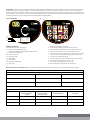
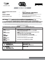
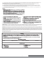
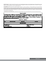
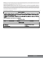
MARKING EXPLANATION
The Retractable Fall Arrester is marked with:
(i) The CE mark showing that the product
meets the requirements of the PPE Regulation (EU) 2016/425
(ii) Identication of manufactures
(iii) Type or product code
(iv) Wire/ Rope Length
(v) Batch Number
(vi) Serial Number
(vii) Month/Year of Manufacture
(viii) Norm & Year
1. Keep away from sunlight or heavy rains.
2. Ensure that the anchorage point has strength of min 12kN.
0
3. Ensure that the max angle between the vertical & the lanyard is 40.
4. Ensure that wire rope has no cuts or abrasion marks before use.
5. Once the wire rope has been reeled out, do not leave it suddenly to retract
inside on its own, let it go inside gradually by guiding it slowly inside.
6. Can be used for horizontal applications.
7. Connect the lanyard to the Dorsal attachment element of your harness.
0 0
8. Use between temperature range of -30 C to + 50 C.
9. To be used by person weighing upto than 100 kgs.
10. Do not attempt repair unless trained by the manufacturer.
Label of 225020100KK
(iii) (iv)
(v) (vi)
(vii) (viii)
(I)
3
DECLARATION OF CONFORMITY (EU) : You are free to download the declaration of conformity on our website www.kong.it/conformity

Test per EN 360:2002 Esito / Commento
8 023577 034492
1
ha sostenuto 15kN per 3 minuti senza rilascio (SUPERATO)
Quando testato con una massa di 100 kg
225020100KK
SATRA Technology Europe Ltd, Bracetown Business Park, Clonee,
Dublin D15 YN2P Ireland (organismo noticato 2777)
Nota : Si invita l’utilizzatore a conservare il presente manuale d’uso per tutta la durata di vita del prodotto.
EN 360:2002
&
VG11 RFU # 11.060
dal regolamento europeo
(UE) 2016/425 tale regolamento
& VG11RFU#11.060
≤
SGS Fimko Oy, P.O. Box 30 (Särkiniementie 3), 00211 HELSINKI,
Finland (Notified Body 0598)

OK
100 Kg max
100 kg max
EN 360:2002
EN 360:2002
retractable
fall arrester block
(sharp edge protection)
MARCATURE
Le marcature del Dispositivo Anticaduta
Retrattile sono le seguenti:
(I) marcatura CE a dimostrazione della
conformità con i requisiti contenuti del
Regolamento 2016/425 sui DPI;
(ii) Identificazione del fabbricante;
(v) numero partita;
(vi) numero di serie;;
(iv) lunghezza della linea;
(iii) tipo o codice del prodotto a
dimostrazione della conformità ai
requisiti dell'Art.8 della direttiva94/9/EC;
(vii) mese/anno di fabbricazione:
(iii)
(iv)
(v) (vi)
(vii)
PRODUCT REF. NO.
WEBBING LENGTH
BATCH NO.
SERIAL NO.
MONTH & YR OF MFR.
:
:
:
:
:
XX MS.
XXXXX
XXXXX
XX/XXXX
2
o
40max
COME SI USA
collegare il connetore del dispositivo anticaduta retrattile, posto all'estremita della linea, all'elemento di attaco dell'imbracatura completa e accertarsi che sia
chiuso.
sotto i piedi dell'utente
Si consiglia di eseguire un'ispezione annuale da parte di una persona competente
e, se riscontrata, qualsiasi discrepanza nel servizio del prodotto verrà effettuata
solo presso il centro di assistenza autorizzato.
II. Informazioni aggiuntive secondo VG 11
Definizione del bordo di tipo A: per il test è stato utilizzato un bordo in acciaio con un raggio di r = 0,5 mm e senza bave. A causa di questo test,
l'apparecchiatura può essere utilizzata su bordi simili, come si può trovare ad es. con profili in acciaio laminato, con travi in legno o con un parapetto
arrotondato. Tuttavia, quando l'apparecchiatura viene utilizzata in una disposizione orizzontale o trasversale e si verifica un rischio di caduta da un'altezza
al di sopra di un bordo, è necessario considerare quanto segue:
I. Informazioni aggiuntive secondo VG 11
a. Il dispositivo anticaduta retrattile è stato testato anche per uso orizzontale e una caduta su un bordo di tipo A è stata testata con successo.
a. È possibile utilizzare un dispositivo anticaduta retrattile orizzontale su un bordo di tipo A
b. si raccomanda di evitare il caricamento del dispositivo anticaduta retrattile sopra i bordi.

SCHEDA DISPOSITIVO
Identificazione Modello e tipo
Fabbricante
Anno di fabbricazione/durata di vita
Nome commerciale
Indirizzo
Data di acquisto
Numero identificativo del dispositivo
Tel, fax, email, sito web
Data primo utilizzo
Altre informazioni rilevanti (es. numero di documento)
REVISIONE PERIODICA E RIPARAZIONI
3
DURATA DI VITA: la durata di vita stimata del prodotto è di 10 anni dalla data di produzione. I seguenti fattori possono ridurre la durata di vita: uso intenso,
contatto con sostanze chimiche, ambienti particolarmente aggressivi, esposizione a temperature estreme, esposizione a raggi UV, abrasioni, tagli, impatti
violenti, uso errato, errata manutenzione.
ATTENZIONE: Queste informazioni sul prodotto si basano su dati tecnici ottenuti in laboratorio, ricavati da KONG e da essa ritenuti attendibili. KONG non
garantisce risultati e non prende responsabilità o obblighi connessi a queste informazioni. In quanto le condizioni di utilizzo sono oltre al nostro controllo, è
responsabilità dell’utilizzatore individuare i rischi e determinare gli adatti DPI da impiegare. Personale tecnico esperto deve procedere alla valutazione nelle
condizioni specifiche di utilizzo, a loro discrezione e rischio. Verificare che queste informazioni siano utilizzate solo per controllare che il dispositivo si adatto per
l’uso previsto. Qualsiasi prodotto danneggiato, usurato, strappato, o perforato deve essere rimosso dall’uso immediatamente.
- le misure pertinenti devono essere prese prima dell'inizio dei lavori per evitare una caduta oltre il bordo o, prima dell'inizio dei lavori, deve essere montata
una protezione dei bordi o
1. Se la valutazione del rischio effettuata prima dell'inizio dei lavori mostra che il bordo è molto "tagliente" e / o "privo di sbavature" (come nel caso di un
parapetto sul tetto non appiattito, una trave di acciaio arrugginita o un bordo di cemento )
- il produttore deve essere contattato.
2. Il punto di ancoraggio deve essere alla stessa altezza del bordo in cui potrebbe verificarsi una caduta o sopra il bordo.
3. Lasciare uno spazio adeguato di almeno 4 metri sotto, al fine di evitare la collisione con le strutture adiacenti o il terreno in caso di caduta.
4. Per alleviare una caduta che termina con un movimento a pendolo, l'area di lavoro oi movimenti laterali su entrambi i lati dell'asse centrale devono essere
limitati a un massimo di 1,50 m. In altri casi, non devono essere usati punti di ancoraggio individuali, ma devono essere utilizzati, ad esempio, ancore di tipo C o
D di tipo conforme alla norma EN 795: 2012.
a. Il blocco anticaduta retrattile può essere utilizzato anche con il dispositivo di ancoraggio di tipo C.
b. La deflessione del dispositivo di ancoraggio deve essere presa in considerazione per determinare il gioco richiesto sotto i piedi dell'utente. A tal fine,
devono essere prese in considerazione le indicazioni specificate nelle istruzioni per l'uso del dispositivo di ancoraggio.
c. Si deve prestare attenzione per evitare la collisione con qualsiasi ostacolo in caso di caduta.
d. Si consiglia che, in caso di una caduta oltre il limite, si debbano prendere speciali misure di soccorso pre-programmate sotto la guida di un personale ben
addestrato e competente.
DICHIARAZIONE DI CONFORMITÀ (UE): La dichiarazione di conformità (UE) può essere scaricata gratuitamente sul sito Internet www.kong.it/conformity

8 023577 034492
225020100KK
SATRA Technology Europe Ltd, Bracetown Business Park, Clonee,
Dublin D15 YN2P Ireland (Organismo noticado 2777)
la Reglamentación
europea 2016/425 dicha Reglamentación
Nota : Se recomienda que el usuario conserve este manual de instrucciones durante la vida útil del producto.
EN 360:2002
&
VG11 RFU # 11.060
Cuando se prueba con una masa de
Ha sostenido 15kN durante 3 minutos sin ceder (APPROBADO)
1
& VG11RFU#11.060 y
≤
SGS Fimko Oy, P.O. Box 30 (Särkiniementie 3), 00211 HELSINKI,
Finland (Notified Body 0598)

OK
100 Kg max
100 kg max
EN 360:2002
EN 360:2002
retractable
fall arrester block
(sharp edge protection)
MARCAS
Las marcas del dispositivo anticaída
retráctil son las siguientes:
(I) marca CE como demostración de la
conformidad con los requisitos contenidos
en la Reglamentación europea 2016/425
sobre los EPI;
(ii) identificación del fabricante;
(iii) tipo o código del producto;
(iv) longitud del cable metálico/cordón;
(v) número de lote;
(vi) número de serie; mes/año de fabricación;
(iii)
(iv)
(v) (vi)
(vii)
PRODUCT REF. NO.
WEBBING LENGTH
BATCH NO.
SERIAL NO.
MONTH & YR OF MFR.
:
:
:
:
:
XX MS.
XXXXX
XXXXX
XX/XXXX
o
40max
CÓMO SE USA
2
connectar ahora el gancho al elemento de fijacion del arnes completo y asegurarse de que quede bloqueado.
debajo de los pies
del usuario
Se recomienda que la inspección anual sea realizada por una persona competente
y, si se encuentra, cualquier discrepancia en el servicio del producto se realizará
en un centro de servicio autorizado.
b. Se recomienda evitar la carga del dispositivo de detención de caídas
Definición del borde Tipo A: Se usó un borde de acero de radio r = 0.5 mm y sin rebabas para la prueba. Con esta prueba, el equipo se puede
utilizar en bordes similares, como se puede encontrar por ejemplo. en perfiles de acero laminado, en vigas de madera o en un parapeto de techo
redondeado y enfundado. Sin embargo, se debe tener en cuenta lo siguiente cuando el equipo se utiliza en una disposición horizontal o transversal
y existe el riesgo de caerse sobre un borde:
I. Información adicional según VG 11
a. Es posible utilizar un dispositivo retráctil horizontal en un borde tipo A
de tipo retráctil sobre los bordes.
a. El dispositivo anticaídas de tipo retráctil también se probó para uso horizontal y una caída sobre un borde Tipo A se probó con éxito.
II. Información adicional según VG 11

Fecha Daño observado Reparación Comentarios
IDENTIFICACIÓN
1. No exponer a los rayos solares o a fuertes lluvias.
2. Asegurarse de que el punto de anclaje tenga una resistencia mínima de 12 KN.
3. Asegurarse de que el ángulo máximo entre la vertical y el lanyard sea de 40º.
4. Antes del uso, asegurarse de que el cable metálico/cordón no presente cortes o señales de abrasión.
5. Una vez extraído el cable metálico/cordón, se debe volver a introducir, durante la retracción, de forma lenta y gradual.
6. Bloque retràctil tambièn puede utilizarse horizontalmente
7. Conectar el lanyard a la fijación dorsal del arnés.
8. Utilizar a temperaturas de entre 30°C y 50°C.
9. Sólo lo pueden utilizar personas de peso inferior a 100 kg.
10. No intentar realizar reparaciones si no se ha recibido la formación del fabricante.
11. Asegurarse de que cada vez que el cable metálico/cinta se extrae o se desenrolla sea en sentido vertical, sin inclinaciones.
EXENCIÓN DE RESPONSABILIDAD: Esta información sobre el producto se basa en los datos técnicos que KONG ha obtenido en condiciones de
laboratorio y cree que son fiables. KONG no garantiza los resultados y no asume ninguna responsabilidad u obligación en relación con esta información.
Dado que las condiciones de uso final están fuera de nuestro control, es responsabilidad del usuario determinar los niveles de peligro y el uso del equipo
de protección individual adecuado. Las personas con experiencia técnica deben realizar una evaluación bajo sus propias condiciones específicas de uso
final, a su propia discreción y riesgo. Asegúrese de que esta información sólo se use para verificar que el producto seleccionado sea adecuado para el uso
previsto. Cualquier producto que esté dañado, rasgado, desgastado o pinchado debe ser retirado del uso inmediatamente.
VIDA UTIL: La vida útil de este producto es de 10 años a contar a partir de la fecha de fabricación. Los siguientes factores pueden reducir la vida útil: Uso
intensivo, contacto con substancias químicas, condiciones ambientales agresivas, exposición a temperaturas extremas, exposición a rayos UV, abrasión,
cortes, impactos violentos, mal uso o mantenimiento.
3
- se tomarán las medidas pertinentes antes del inicio del trabajo para evitar una caída sobre el borde o, antes del inicio del trabajo, se debe montar una
protección de borde o
1. Si la evaluación de riesgos realizada antes del inicio del trabajo muestra que el borde es muy "cortante" y / o está "libre de rebabas" (como en el caso de
un parapeto sin techo, una viga de acero oxidado o un borde de concreto) )
- Se deberá contactar al fabricante.
4. Para aliviar una caída que termina en un movimiento de péndulo, el área de trabajo o los movimientos laterales en ambos lados del eje central se
limitarán a un máximo de 1,50 m. En otros casos, no se utilizarán puntos de anclaje individuales, pero, por ejemplo, anclajes de tipo C o tipo D de acuerdo
con EN 795: 2012.
c. Se debe tener cuidado para evitar colisiones con cualquier obstrucción en caso de una caída.
d. Se recomienda que, en el caso de una caída sobre el borde, se deban tomar medidas especiales de rescate preplanificadas bajo la guía de un
personal bien capacitado y competente.
3. Dejo un espacio libre de al menos 4 metros por debajo para evitar colisiones con estructuras adyacentes o el suelo en caso de una caída.
a. El bloque retráctil de detención de caídas también se puede usar con un anclaje tipo C.
b. La deflexión del dispositivo de anclaje se tendrá en cuenta al determinar el espacio libre requerido debajo de los pies del usuario. A tal efecto, se
considerarán las indicaciones especificadas en las instrucciones de uso del dispositivo de anclaje.
2. El punto de anclaje solo debe estar a la misma altura que el borde en el que podría ocurrir una caída o por encima del borde.
DECLARACIÓN DE CONFORMIDAD (UE): La Declaración de Conformidad (UE) se puede descargar libremente en nuestro sitio de internet www.kong.it/conformity

Essai pour EN 360:2002 Résultat/ Commentaires
8 023577 034492
225020100KK
SATRA Technology Europe Ltd, Bracetown Business Park, Clonee,
Dublin D15 YN2P Ireland (Organisme notié 2777)
le Règlement (UE) 2016/425
ce règlement
Note : L'utilisateur est invité à conserver le manuel d'instructions tout au long de la vie du produit
EN 360:2002
&
VG11 RFU # 11.060
1
La longe a soutenu 15kN pendant 3 minutes sans relâchement (sangle) (passé)
Lorsque testé avec une masse de 100kg
& VG11RFU#11.060
≤
SGS Fimko Oy, P.O. Box 30 (Särkiniementie 3), 00211 HELSINKI,
Finland (Notified Body 0598)

OK
100 Kg max
100 kg max
EN 360:2002
EN 360:2002
retractable
fall arrester block
(sharp edge protection)
MARQUAGES
(iii)
(iv)
(v)
(vi)
(vii)
PRODUCT REF. NO.
WEBBING LENGTH
BATCH NO.
SERIAL NO.
MONTH & YR OF MFR.
:
:
:
:
:
XX MS.
XXXXX
XXXXX
XX/XXXX
o
40max
COMMENT L'UTILISER
2
le Règlement
(UE) 2016/425
connecter ensuite le crochet de l'extrêmité de l'antichute rétractable au point d'attache dorsal du harnais complet.
sous les pieds
de l'utilisateur
Il est recommandé que l'inspection annuelle soit effectuée par une personne
compétente et, le cas échéant, toute anomalie dans l'utilisation du produit sera
effectuée dans un centre de service agréé.
I. Informations complémentaires selon VG 11
b. Il est recommandé d'éviter de charger les antichutes rétractables sur les arêtes.
a. Le dispositif antichute rétractable a également été testé pour une utilisation
horizontale et une chute sur une arête de type A a été testée avec succès.
II. Informations complémentaires selon VG 11
a. Il est possible d'utiliser un dispositif antichute rétractable horizontal sur une
arête de type A

IDENTIFICATION
1 Ne jamais exposer aux rayons du soleil ou à de fortes pluies.
2. S'assurer que le point d'ancrage ait une résistance de 12 kN au moins.
3. S'assurer que l'angle maximal entre la verticale et la longe soit de 40°.
4. Avant l'emploi, s'assurer que le câble en métal/sangle ne présente pas de marques de coupure ou d'abrasion.
5. Une fois le câble métallique/sangle sorti, lors de la rétraction, il faut le réaccompagner à l'intérieur, lentement et graduellement.
6. Les bloqueurs rétractables peuvent être utilisés dans le sens horizontal aussi.
7. Connecter la longe à l'attache dorsale du harnais.
8. Peut être utilisé à des températures comprises entre 30°C et 50°C.
9. Peut être utilisé seulement par des personnes ayant un poids inférieur à 100 kg.
10. Ne jamais essayer d'exécuter des réparations, à moins de n'avoir été instruits par le fabricant.
11. Chaque fois que le câble en métal/sangle est sorti ou déroulé, s'assurer que ceci advienne dans le sens vertical sans se fléchir.
3
DUREE DE VIE : la durée de vie estimée du produit est de 10 ans à compter de la date de fabrication. Les facteurs suivants peuvent réduire la durée de
vie du produit: utilisation intense, contact avec des substances chimiques, environnement particulièrement agressif, exposition à des températures
extrêmes, exposition aux UV, abrasion, coupures, impacts violents, mauvais usage ou entretien.
ATTENTION : ces informations sur le produit sont basées sur les données techniques que KONG a obtenues dans des conditions de laboratoire et qui
sont considérées comme fiables. KONG ne garantit pas les résultats et n'assume aucune responsabilité quant à ces informations. Étant donné que les
conditions d’utilisation finales sont indépendantes de notre volonté, il incombe à l’utilisateur de déterminer les niveaux de danger et d’utiliser un
équipement de protection individuelle approprié. Les personnes ayant des connaissances techniques devraient entreprendre une évaluation dans
leurs propres conditions d'utilisation finale, à leur propre discrétion et à leurs propres risques. Assurez-vous que ces informations servent uniquement à
vérifier que le produit sélectionné est adapté à l'utilisation envisagée. Tout produit endommagé, déchiré, usé ou perforé doit être immédiatement arrêté.
d'un personnel bien formé et compétent.
c. Il faut veiller à éviter toute collision avec une obstruction en cas de chute.
d. Il est conseillé que, en cas de chute par-dessus bord, des mesures de sauvetage spéciales planifiées à l'avance soient prises sous la supervision
doivent être limités à 1,50 m au maximum. Dans d'autres cas, aucun point d'ancrage individuel, mais, par exemple, des dispositifs d'ancrage d e type
C ou de type D conformément à l'EN 795: 2012 doivent être utilisés.
b. Le fléchissement du dispositif d'ancrage doit être pris en compte lors de la détermination du dégagement requis sous les pieds de l'utilisateur. À cet
a. Le bloc antichute rétractable peut également être utilisé avec un dispositif d'ancrage de type C.
effet, les indications spécifiées dans les instructions d'utilisation du dispositif d'ancrage doivent être prises en compte.
- des mesures appropriées doivent être prises avant le début des travaux pour empêcher toute chute par-dessus le bord ou, avant le début des
travaux, une protection du bord doit être montée ou
2. Le point d'ancrage ne devrait être situé qu'à la même hauteur que le bord auquel une chute pourrait se produire ou au-dessus du bord.
- le fabricant doit être contacté.
3. Laisser un dégagement suffisant d'au moins 4 mètres dessous afin d'éviter toute collision avec les structures adjacentes ou le sol en cas de chute.
4. Pour atténuer une chute se terminant par un mouvement pendulaire, la zone de travail ou les mouvements latéraux des deux côtés de l'axe c entral
1. Si l'évaluation des risques effectuée avant le début des travaux montre que le bord est très «coupant» et / ou «exempt de bavures» (comme dans
le cas d'un parapet de toit non revêtu, d'une poutre en acier rouillé ou d'un bord en béton), )
Définition de bord de type A : Un bord en acier de rayon r = 0,5 mm et sans bavure a été utilisé pour l'essai. Grâce à ce test, l'équipement peut être
utilisé sur des bords similaires, comme on peut le trouver par exemple. sur des profils en acier laminés, sur des poutres en bois ou sur un parapet de toit
arrondi et gainé. Toutefois, les éléments suivants doivent être pris en compte lorsque l'équipement est utilisé selon une disposition horizontale ou
transversale et qu'il existe un risque de chute de hauteur par-dessus un bord:
DÉCLARATION DE CONFORMITÉ (UE): La déclaration de conformité (UE) peut être téléchargée librement sur notre site Internet www.kong.it/conformity

Anwendbar bei ausziehbaren Absturzsicherungssystemen : 225020100KK
Verteiler : KONG SPA. VIA XXV APRILE, 4 (ZONA INDUSTRIALE)
I - 23804 MONTE MARENZO (LC) ITALY
Zertifizierungsstelle : SATRA Technology Europe Ltd, Bracetown Business Park, Clonee,
Benannte StelleDublin D15 YN2P Ireland ( 2777)
Kontinuierliche Prüfstelle : SGS Fimko Oy, P.O. Box 30 (Särkiniementie 3), 00211 HELSINKI,
Finland (Notified Body 0598)
Punkt 4.2
Statische Belastbarkeit
(EN 364:1993)
Punkt 4.1
Konzeption und Ergonomie
Materialien und Aufbau
Punkt 4.4
(EN 364:1993)
Punkt 4.5
Dynamische Leistungen
Punkt 4.7
Korrosionsfestigkeit
(EN 364:1993)
Das Verbindungsmittel erfüllt die Anforderung der statischen Belastbarkeit (BESTANDEN).
Fehlen sperriger Teile (BESTANDEN).
hat 12kN 3 Minuten ausgehalten ohne Nachgeben (BESTANDEN).hat 15kN 3 Minuten
ausgehalten ohne Nachgeben (BESTANDEN)
Bremskraft von <6,0kN, Auffangabstand von <2m (BESTANDEN).
Test ausgeführt nach Norm ISO 9227:1990, 24 Stunden (BESTANDEN).
Fehlen scharfer oder zu stark scheuernder Oberflächen auf dem Verbindungsmittel (BESTANDEN).
Garantiert die Leistungen lt. EN 360:2002 (BESTANDEN).
Am Ende des Verbindungsmittels befindet sich eine Öse zur Befestigung an dem Gurt und am
Absturzsicherungssystem (BESTANDEN).
Wenn mit der Testmasse von 100 KG
Test für EN 360:2002 Ausgang/Kommentar
o
40max
VERWENDUNG
8 023577 034492
PSA-Verordnung
(EU) 2016/425 dieser Verordnung
1
Hinweis : Dem Benutzer wird empfohlen, diese Betriebsanleitung während der gesamten Lebensdauer des Produkts aufzubewahren.
EN 360:2002
&
VG11 RFU # 11.060
& VG11RFU#11.060
≤

OK
100 Kg max
100 kg max
retractable
fall arrester block
(sharp edge protection)
2
der Verordnung (UE)
2016/425
unter den Füßen des Benutzers
Es wird empfohlen, die jährliche Überprüfung durch eine sachkundige Person
durchzuführen & Wenn festgestellt wird, dass Abweichungen im Produktservice
nur bei autorisierten Service-Centern auftreten.
I. Zusätzliche Angaben gemäß VG 11
a. Es ist möglich, an einer Kante des Typs A eine horizontal einziehbare Absturzsicherung zu verwenden
b. Es wird empfohlen, die Belastung des Höhensicherungsgerätes über Kanten zu vermeiden.
II. Zusätzliche Angaben gemäß VG 11
1. Wenn die vor Beginn der Arbeiten durchgeführte Risikobewertung ergibt, dass die Kante sehr "schneidend" und / oder "gratfrei" ist (z. B.
bei einer unverkleideten Dachbrüstung, einem rostigen Stahlträger oder einer Betonkante) )
a. Das einziehbare Absturzsicherungssystem wurde auch für den horizontalen Einsatz getestet, und ein Fall auf eine Kante des Typs A wurde
erfolgreich getestet.
2. Der Verankerungspunkt sollte sich nur auf derselben Höhe befinden, an der die Kante gefallen sein könnte, oder über der Kante liegen.
Typ A Kantendefinition: Für den Test wurde eine Stahlkante mit einem Radius von r = 0,5 mm und ohne Grate verwendet. Aufgrund dieses Tests
kann die Ausrüstung über ähnlichen Kanten verwendet werden, wie z. bei gewalzten Stahlprofilen, bei Holzbalken oder bei einer plattierten,
abgerundeten Dachbrüstung. Folgendes ist jedoch zu beachten, wenn das Gerät in horizontaler oder Querrichtung verwendet wird und ein
Absturz von einer Höhe über eine Kante besteht:
- Der Hersteller muss kontaktiert werden.
- Vor Beginn der Arbeiten sind entsprechende Maßnahmen zu ergreifen, um ein Herunterfallen der Kante zu verhindern, oder vor Beginn der
Arbeit muss ein Kantenschutz angebracht werden oder
3. Lassen Sie einen Mindestabstand von mindestens 4 Metern, um im Falle eines Sturzes Kollisionen mit benachbarten Bauten oder dem
Boden zu vermeiden.
EN 360:2002
EN 360:2002

3
ACHTUNG: Diese Information über das Produkt basiert auf technischen Daten, die KONG unter Laborbedingungen erhalten hat und für zuverlässig hält.
KONG garantiert keine Ergebnisse und übernimmt keine Haftung oder Verpflichtung in Verbindung mit diesen Informationen. Da die Bedingungen für den
Endgebrauch außerhalb unserer Kontrolle liegen, ist der Benutzer dafür verantwortlich, die Gefahrenstufen und die Verwendung geeigneter persönlicher
Schutzausrüstung zu bestimmen. Personen mit technischen Kenntnissen sollten nach eigenem Ermessen und Risiko eine Bewertung unter ihren eigenen
spezifischen Endbenutzungsbedingungen vornehmen. Bitte stellen Sie sicher, dass diese Informationen nur verwendet werden, um zu prüfen, ob das
ausgewählte Produkt für den beabsichtigten Gebrauch geeignet ist. Jedes Produkt, das beschädigt, abgerissen oder durchstochen ist, sollte sofort
außer Betrieb genommen werden.
LEBENSDAUER: Die geschätzte Produktlebensdauer beträgt 10 Jahre ab Herstellungsdatum. Die folgenden Faktoren können die Lebensdauer des
Produkts verringern: intensive Verwendung, Kontakt mit chemischen Substanzen, aggressive Umgebung, dauerhafte UV-Einwirkung, extreme
Temperaturbelastung, Abrieb, Schnittverletzungen, gewaltsame Einwirkungen, nicht sach- und fachgerechte Verwendung oder Wartung.
d. Es wird empfohlen, dass im Falle eines Sturzes über Bord spezielle geplante Rettungsmaßnahmen unter Aufsicht von gut ausgebildetem und
kompetentem Personal durchgeführt werden.
c. Es ist darauf zu achten, dass bei einem Sturz keine Kollision mit einem Hindernis auftritt.
4. Um einen Sturz zu mildern, der in einer Pendelbewegung endet, darf der Arbeitsbereich oder die seitlichen Bewegungen auf beiden Seiten der
Mittelachse auf maximal 1,50 m begrenzt sein. In anderen Fällen dürfen keine einzelnen Verankerungspunkte verwendet werden, sondern
beispielsweise Anker vom Typ C oder Typ D gemäß EN 795: 2012.
b. Die Durchbiegung der Verankerungsvorrichtung muss bei der Bestimmung des erforderlichen Abstandes unter den Füßen des Benutzers
berücksichtigt werden. Zu diesem Zweck sind die in der Gebrauchsanweisung der Verankerungsvorrichtung angegebenen Angaben zu beachten.
a. Der einziehbare Höhensicherungsblock kann auch mit einer Verankerungsvorrichtung vom Typ C verwendet werden.
KONFORMITÄTSERKLÄRUNG (EU): Die Konformitätserklärung (EU) kann auf unserer Website www.kong.it/conformity

225010150KK, 225010200KK
I - 23804 MONTE MARENZO (LC) ITALY
ADVICE & INFORMATION :
- The Retractable Fall Arrester should be the personnel property of the user.
- Ensure that the Retractable Fall Arrester is compatible with other items when assembled into a system.
- Usage with other un-compatible items may be dangerous & hazardous as the safe function of one item may be affected or interferes with the safe function of another.
Applicable to :
KONG SPA. VIA XXV APRILE, 4 (ZONA INDUSTRIALE)
Manufacturer :
Certication Body : SATRA Technology Europe Ltd, Bracetown Business Park, Clonee,
Dublin D15 YN2P Ireland (Notied Body 2777)
Ongoing Assessment Body : SGS Fimko Oy, P.O. Box 30 (Särkiniementie 3), 00211 HELSINKI, Finland (Notied Body 0598)
The Retractable Fall Arrester is classed as a Personal Protective Equipment (PPE) by the European PPE Regulation (EU) 2016/425 and has shown to comply with this
Regulation through the Harmonized European Standard EN 360:2002.
CAREFULLY READ THESE INSTRUCTIONS BEFORE USING THIS RETRACTABLE FALL ARRESTER
This Retractable Fall Arrester is designed to minimise the risk of/provide protection against the danger of falling from heights. However, always remember that no item of PPE
can provide full protection and care must always be taken while carrying out the risk related activity.
PERFORMANCE AND LIMITATIONS OF USE
The equipment has been tested in accordance with EN 360:2002 and has achieved the following performance levels :
USER INSTRUCTION MANUAL
EN 360:2002
EN 360:2002 test Result/Comment
Clause 4.1
Design & Ergonomics
Clause 4.2
Materials & Construction
Clause 4.4
Static Strength
(EN 364:1993)
Clause 4.5
Dynamic Performance
(EN 364:1993)
Clause 4.7
Achieves required performance as stated in EN 360:2002 (PASS).
Lanyard free from sharp or excessively abrasive surface (PASS).
No unnecessary features which add signicantly to overall mass (PASS).
Lanyard end terminated with a loop, for connection to harness and fall arrest system (PASS).
Lanyard meets static strength requirment (PASS).
12kN sustained for 3 minutes without failure (Wire) (PASS).
15kN sustained for 3 minutes without failure (Webbing) (PASS).
When tested with the test mass of 140 kg,
The Arrest force <6.00 kN, Arrest distance <2.00 m (PASS).
Corrosion test in accordance with ISO 9227:1990-24 hours (PASS).
Corrosion Resistance
(EN 364:1993)
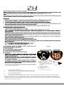
POSSIBLE USAGE:
This Retractable Fall Arrester can be used as a part of a fall arrest system or as a part of a restraint system. If using as a part of fall arrest system, a suitable anchor point (above
the user’s head, at least 12kN) shall be used. Attachments to the anchor points and other equipment shall be made using oval Karabiners to EN 362. The equipment is to be
used specically in vertical condition. Meterial of the lanyard -
- for wire rope block - 4.5mm dia Galvanized steel wire. - for webbing block - 25mm polyester textile webbing .
- for Textile rope block- 6mm dia technora rope
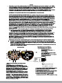
HOW TO USE :
STEP 1 : Connect the anchorage eye at the top of the Retractable Fall Arrester to a suitable anchorage point situated above the user’s head using Karabiners as per EN 362
& ensure the Karabiner is locked.
STEP 2 : Now connect the swivel hook of the equipment to the attachment element of your full body harness and ensure that it is locked. You are now safe to move up &
down in normal speed. In the event of a fall, the Retractable Fall Arrester locks & also minimises the impact forces on the body of user.
WARNING :
1. Ensure the medical condition of the user does not affect his safety in normal and emergency use.
2. The Retractable Fall Arrester shall only be used by a person trained and competent in its safe use.
3. A rescue plan shall be in place to deal with any emergencies that could arise during the work.
4. Do not make any alterations or additions to the Retractable Fall Arrester without the manufacturer’s prior written consent and that any repair shall only be carried out by
personnel trained by the manufacturer & duly authorized by him.
5. The Retractable Fall Arrester shall not be used out side its limitation, or for any purpose other than that for which it is intended.
Note: The user is advised to keep the user instructions document for the life of the product.
MNKG 07-04(EN)
- The user should carry out a pre-use check of the Retractable Fall Arrester, to ensure that it is in a serviceable condition and operates correctly before it is used.
- The pre-use check shall involve checking of any wear or abrasion on wire ropes/webbing and sign of corrosion if any on metal parts or any breakage of the casing.

1. Keep away from sunlight or heavy rains.
2. Ensure that the anchorage point has strength of min 12kN.
0
3. Ensure that the max angle between the vertical & the lanyard is 40.
4. Ensure that wire rope has no cuts or abrasion marks before use.
5. Once the wire rope has been reeled out, do not leave it suddenly to retract
inside on its own, let it go inside gradually by guiding it slowly inside.
6. Can be used for horizontal applications.
7. Connect the lanyard to the Dorsal attachment element of your harness.
0 0
8. Use between temperature range of -30 C to + 50 C.
9. To be used by person weighing upto than 140 kgs.
10. Do not attempt repair unless trained by the manufacturer.
EN 360:2002
140 Kg max
2 3
4
8
5
67
11
910
viii
1. Use of equipment in potentially explosive atmospheres
2. Group 2 system for surface use
3. System 2 category for high protection
4. Explosive atmosphere in gas form(hydrogen)
5. Protection by constructional safety (non-electric device)
6. Maximum surface temperature of the device 85°C
7. Equipment protection level: 1 -Explosive atmosphere present occasionally in normal use
- Withdraw from use immediately if there is any doubt about its safe condition or if it has
already arrested a fall, the equipment shall not be used again until conrmed in writing
by a competent person that it is acceptable to do so.
- Ensure that the strength of the anchor device is greater than 12kN.
- Use karabiner conforming to EN 362 for connecting to the anchor points.
- It is advisable to use the dorsal attachment D-Ring of the harness for connection to the
Retractable Fall Arrester.
- However if it is not possible for any reason, the chest attachment element may also be
used.
- It is essential to verify that a minimum 4m height of free space is available below the
user's feet & the ground level at the work place, so that in case of a fall, there will be no
collision with the ground or other obstacle in the fall path.
- User is advised to keep the User Instructions document for the life of product.
- Following conditions may be hazardous & may affect the performance of Retractable
Fall Arrester:-
(a) Extreme temperature
(b) Trailing or looping of Lanyards over sharp edges.
(c) Extreme acidic or basic environments.
(d) Abrasive or sharp edge structures which can damage the equipment.
(e) Pendulum falls.
- Ensure that manufacturer’s packing is used during transportation to prevent damage. In
case original packing in not available, use polybag which is sealed to prevent moisture.
- If used properly, the Retractable Fall Arrester has a life of 10 years from the date of
manufacture unless subjected to severe abrasions or extreme temperatures condition.
- It is essential for the safety of the user that if the product is resold outside the original
country of destination, the reseller shall provide instruction for use, for maintenance, for
periodic examination and for repair in the language of the country is which product in to
be used.
INSTRUCTION FOR MAINTENANCE :
- Follow the maintenance instructions procedure laid below strictly.
- In case of minor soiling, wipe the equipment with cotton cloth or soft brush. Do not use any abrasive material. For intensive cleaning wash in water at a temperature
0 0
between 25 C to 50 C using a neutral detergent. It should be allowed to dry by itself and be kept away from open re or any other source of heat, Avoid direct sunlight.
- Store in cool dry place, preferably away from moisture, direct sunlight, extra acidic or basic conditions & sharp edges.
LIFESPAN: The estimated product Lifespan is 10 years from the date of manufacturing. The following factors can reduce the Lifespan of the product : intense use, contact with
chemical substances, specially aggressive environment, extreme temperature exposure, UV exposure, abrasion, cuts, violent impacts, bad use or maintenance.
DISCLAIMERS:- This information on the product is based upon technical data that KONG obtained under laboratory conditions and believes to be reliable. KONG does not
guarantee results and take no liability or obligation in connection with this information. As conditions of end use are beyond our control it is the user's responsibility to
determine the hazard levels and the use of proper personal protective equipment. Persons having technical expertise should undertake evaluation under their own specic
end-use conditions, at their own discretion and risk. Please ensure that this information is only used to check that the product selected is suitable for the intended use. Any
product that is damaged, torn worn or punctured should be discontinued from usage immediately.
EQUIPMENT RECORD
Product
:
Model & type/Identication
Trade Name
Identication number
Manufacturer Address
Tel, fax, email into use
Year of manufacture Purchase Date
Date rst put into use
Other relevant information (e.g. document number)
PERIODIC EXAMINATION AND REPAIR HISTORY
Date
Defects noted, repairs Name and signature
Periodic examination
of competent person
next due date
Reason for entry
(periodic examination
or repair)
relevant information
carried out and other
( )iii
( )iv
( )v
( )vi
( )vii
225010200KK
MARKING EXPLANATION
PRODUCT REF. NO. :
WIRE ROPE LENGTH : SAMPLE
BATCH NO. : SAMPLE
SERIAL NO. : SAMPLE
MONTH & YR OF MFR. : XX/YYYY
The Retractable Fall Arrester is marked with:
(I) The CE mark showing that the
product meets the requirements
of the PPE Regulation (EU)
2016/425
(ii) Identication & address of manufacturer's
(iii) Type or product code
(iv) Wire/ Rope Length
(v) Batch Number
(vi) Serial Number
(vii) Month/Year of Manufacture
(viii) Norm & Year
(ix) Read the instruction before use
11. Ensure that whenever the wire rope/webbing is pulled/reeled out,
it should be vertically pulled it and not as an angle to the vertical.
DECLARATION OF CONFORMITY (EU) : You are free to download the declaration of conformity on our website www.kong.it/conformity

Ente di sorveglianza della prouzione
di classe III
12
diametro di 4,8 mm e da fettuccia in
225010150KK, 225010200KK
SATRA Technology Europe Ltd, Bracetown Business Park, Clonee,
Dublin D15 YN2P Ireland (Organismo Notificato 2777)
dal regolamento
europeo (UE) 2016/425 tale regolamento
Nota : Si invita l’utilizzatore a conservare il presente manuale d’uso per tutta la durata di vita del prodotto.
ha sostenuto 15kN per 3 minuti senza rilascio (SUPERATO)
Quando testato con una massa di 140 kg
MNKG 07-04(IT)
EN 360:2002
SGS Fimko Oy, P.O. Box 30 (Särkiniementie 3), 00211 HELSINKI,
Finland (Notified Body 0598)

m
12
7.
8.
9.
10.
11.
EN 360:2002
140 Kg max
225010150KK
2 3
4
8
5
67
11
910
sotto i piedi dell'utente
Si invita l’utilizzatore a conservare il presente manuale d’uso per tutta la durata di vita del prodotto.
del Regolamento 2016/425

ATTENZIONE: Queste informazioni sul prodotto si basano su dati tecnici ottenuti in laboratorio, ricavati da KONG e da essa ritenuti attendibili.
KONG non garantisce risultati e non prende responsabilità o obblighi connessi a queste informazioni. In quanto le condizioni di utilizzo sono oltre
al nostro controllo, è responsabilità dell’utilizzatore individuare i rischi e determinare gli adatti DPI da impiegare. Personale tecnico esperto deve
procedere alla valutazione nelle condizioni specifiche di utilizzo, a loro discrezione e rischio. Verificare che queste informazioni siano utilizzate
solo per controllare che il dispositivo si adatto per l’uso previsto. Qualsiasi prodotto danneggiato, usurato, strappato, o perforato deve essere
rimosso dall’uso immediatamente.
DURATA DI VITA: la durata di vita stimata del prodotto è di 10 anni dalla data di produzione. I seguenti fattori possono ridurre la durata di vita: uso
intenso, contatto con sostanze chimiche, ambienti particolarmente aggressivi, esposizione a temperature estreme, esposizione a raggi UV,
abrasioni, tagli, impatti violenti, uso errato, errata manutenzione.
MNKG 07-04(IT)
DICHIARAZIONE DI CONFORMITÀ (UE): La dichiarazione di conformità (UE) può essere scaricata gratuitamente sul sito Internet www.kong.it/conformity
La pagina si sta caricando...
La pagina si sta caricando...
La pagina si sta caricando...
La pagina si sta caricando...
La pagina si sta caricando...
La pagina si sta caricando...
La pagina si sta caricando...
La pagina si sta caricando...
La pagina si sta caricando...
-
 1
1
-
 2
2
-
 3
3
-
 4
4
-
 5
5
-
 6
6
-
 7
7
-
 8
8
-
 9
9
-
 10
10
-
 11
11
-
 12
12
-
 13
13
-
 14
14
-
 15
15
-
 16
16
-
 17
17
-
 18
18
-
 19
19
-
 20
20
-
 21
21
-
 22
22
-
 23
23
-
 24
24
-
 25
25
-
 26
26
-
 27
27
-
 28
28
-
 29
29


in altre lingue
- English: Kong RFA 10-15-20m User manual
- français: Kong RFA 10-15-20m Manuel utilisateur
- español: Kong RFA 10-15-20m Manual de usuario
- Deutsch: Kong RFA 10-15-20m Benutzerhandbuch
Documenti correlati


Altri documenti
-
Honeywell Miller MightEvac User Instruction Manual
-
 Metcal MFR-1300 Series Guida utente
-
POWERTEX HW Light Manuale utente
-
DuPont Tyvek® 500 HP Istruzioni per l'uso
-
-
Climbing Technology 2P656 Istruzioni per l'uso
-
MSA Latchways Self Reracting Lifeline Manuale utente
-
ISC UB066 Manuale utente
