

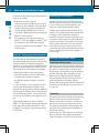
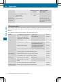
Symbols
G
WARNING
Warning notes make you aware of dangers
which could pose a threat to your health or
life, or to the health and life of others.
H
Environmental note
Environmental notes provide you with infor-
mation on environmentally aware actions or
disposal.
!
The
purpose of material damage warnings
is to draw your attention to risks which
could lead to damage to your engine sys-
tem.
i
These symbols indicate useful instruc-
tions or further information that could be
helpful to you.
X
This symbol designates an instruc-
tion you must follow.
X
Several consecutive symbols indi-
cate an instruction with several
steps.
(Y page)
This symbol tells you where you
can find further information on a
topic.
Y Y
This symbol indicates a warning or
an
instruction that is continued on
the next page.
Display
This text indicates an indicator in
the display.

Welcome
Familiarise yourself with your engine system
and read the operating instructions before
you
use the engine system. This will help you
to avoid endangering yourself or others.
The standard equipment and product descrip-
tion of your engine system may vary, depend-
ing on individual specifications. This is descri-
bed on the data card.
The engine systems are constantly updated
to be state of the art.
MTU/Mercedes-Benz reserves the right to
make changes to the following:
R
design
R
equipment
R
technical features
Descriptions may therefore differ in individual
cases from your engine system.
9345840981
É93458
40981-ËÍ

A
AdBlue
®
/DEF
Consumption ...................................
47
Gauge .............................................. 38
Important safety notes .................... 49
Refuelling ......................................... 49
Service product ............................... 57
ADM (FR (drive control) unit) ............. 12
B
Battery (vehicle)
Jump starting ...................................
69
Bleeding the fuel system
Bleeding the prefilter with a hand
pump ............................................... 67
Braking
Continuous brake ............................ 35
Engine brake .................................... 36
Retarder ........................................... 36
Buzzer ................................................... 47
C
Capacities ............................................
81
Care products ...................................... 59
Charge current .................................... 36
Checking the fluid level ...................... 32
Cleaning and care
Engine cleaning ................................ 59
High-pressure cleaning .................... 59
Notes on care .................................. 59
Consumption
AdBlue
®
/DEF .................................. 47
Fuel .................................................. 47
Oil (engine) ...................................... 47
Continuous brake
Important safety notes .................... 35
Coolant
Mixing ratio ...................................... 55
Service product ............................... 55
Topping up ....................................... 33
Coolant additive .................................. 55
Correct use ............................................ 7
Corrosion inhibitor/antifreeze
agent .................................................... 55
D
Data card ..............................................
78
DEF/AdBlue
®
see AdBlue
®
/DEF service products
Description of the engine ................... 12
Diagnostics connection ...................... 25
Diesel
Fuels ................................................ 56
Low outside temperatures ............... 56
Refuelling ......................................... 48
Dimensions .......................................... 79
Disposal of service products .............. 53
Driving mode
Idling speed ..................................... 36
Driving tips .......................................... 46
E
Electronic engine control
see Engine management
Electronic engine control unit ............
36
Emergency gearshift
Using the emergency switch ............ 37
Emergency running program ................ 7
Engine
Capacities ........................................ 81
Cleaning ........................................... 59
Data ................................................. 79
Data card ......................................... 78
Data plate ........................................ 78
Modifying the power output ............... 7
Oil consumption ............................... 47
Operating data ................................. 80
Rectifying faults ............................... 71
Running-in period ............................. 46
Starting ............................................ 34
Stopping .......................................... 35
Engine brake ........................................ 36
Engine data .......................................... 79
Engine data card .................................. 78
Engine description .............................. 12
Engine idling speed ............................. 36
Engine management ........................... 18
Engine oil
Consumption ................................... 47
For winter operation ........................ 53
Mixing .............................................. 54
2
Index

Oil change ........................................ 54
Topping up
....................................... 54
Engine overview .................................. 13
Engine speed ....................................... 37
Exhaust gas aftertreatment ............... 20
F
Fuel
Additives ..........................................
57
Consumption ................................... 47
Diesel ............................................... 56
Refuelling ......................................... 48
Fuel grade ............................................ 56
Fuel system
Automatic bleeding .......................... 67
Manual bleeding .............................. 67
Fuses
Checking and replacing a safety
fuse .................................................. 68
Important safety notes .................... 68
G
Gauge
AdBlue
®
/DEF
.................................. 38
Genuine Mercedes-Benz parts ............. 6
H
High-pressure cleaning ....................... 59
I
Identification plate ..............................
78
Idling speed
Engine .............................................. 36
Installation ........................................... 28
J
Jump-starting .......................................
69
M
Maintenance
Notes
............................................... 52
Mercedes-Benz Service Centre
see Qualified specialist workshop
O
Oil (engine)
For winter operation
........................ 53
Oil change ........................................ 54
Scope of use .................................... 54
Oil pressure ......................................... 37
Operating data ..................................... 80
Operating instructions
General notes .................................... 9
Operating safety .................................. 24
Operating safety and registration
Changes in engine performance ........ 7
Implied warranty ................................ 7
Operational monitoring ...................... 36
Organisational measures ................... 25
P
Personnel .............................................
25
Poly-V-belt
Replacing ......................................... 75
Routing ............................................ 75
Preparing for starting operation
see Starting operation
Protection of the environment ............. 6
Q
Qualified specialist workshop ..............
9
R
Refuelling
AdBlue
®
/DEF .................................. 49
Fuels ................................................ 48
Requirements of the personnel ......... 25
Rev counter .......................................... 37
Roadside Assistance ........................... 66
Running the vehicle in ........................ 46
S
Safety
and emergency running pro-
gram ....................................................... 7
Safety precautions .............................. 24
Service products
AdBlue
®
/DEF .................................. 57
Coolant ............................................ 55
Index
3

DEF/AdBlue
®
..................................
57
Diesel fuel ........................................ 56
Disposal ........................................... 53
Disposing of AdBlue
®
/DEF .............. 58
Engine oil ......................................... 53
Fuel additives ................................... 57
General notes .................................. 53
Purity of AdBlue
®
/DEF .................... 59
Storing AdBlue
®
/DEF ...................... 58
Specialist workshop .............................. 9
Starting
see Starting (engine)
Starting (engine) .................................. 34
Stopping and switching off the
engine ................................................... 34
T
Technical data
Dimensions ......................................
79
Filling capacities .............................. 81
Operating data ................................. 80
Weights ............................................ 79
Tightening torques .............................. 82
Transport .............................................. 28
W
Warning and indicator lamps
Electronics
....................................... 39
Engine, general ................................ 20
Warning buzzer .................................... 47
Weights ................................................ 79
Winter diesel ........................................ 56
Winter operation ................................. 50
4
Index

Engine system ....................................... 6
Protection of the environment ............. 6
Assembly equipment ............................ 6
Genuine Mercedes-Benz parts ............. 6
Modifying the engine output ................ 7
Safety/emergency running pro-
gram ....................................................... 7
Correct use ............................................ 7
Implied warranty ................................... 7
Stored data ............................................ 8
Qualified specialist workshop .............. 9
Further applicable documents ............. 9
5
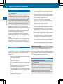
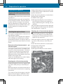
Introduction

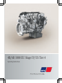
Engine system
The 4R 1000 and 6R 1000 series of engines
only function as intended when used in con-
junction with the corresponding exhaust gas
aftertreatment
unit. Therefore, in these Oper-
ating Instructions, the term "engine system"
refers to the engine and the exhaust gas after-
treatment unit.
Protection of the environment
H
Environmental note
Daimler AG has a declared policy of compre-
hensive environmental protection.
The objectives are to use the natural resour-
ces which form the basis of our existence on
this planet sparingly and in a manner which
takes the requirements of both nature and
humanity into account.
You too can help to protect the environment
by operating your vehicle in an environmen-
tally responsible manner.
Information and notes on driving in an envi-
ronmentally
responsible and fuel-saving man-
ner can be found in the "Operating notes"
section (Y page 47).
Assembly equipment
These Operating Instructions describe all
models and all standard and optional equip-
ment available for your engine system at the
time of publication of the Operating Instruc-
tions. Country-specific deviations are possi-
ble.
Note that your engine system may not be
fitted with all features described. This also
applies to safety-relevant systems and func-
tions. Therefore, the equipment on your
engine system may differ from certain
descriptions and illustrations.
All of the components in your engine system
are listed in the data card of your engine sys-
tem. Data card (Y page 78).
Please contact any MTU or MTU-authorised
Mercedes-Benz Service Centre if you have
any questions about equipment and opera-
tion
(see addresses in the publication details
on the inside of the back cover).
Genuine Mercedes-Benz parts
H
Environmental note
Daimler AG also supplies reconditioned
assemblies and parts which are of the same
quality
as new parts. For these, the same war-
ranty applies as for new parts.
If you use parts which have not been
approved by Mercedes-Benz, the operational
safety of the engine system may be jeopar-
dised. This could lead to malfunctions in
safety-relevant systems. Use only genuine
Mercedes-Benz parts or parts of equal qual-
ity. Only use parts that have been approved
for your engine type.
Mercedes-Benz checks genuine Mercedes-
Benz parts for:
R
reliability
R
safety
R
suitability
Despite ongoing market research, Mercedes-
Benz is unable to assess other parts.
Mercedes-Benz therefore accepts no respon-
sibility for the use of such parts in Mercedes-
Benz vehicles, even if they have been officially
approved or independently approved by a
testing centre.
In Germany, certain parts are only officially
approved for installation or modification if
they comply with legal requirements. This
also applies to some other countries. All gen-
uine Mercedes-Benz parts meet the approval
requirements. The use of non-approved parts
may invalidate the vehicle general operating
permit.
6
Genuine Mercedes-Benz parts
Introduction

This is the case if:
R
they result in a change to the vehicle type
from that for which the vehicle general
operating permit was granted
R
they pose a possible risk for road users
R
they
adversely affect the emission or noise
levels
You can find more information on recommen-
ded conversion parts and accessories, as well
as permitted technical modifications at any
MTU or MTU-authorised Mercedes-Benz Ser-
vice Centre (Y page 9).
Always specify the assembly system ID num-
ber (AGS ID), the engine number and the
number of the exhaust gas aftertreatment
unit when ordering genuine Mercedes-Benz
parts. You can find the engine number on the
identification plate of your engine. You can
find the number of the exhaust gas aftertreat-
ment unit on the identification plate of the
exhaust gas aftertreatment control module
(ACM) (Y page 78). You can also find the
two numbers on the data card (Y page 78).
Modifying the engine output
!
Increased power could:
R
change emission levels
R
cause malfunctions
R
lead to consequential damage
The operating safety of the engine cannot
be guaranteed in all situations.
Any tampering with the engine management
system
in order to increase the engine power
output will lead to a loss of warranty entitle-
ments.
Safety/emergency running program
The engine is equipped with an electronic
engine management system that monitors
the engine and the exhaust gas aftertreat-
ment unit and has a self-diagnostic system.
If the electronic control system detects a mal-
function, one of the following measures is
automatically
implemented after an appraisal
of the malfunction:
R
faults during operation are indicated by the
corresponding warning lamp (Y page 39).
R
in conjunction with the electronic engine
management system, fault codes with addi-
tional information can be shown on a dis-
play.
R
the system switches to a suitable backup
function for the continued, albeit restric-
ted, operation of the engine. This includes
torque and engine speed limitation, for
example, as well as road speed limitation or
constant emergency running speed.
Correct use
The engine system may only be installed as
contractually specified.
The manufacturer of the end product is
responsible
for the correct installation of the
engine and the exhaust gas aftertreatment
system in the overall system.
The engine and the exhaust gas aftertreat-
ment system may not be modified. If the
engine is modified, Mercedes-Benz and MTU
do not accept responsibility for any damage
arising as a result.
Correct use of the engine system also
requires adherence to the instructions in
these Operating Instructions. This also
requires compliance with the maintenance
intervals and the professional execution of
maintenance work. Please observe the Work-
shop Information System (WIS) (Y page 9).
Implied warranty
A well-developed network of MTU or MTU-
authorised
Mercedes-Benz Service Centres is
available to carry out maintenance work.
Implied warranty
7
Introduction
Z

These MTU or MTU-authorised Mercedes-
Benz Service Centres:
R
have
special equipment and tools as well as
specialists who receive continuous training
R
guarantee that your engine system is
repaired and maintained thoroughly and
expertly
R
carry out all repairs related to implied war-
ranty
R
carry out all maintenance work expertly
R
confirm in the Maintenance Booklet that
the maintenance work has been carried out
at the required time
R
handle implied warranty claims that are
admissible according to the sales contract
Please observe the instructions and recom-
mendations as well as the maintenance serv-
ices in the Maintenance Booklet. Please
observe these instructions even if you let a
third party use and care for your vehicle/
device. This is the only way to ensure that you
do not lose your entitlements.
If the prescribed maintenance work is not
carried out, claims can only be decided after
the manufacturer has inspected the claim.
During the implied warranty period, have the
prescribed maintenance service for your
engine system carried out as follows:
R
regularly
R
punctually
R
at a qualified specialist workshop which
has the necessary specialist knowledge
and tools to carry out the work required
Mercedes-Benz recommends that you use
an MTU or MTU-authorised Mercedes-Benz
Service Centre. In particular, work relevant
to safety or on safety-related systems must
be carried out by a qualified specialist
workshop.
If there are legal requirements on emission
control, please note that:
R
maintenance on the engines must be car-
ried out according to specific regulations
and using special measuring devices
R
it is prohibited to modify or tamper with
components relevant to emissions
All MTU or MTU-authorised Mercedes-Benz
Service Centres are familiar with the relevant
regulations.
Maintenance work does not include repair
work. Issue a separate order for repair work.
You can obtain further information on the
maintenance of your engine system from any
MTU or MTU-authorised Mercedes-Benz Ser-
vice Centre.
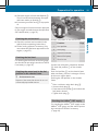
Stored data
Several
of the electronic components in your
engine system contain data memories.
These data memories temporarily or perma-
nently store technical information about:
R
the engine system state
R
events
R
malfunctions
In general, this technical information docu-
ments the state of a component, a module, a
system or the surroundings.
This includes, for example:
R
operating conditions of system compo-
nents, e.g. fluid levels
R
the vehicle/device status messages and
those of its individual components, e.g.
speed, deceleration in movement, acceler-
ator position
R
malfunctions and defects in important sys-
tem components
R
the vehicle/device reactions and operating
statuses in special driving situations
R
ambient conditions, e.g. outside tempera-
ture
8
Stored data
Introduction

This data is exclusively technical in nature
and can be used to:
R
assist in the detection and rectification of
faults and defects
R
analyse
vehicle functions, e.g. after an acci-
dent
The data cannot be used to trace the vehicle's
movements.
When you use one of the available services,
technical information may be read from the
event data memory and fault data memory.
Services include, for example:
R
repair services
R
service processes
R
implied warranty and guarantee cases
R
quality assurance
The information is read out by employees of
the service network (including manufactur-
ers) using special diagnostic testers. Further
information is available there if required.
After a fault has been rectified, the informa-
tion is deleted from the fault memory or is
continually overwritten.
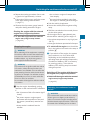
Qualified specialist workshop
A qualified specialist workshop has the nec-
essary specialist knowledge, tools and quali-
fications
to carry out the work required on the
engine to a professional standard. This is par-
ticularly applicable to work relevant to safety.
Observe the notes in the Maintenance Book-
let.
Always have the following maintenance work
carried out at a qualified specialist workshop:
R
work relevant to safety
R
service and maintenance work
R
repair work
R
modifications as well as installations and
conversions
R
work on electronic components
Please consult an MTU or MTU-authorised
Mercedes-Benz partner.
Further applicable documents
These operating instructions describe all
models and all standard and optional equip-
ment
available for your engine system within
the scope of delivery of Daimler AG. The
installation of the engine system into the vehi-
cle/device may require additional operating
instructions adapted to the vehicle/device
and the appropriate use thereof. These addi-
tional operating instructions will be provided
by the vehicle/device manufacturer (manu-
facturer of the end product). The additional
operating instructions will describe, in partic-
ular, the functions specific to the installation
and operation, the use of such functions as
well as warning and control mechanisms.
To use the engine correctly, you also require
the Maintenance Booklet.
For US-certified off-highway engines you also
require the "Emission Warranty" supplement.
Always keep these documents together with
the engine, vehicle or device. These docu-
ments should be passed on to the new owner
if you sell the engine, vehicle or device.
When carrying out maintenance work, you
require access to the Workshop Information
System (WIS) via the Internet. This access is
subject to a fee.
Current information on the system and prices
can be found at this web address: http://
service-parts.mercedes-benz.com. Click on
"EPC, WIS/ASRA" in the "Service and parts
information" tab and then on "WIS".
You can log in by clicking on "Register" on the
right-hand side.
Further applicable documents
9
Introduction
Z

10

General information ............................ 12
Engine overview .................................. 13
Exhaust gas aftertreatment over-
view ...................................................... 17
Electronic engine management ......... 18
BlueTec
®
exhaust gas aftertreat-
ment ..................................................... 20
Exhaust gas recirculation ................... 20
Warning and indicator lamps ............. 20
11
At a glance

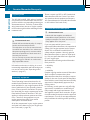
General information
The
engine is a four-stroke, water-cooled die-
sel engine with direct injection.
The engine is equipped with a common rail
diesel injection system, cooled and regulated
exhaust gas recirculation and turbocharging
with charge-air pressure control.
Depending on the engine output, engine tur-
bocharging is either by means of single-stage
exhaust turbocharging or two stage exhaust
gas turbocharging with two sequential
exhaust gas turbochargers of differing dimen-
sions.
The valve gear has two camshafts at the top,
which are driven via a gearwheel drive.
The engine features a single-piece cylinder
head. In the cylinder head there are two inlet
valves and two exhaust valves per cylinder.
The valves are arranged symmetrically. The
symmetrical valve arrangement is optimal for
combustion.
The exhaust gas aftertreatment unit is char-
acterised by the following technologies:
R
selective catalytic reduction (SCR) with
ammonia slip catalytic converter
R
the diesel oxidation catalytic converter
(DOC)
The engine brake is a decompression brake. It
has a controlled exhaust valve which gives it
high braking power. The engine brake is con-
trollable in steps or modulated.
12
General information
At a glance

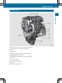
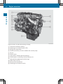
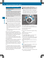
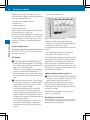
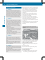
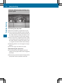
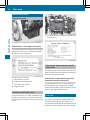
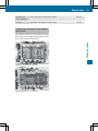
Engine overview
Engine overview: 4R 1000 with single-stage charging
:
Exhaust gas recirculation positioner
;
Rail
=
Fuel filter
?
External engine start/engine stop button
A
High-pressure fuel pump
B
Engine management control module (MCM)
C
Dipstick
D
Air compressor
E
Power-steering pump
F
Oil pan
G
Charge-air pipe (cold)
Engine overview
13
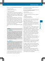
At a glance

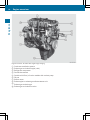
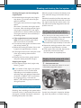
Engine overview: 4R 1000 with single-stage charging
:
Crankcase ventilation system
;
Exhaust gas recirculation pipe (cold)
=
Refrigerant compressor
?
Coolant thermostat
A
Combined oil filter/oil cooler module with coolant pump
B
Oil pan
C
Starter motor
D
Exhaust pipe to exhaust gas aftertreatment unit
E
Exhaust gas turbocharger
F
Exhaust gas recirculation cooler
14
Engine overview
At a glance


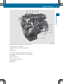
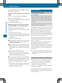
Engine overview: 6R 1000 with two-stage charging
:
Crankcase ventilation system
;
Exhaust gas recirculation pipe (cold)
=
Refrigerant compressor
?
Combined oil filter/oil cooler module with coolant pump
A
Oil pan
B
Starter motor
C
Low pressure exhaust gas turbocharger
D
Exhaust pipe to exhaust gas aftertreatment unit
E
High pressure exhaust gas turbocharger
F
Power take-off (PTO)
G
Boost pressure positioner
H
Exhaust gas recirculation cooler
16
Engine overview
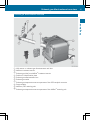
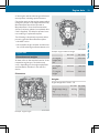
At a glance

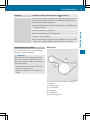
Exhaust gas aftertreatment overview
:
NOx sensor on exhaust gas aftertreatment unit inlet
;
AdBlue
®
treatment reactor
=
Exhaust gas inlet from AdBlue
®
treatment reactor
?
Position of identification plate
A
Exhaust gas aftertreatment box
B
Exhaust gas outlet
C
Exhaust gas temperature sensor upstream of the SCR catalytic converter
D
Pump module
E
AdBlue
®
/DEF metering unit
F
Exhaust gas temperature sensor upstream of the AdBlue
®
metering unit
Exhaust gas aftertreatment overview
17
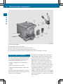
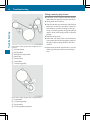
At a glance

:
Mounting brackets
;
Exhaust gas inlet from engine
=
Exhaust gas aftertreatment control unit (ACM)
?
NOx sensor at exhaust gas aftertreatment unit outlet
A
Exhaust gas temperature sensor downstream of the SCR catalytic converter
Electronic engine management
The engine system is equipped with an elec-
tronic engine management system which
comprises the following control units:
R
Engine management control module
(MCM)
R
Drive control system unit (CPC)
R
Exhaust gas aftertreatment control unit
(ACM)
The control units are connected in an elec-
tronic network. Data is exchanged via CAN
(Controller Area Network).
In addition to the engine, the exhaust gas
aftertreatment and the connection on the
vehicle/device, the electronic engine man-
agement system also monitors itself.
Depending on the malfunctions/failures
which occur, warning and information dis-
plays are activated
(Y page 20). The mal-
function is stored in the fault memory and if
necessary a safety and emergency mode is
automatically selected (Y page 36). If the
electronic engine management control
detects a fault, the fault code is stored in the
control units. It can then be read by a qualified
specialist workshop (Y page 9) using a diag-
nostic tester.
18
Electronic engine management
At a glance
La pagina sta caricando ...
La pagina sta caricando ...
La pagina sta caricando ...
La pagina sta caricando ...
La pagina sta caricando ...
La pagina sta caricando ...
La pagina sta caricando ...
La pagina sta caricando ...
La pagina sta caricando ...
La pagina sta caricando ...
La pagina sta caricando ...
La pagina sta caricando ...
La pagina sta caricando ...
La pagina sta caricando ...
La pagina sta caricando ...
La pagina sta caricando ...
La pagina sta caricando ...
La pagina sta caricando ...
La pagina sta caricando ...
La pagina sta caricando ...
La pagina sta caricando ...
La pagina sta caricando ...
La pagina sta caricando ...
La pagina sta caricando ...
La pagina sta caricando ...
La pagina sta caricando ...
La pagina sta caricando ...
La pagina sta caricando ...
La pagina sta caricando ...
La pagina sta caricando ...
La pagina sta caricando ...
La pagina sta caricando ...
La pagina sta caricando ...
La pagina sta caricando ...
La pagina sta caricando ...
La pagina sta caricando ...
La pagina sta caricando ...
La pagina sta caricando ...
La pagina sta caricando ...
La pagina sta caricando ...
La pagina sta caricando ...
La pagina sta caricando ...
La pagina sta caricando ...
La pagina sta caricando ...
La pagina sta caricando ...
La pagina sta caricando ...
La pagina sta caricando ...
La pagina sta caricando ...
La pagina sta caricando ...
La pagina sta caricando ...
La pagina sta caricando ...
La pagina sta caricando ...
La pagina sta caricando ...
La pagina sta caricando ...
La pagina sta caricando ...
La pagina sta caricando ...
La pagina sta caricando ...
La pagina sta caricando ...
La pagina sta caricando ...
La pagina sta caricando ...
La pagina sta caricando ...
La pagina sta caricando ...
La pagina sta caricando ...
La pagina sta caricando ...
La pagina sta caricando ...
La pagina sta caricando ...
La pagina sta caricando ...
La pagina sta caricando ...
-
 1
1
-
 2
2
-
 3
3
-
 4
4
-
 5
5
-
 6
6
-
 7
7
-
 8
8
-
 9
9
-
 10
10
-
 11
11
-
 12
12
-
 13
13
-
 14
14
-
 15
15
-
 16
16
-
 17
17
-
 18
18
-
 19
19
-
 20
20
-
 21
21
-
 22
22
-
 23
23
-
 24
24
-
 25
25
-
 26
26
-
 27
27
-
 28
28
-
 29
29
-
 30
30
-
 31
31
-
 32
32
-
 33
33
-
 34
34
-
 35
35
-
 36
36
-
 37
37
-
 38
38
-
 39
39
-
 40
40
-
 41
41
-
 42
42
-
 43
43
-
 44
44
-
 45
45
-
 46
46
-
 47
47
-
 48
48
-
 49
49
-
 50
50
-
 51
51
-
 52
52
-
 53
53
-
 54
54
-
 55
55
-
 56
56
-
 57
57
-
 58
58
-
 59
59
-
 60
60
-
 61
61
-
 62
62
-
 63
63
-
 64
64
-
 65
65
-
 66
66
-
 67
67
-
 68
68
-
 69
69
-
 70
70
-
 71
71
-
 72
72
-
 73
73
-
 74
74
-
 75
75
-
 76
76
-
 77
77
-
 78
78
-
 79
79
-
 80
80
-
 81
81
-
 82
82
-
 83
83
-
 84
84
-
 85
85
-
 86
86
-
 87
87
-
 88
88


MTU 6R 1000 series Operating Instructions Manual
- Tipo
- Operating Instructions Manual
- Questo manuale è adatto anche per
in altre lingue
- English: MTU 6R 1000 series
Altri documenti
-
Dometic PJS1000 Istruzioni per l'uso
-
Yanmar 6HYM-WET Istruzioni per l'uso
-
Ingersoll-Rand R30 Product Maintenance Information
-
Thermo Scientific Orion RDO Guida Rapida
-
Oakton WD-35640-51 Manuale del proprietario
-
ProMinent gamma/ X GMXa Operating Instructions Manual
-
Vaillant aroTHERM VWL 85/2 A Operating Instructions Manual
-
 Refco WIRELESS-CLAMP WTC Manuale utente
-
Ferrari F40 Manuale utente
-
 VM Motori MR 700 Manuale utente

