ProMinent gamma/ X GMXa Operating Instructions Manual
- Tipo
- Operating Instructions Manual

Solenoid Metering Pump
gamma/ X, GMXa
Operating instructions
EN
Original Operating Instructions (2006/42/EC)Part no. 984586 BA G 054 04/17 EN
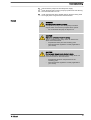
Please carefully read these operating instructions before use. · Do not discard.
The operator shall be liable for any damage caused by installation or operating errors.
The latest version of the operating instructions are available on our homepage.

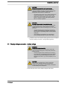
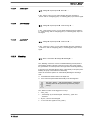
Read the following supplementary information in its entirety! Should you
already know this information, you will benefit more from referring to the
operating instructions.
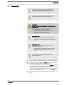
The following are highlighted separately in the document:
n Enumerated lists
Instructions
ð
Outcome of the instructions
Ä „State the identity code and serial number“ on page 2
: Links to points
in this chapter
- refer to ... : References to points in this document or another document
[Keys]
„Menu level 1
è
Menu level 2
è
Menu level ...“
: Menu paths
„Software interface text“
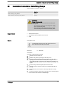
Information
This provides important information relating to the cor‐
rect operation of the unit or is intended to make your
work easier.
Safety Information
Safety information is identified by pictograms - see "Safety Chapter".
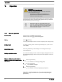
Please state the identity code and serial number, which you can find on
the nameplate or in the menu under
„Setting / Menu
è
Information“
when
you contact us or order spare parts. This enables the unit type and mate‐
rial versions to be clearly identified.
Supplementary information
Fig. 1: Please read!
State the identity code and serial number
Supplemental directives
2

Table of contents
1
Identity Code................................................................................... 6
2 About this pump............................................................................... 8
3 Safety Chapter................................................................................. 9
4 Storage, Transport and Unpacking................................................ 14
5 Overview of Equipment and Control Elements.............................. 15
5.1 Overview of equipment......................................................... 15
5.2 Control elements................................................................... 16
5.2.1 Control elements................................................................ 16
5.2.2 Key functions...................................................................... 20
6 Functional Description................................................................... 21
6.1 Liquid End............................................................................. 21
6.2 Drive unit............................................................................... 21
6.3 Capacity................................................................................ 23
6.4 Self-Bleeding......................................................................... 23
6.5 Operating modes................................................................... 23
6.6 Functions............................................................................... 24
6.7 Relay (Options)..................................................................... 24
6.8 LED Displays......................................................................... 25
6.9 Hierarchy of Operating Modes, Functions and Fault Sta‐
tuses......................................................................................
25
7 Assembly....................................................................................... 27
8 Installation, hydraulic..................................................................... 29
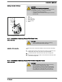
8.1 Installing hose lines............................................................... 30
8.1.1 Installation of Metering Pumps Without Bleed Valve......... 30
8.1.2 Installation of Metering Pumps With Bleed Valve.............. 33
8.1.3 Installation of Metering Pumps With Self-bleeding (SEK
Type).................................................................................. 33
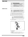
8.2 Basic installation notes.......................................................... 35
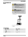
9 Installation, electrical..................................................................... 36
9.1 Supply voltage connector - mains voltage............................ 37
9.2 Description of the Terminals................................................. 38
9.2.1 "External control" terminal.................................................. 38
9.2.2 "Level switch" terminal....................................................... 39
9.2.3 "Dosing monitor" terminal................................................... 39
9.2.4 "Diaphragm rupture indicator" terminal.............................. 40
9.2.5 Relay.................................................................................. 40
10 Basic Set-up Principles.................................................................. 44
10.1 Basic Principles for Setting up the Control.......................... 44
10.2 Checking adjustable variables............................................ 46
10.3 Changing to set up mode.................................................... 46
11 Set Up /
„Menu“
............................................................................ 47
11.1
„Information“
....................................................................... 47
11.2
„Settings“
............................................................................ 47
11.2.1
„Operating Mode“
............................................................ 47
11.2.2
„Automatic“
...................................................................... 52
11.2.3
„Stroke length“
................................................................ 52
11.2.4 Metering........................................................................... 53
11.2.5 Concentration................................................................... 57
11.2.6 Calibration........................................................................ 63
11.2.7 System............................................................................. 64
11.2.8 Inputs/outputs................................................................... 66
11.2.9 Bleeding........................................................................... 69
Table of contents
3

11.2.10
„Priming time“
................................................................ 70
11.2.11
„Set time“
...................................................................... 71
11.2.12
„Date“
............................................................................ 71
11.3 Timer................................................................................... 71
11.3.1 Timer activation................................................................ 71
11.3.2 Setting the timer............................................................... 72
11.3.3 Clear all............................................................................ 74
11.3.4 Example........................................................................... 74
11.4
„Service“
............................................................................. 74
11.4.1
„Access protect.“
............................................................. 74
11.4.2
„Password “
..................................................................... 75
11.4.3
„Clear counter“
................................................................ 75
11.4.4
„Log book“
....................................................................... 75
11.4.5
„Replace diaphragm“
...................................................... 76
11.4.6
„Display“
.......................................................................... 76
11.4.7
„Factory settings“
............................................................ 76
11.4.8 Diaphragm part number: XXXXXXX................................ 76
11.4.9 Spare parts kit part number: XXXXXXX........................... 77
11.5
„Language“
......................................................................... 77
12 Operation....................................................................................... 78
12.1 Manual operation................................................................ 78
13 Maintenance.................................................................................. 80
14 Carrying out repairs....................................................................... 82
14.1 Replacing the diaphragm.................................................... 83
14.2 Cleaning the Diaphragm Rupture Indicator......................... 85
14.3 Cleaning valves................................................................... 85
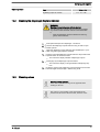
15 Troubleshooting............................................................................. 86
15.1 Faults without a fault message............................................ 86
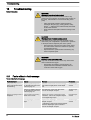
15.2 Faults with error message................................................... 87
15.2.1 Fault messages on the LCD screen................................. 87
15.2.2 Warning messages on the LCD screen........................... 88
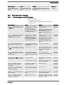
15.2.3 All Other Faults................................................................ 89
15.3 Log book............................................................................. 89
15.3.1 Fault messages in the log book....................................... 89
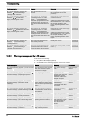
15.3.2 Warning messages in the log book.................................. 90
15.3.3 Event messages in the log book...................................... 90
15.3.4 Log book entry - Detailed view......................................... 91
16 Decommissioning.......................................................................... 92
17 Technical data............................................................................... 94
17.1 Performance data................................................................ 94
17.2 Accuracy............................................................................. 95
17.2.1 Standard Liquid End......................................................... 95
17.2.2 Self-Bleeding Liquid End.................................................. 95
17.3 Viscosity.............................................................................. 95
17.4 Material specifications......................................................... 96
17.5 Electrical data...................................................................... 96
17.6 Temperatures...................................................................... 96
17.7 Climate................................................................................ 97
17.8 Degree of Protection and Safety Requirements.................. 97
17.9 Compatibility........................................................................ 97
17.10 Shipping weight................................................................. 98
17.11 Sound pressure level........................................................ 98
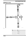
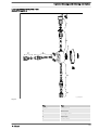
18 Exploded Drawings and Ordering Information............................... 99
18.1 Exploded drawings.............................................................. 99
Table of contents
4

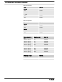
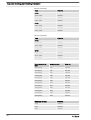
18.2 Ordering information ........................................................ 139
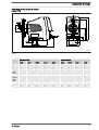
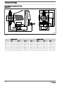
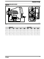
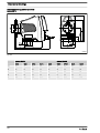
19 Dimensional Drawings................................................................. 140
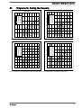
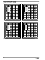
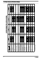
20
Diagrams for Setting the Capacity............................................... 149
21 Declaration of Conformity for Machinery..................................... 152
22 Approvals..................................................................................... 153
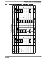
23 Operating/Set-up Overview of the gamma/ X.............................. 154
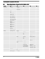
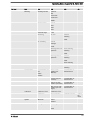
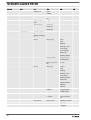
24 Operating Menu of gamma/ X, Entire Unit................................... 156
25 Continuous Displays and Secondary Displays............................ 161
26 Installation instructions: Retrofitting Relays ................................ 163
27 Index............................................................................................ 165
Table of contents
5

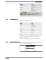
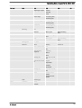
1 Identity Code
Product range gamma/ X
GMXa Type
- - - - Performance data and type - see nameplate
Dosing head material
PP Polypropylene
NP Clear acrylic
PV PVDF
TT PTFE + carbon
SS Stainless steel
Seal material
B FPM
E EPDM
T PTFE
F PTFE, FDA-compliant
Dosing head design
0 Without bleed valve, without valve spring
1 Without bleed valve, with valve spring
2 With bleed valve, without valve spring
3 With bleed valve, with valve spring
4 Without bleed valve, with valve spring for more high-viscosity media
7 Self-bleeding with groove (SEK)
9 Self-bleeding with bypass (SEK)
Hydraulic connector
0 Standard connection in line with technical data
5 Connector for 12/6 hose, suction side standard
9 Connector for 10/4 hose, discharge side only, suction side standard
Diaphragm rupture indicator
0 Without diaphragm rupture indicator
1 With diaphragm rupture indicator, optical sensor, electrical signal
Design
0 Hous. RAL5003 / Hood RAL2003
M modified
Logo
0 with ProMinent logo
Electrical connection
U 100-230 V ± 10%, 50/60 Hz
Cable and plug
A 2 m European
B 2 m Swiss
C 2 m Australian
Identity Code
6

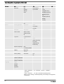
Product range gamma/ X
D 2 m USA / 115 V
E 2 m Great Britain
1 2 m open end
.. ...
Relay, pre-set to ...
0 No relay -
1 1 x changeover contact 230 V
– 8 A
Fault indicating relay (N/C)
4 2 x N/O 24 V – 100 mA as 1 + pacing relay
C 1 x N/O 24 V – 100 mA, and 1
x 4-20 mA output
As 1 + 4-20 mA output
F With automatic bleed valve 230 V
G with automatic bleed valve
and relay output
24 VDC
.. ...
Accessories
0 without accessories
1 With foot and injection valve, 2 m suction line, 5 m metering
line
4 Multifunctional valve and accessories
Control version
0 Manual + external contact with pulse control
3 Manual + external contact with pulse control + analogue
0/4-20mA
4 As 0 + 4-week process timer
5 As 3 + 4-week process timer
C As 3 + CANopen
R
As 3 + PROFIBUS
®
interface, M12
Dosing monitor
0 Dynamic dosing monitor
Remote stop / Remote control
0 without Bluetooth
B with Bluetooth
Language
EN German
EN English
ES Spanish
FR French
... ...
Identity Code
7

2 About this pump
Pumps in the gamma/ X product range are microprocessor-controlled sole‐
noid metering pumps with the following characteristics:
n Simple adjustment of the capacity directly in l/h
n Available material combinations: PP, PVDF, clear acrylic, PTFE and
stainless steel
n Special dosing head designs for gaseous and high-viscosity media
n Illuminated LC display and 3-LED display for operating, warning and
error messages, visible from all sides
n Factor with external contact control 99:1 ... 1:99
n Batch operation with max. 99,999 strokes/start pulse
n Input of concentration for simple adjustment with volume-proportional
metering tasks
n Stroke rate adjustment in 1 stroke/hour increments from 0 ... 12,000
strokes/h
n Electronic stroke length adjustment, continuous from 0 ... 100% (rec‐
ommended 30 ... 100%)
n Connector for 2-stage level switch
n External control via 0/4-20 mA standard signal with adjustable assign‐
ment of signal value to stroke rate
n Optional 4-20 mA output for remote transmission of stroke length and
stroke rate
n Universal power supply unit 100 V - 230 V, 50/60 Hz
n Optional 230 V relay module, can also be retrofitted easily and
securely
n Optional 24 V combined relay, can also be retrofitted easily and
securely
The hydraulic parts of the gamma/ X are identical to those of the Beta
®
(not with types 0220, 0424 and 0245).
About this pump
About this pump
8

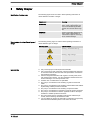
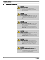
3 Safety Chapter
The following signal words are used in these operating instructions to
denote different severities of danger:
Signal word Meaning
WARNING Denotes a possibly dangerous sit‐
uation. If this is disregarded, you
are in a life-threatening situation
and this can result in serious inju‐
ries.
CAUTION Denotes a possibly dangerous sit‐
uation. If this is disregarded, it
could result in slight or minor inju‐
ries or material damage.
The following warning signs are used in these operating instructions to
denote different types of danger:
Warning signs Type of danger
Warning – automatic start-up.
Warning – high-voltage.
Warning – danger zone.
n Only use the pump to meter liquid feed chemicals.
n Only use the pump after it has been correctly installed and started up
in accordance with the technical data and specifications contained in
the operating instructions.
n Observe the general limitations with regard to viscosity limits, chem‐
ical resistance and density - see also ProMinent resistance list in the
Product Catalogue or at www.prominent.com!
n All other uses or modifications are prohibited.
n The pump is not intended for the metering of gaseous media and
solids.
n The pump is not intended for the metering of flammable media without
implementing suitable protective measures.
n The pump is not intended for the metering of explosive media.
n The pump is not intended for operation in areas at risk from explosion.
n The pump is not intended for exterior applications without the imple‐
mentation of suitable protective measures.
n The pump should only be operated by trained and authorised per‐
sonnel, see the following "Qualifications" table.
n You are obliged to observe the information contained in the operating
instructions at the different phases of the unit's service life.
Identification of safety notes
Warning signs denoting different types of
danger
Intended Use
Safety Chapter
9

WARNING!
Warning about personal and material damage
The pump can start to pump, as soon as it is connected
to the mains voltage.
– Install an emergency cut-off switch in the pump
power supply line or integrate the pump in the emer‐
gency cut-off management of the system.
WARNING!
Warning of personal injury and material damage
The pump can start pumping as soon as it has cooled
down after the error
„temperature“
.
– Take this into account with the pump and your
installation.
WARNING!
Danger of electric shock
A mains voltage may exist inside the pump housing.
– If the pump housing has been damaged, you must
disconnect it from the mains immediately. It may
only be returned to service after an authorised
repair.
WARNING!
Warning of hazardous feed chemical
Should a dangerous feed chemical be used: it may
escape from the hydraulic components when working on
the pump, material failure or incorrect handling of the
pump.
– Take appropriate protective measures before
working on the pump (e.g. safety glasses, safety
gloves, ...). Adhere to the material safety data sheet
for the feed chemical.
–
Drain and flush the liquid end before working on the
pump.
WARNING!
Fire danger
When pumping inflammable media the operator must
take suitable safety precautions.
Safety information
Safety Chapter
10

WARNING!
Danger from hazardous substances!
Possible consequence: Fatal or very serious injuries.
Please ensure when handling hazardous substances
that you have read the latest safety data sheets provided
by the manufacture of the hazardous substance. The
actions required are described in the safety data sheet.
Check the safety data sheet regularly and replace, if
necessary, as the hazard potential of a substance can
be re-evaluated at any time based on new findings.
The system operator is responsible for ensuring that
these safety data sheets are available and that they are
kept up to date, as well as for producing an associated
hazard assessment for the workstations affected.
CAUTION!
Warning of feed chemical spraying around
Feed chemical can spray out of the hydraulic compo‐
nents if they are manipulated or opened due to pressure
in the liquid end and adjacent parts of the system.
– Disconnect the pump from the mains power supply
and ensure that it cannot be switched on again by
unauthorised persons.
– Depressurise the system before commencing any
work on hydraulic parts.
CAUTION!
Warning of feed chemical spraying around
The metering pump can generate a multiple of its rated
pressure. Hydraulic parts can rupture if a discharge line
is blocked.
– Correctly install a relief valve in the discharge line
downstream of the metering pump.
CAUTION!
Warning of feed chemical spraying around
An unsuitable feed chemical can damage the parts of
the pump that come into contact with the chemical.
– Take into account the resistance of the wetted mate‐
rials and the ProMinent Resistance List when
selecting the feed chemical - see the ProMinent
Product Catalogue or visit ProMinent.
CAUTION!
Danger of injury to personnel and material damage
The use of untested third party components can result in
injury to personnel and material damage.
– Only fit parts to metering pumps that have been
tested and recommended by ProMinent.
Safety Chapter
11

CAUTION!
Danger from incorrectly operated or inadequately main‐
tained pumps
Danger can arise from a poorly accessible pump due to
incorrect operation and poor maintenance.
– Ensure that the pump is accessible at all times.
–
Adhere to the maintenance intervals.
CAUTION!
Danger from incorrect dosing
The metering behaviour of the pump changes if a dif‐
ferent liquid end size is fitted.
– Reprogram the pump in the
„Menu / Information
è
Settings
è
System
è
Change head type“
menu.
CAUTION!
Warning against illegal operation
Observe the regulations that apply where the device is
installed.
n Covers for the slots for relays and optional modules - see the chapter
entitled "Overview of Equipment and Control Elements"
Customers should only remove the cover for the slots for relays and
optional modules and/or a relay or optional module in line with the supple‐
mentary instructions for the relays and optional modules.
Customer should only remove the dosing head in accordance with the
"Repair" chapter.
Only the ProMinent Service department is authorised to open the housing
and the hood (housing the control elements).
In an emergency, either disconnect the mains plug, press
[Start/Stop]
or press the Emergency Stop switch installed on the customer's side or
disconnect the pump from the mains/power supply in line with the Emer‐
gency Stop management guidelines for your system.
If feed chemical escapes, also ensure that the pump's hydraulic environ‐
ment is at atmospheric pressure. Adhere to the material safety data sheet
for the feed chemical.
Task Qualification
Storage, transport, unpacking Instructed person
Assembly Technical personnel, service
Planning the hydraulic installation Qualified personnel who have a
thorough knowledge of metering
pumps
Hydraulic installation Technical personnel, service
Installation, electrical Electrical technician
Operation Instructed person
Maintenance, repair Technical personnel, service
Isolating protective equipment
Information in the event of an emergency
Qualification of personnel
Safety Chapter
12

Task Qualification
Decommissioning, disposal Technical personnel, service
Troubleshooting Technical personnel, electrical
technician, instructed person,
service
Explanation of the table:
Qualified personnel
A qualified employee is deemed to be a person who is able to assess the
tasks assigned to him and recognise possible dangers based on his/her
technical training, knowledge and experience, as well as knowledge of
pertinent regulations.
Note:
A qualification of equal validity to a technical qualification can also be
gained by several years of employment in the relevant field of work.
Electrical technician
An electrical technician is able to complete work on electrical systems and
recognise and avoid possible dangers independently based on his/her
technical training and experience, as well as knowledge of pertinent stand‐
ards and regulations.
The electrical technician should be specifically trained for the working
environment in which he is employed and know the relevant standards
and regulations.
An electrical technician must comply with the provisions of the applicable
statutory directives on accident prevention.
Instructed person
An instructed person is deemed to be a person who has been instructed
and, if required, trained in the tasks assigned to him/her and possible dan‐
gers that could result from improper behaviour, as well as having been
instructed in the required protective equipment and protective measures.
Service
The Service department refers to service technicians, who have received
proven training and have been authorised by ProMinent to work on the
system.
Sound pressure level LpA < 70 dB according to EN ISO 20361
at maximum stroke length, maximum stroke rate, maximum back pressure
(water)
Sound pressure level
Safety Chapter
13

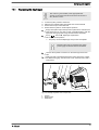
4 Storage, Transport and Unpacking
WARNING!
Only return metering pumps for repair in a cleaned state
and with a flushed liquid end - refer to "Decommis‐
sioning!
Only return metering pumps with a completed Decon‐
tamination Declaration form. The Decontamination Dec‐
laration constitutes an integral part of an inspection /
repair order. A unit can only be inspected or repaired
when a Declaration of Decontamination Form is sub‐
mitted that has been completed correctly and in full by
an authorised and qualified person on behalf of the
pump operator.
The "Decontamination Declaration Form" can be found
on our homepage.
CAUTION!
Danger of material damage
The device can be damaged by incorrect or improper
storage or transportation!
– The unit should only be stored or transported in a
well packaged state - preferably in its original pack‐
aging.
– The packaged unit should also only be stored or
transported in accordance with the stipulated
storage conditions.
– The packaged unit should be protected from mois‐
ture and the ingress of chemicals.
Ambient conditions - refer to "Technical Data" chapter.
Compare the delivery note with the scope of delivery:
n Metering pump with mains cable
n Connector kit for hose/pipe connection (optional)
n Product-specific operating instructions with EC Declaration of Con‐
formity
n Optional accessories
Safety Information
Ambient conditions
Scope of delivery
Storage, Transport and Unpacking
14

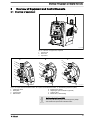
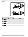
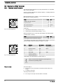
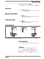
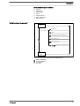
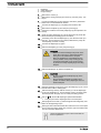
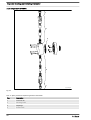
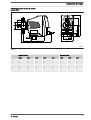
5 Overview of Equipment and Control Elements
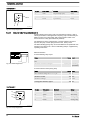
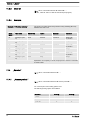
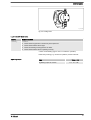
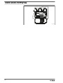
5.1
Overview of equipment
1
P_G_0063_SW
2 3
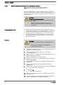
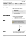
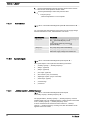
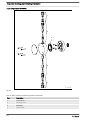
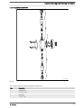
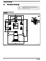
Fig. 2: Overview of equipment, complete
1 Control unit
2 Drive unit
3 Liquid end
1
2
3
4
5
6
7
1
2
3
4
5
6
7
8
2
3
1
6
7
A.
B.
C.
P_G_0053_SW
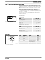
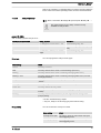
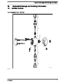
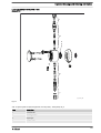
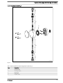
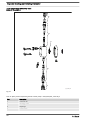
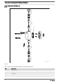
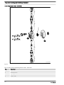
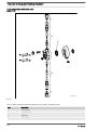
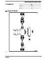
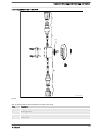
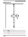
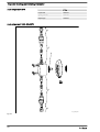
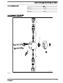
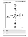
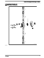
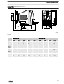
Fig. 3: A. Liquid end with PV bleed valve; B. Liquid end with NP bleed valve; C. Self-bleeding liquid end (SEK)
1 Discharge valve
2 Backplate
3 Dosing head
4 Bleed valve
5 Bypass hose sleeve
6 Diaphragm rupture indicator (optional)
7 Suction valve
8 Bleed valve, self-bleeding
Self-bleeding liquid ends (SER)
Externally self-bleeding liquid ends with groove (SER)
look identical to liquid ends with bleed valve.
Overview of Equipment and Control Elements
15

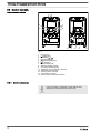
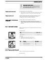
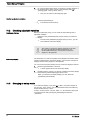
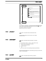
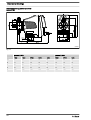
5.2 Control elements
11 13
14
12
3
1
5
4
2
10
9
8
7
6
a)
b)
P_G_0051_SW
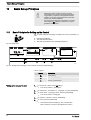
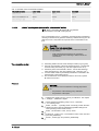
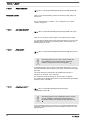
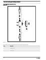
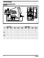
Fig. 4
1 LCD screen
2
[Menu]
key
3
Clickwheel
4
[Priming]
key
5
[STOP/START]
key
6
[Back]
key
7 Fault indicator (red)
8 Warning indicator (yellow)
9 Operating indicator (green)
10 "Diaphragm rupture indicator" terminal
11 "External control" terminal
12 "Dosing monitor" terminal
13 "Level switch" terminal
14 Slot for relays and optional modules
5.2.1 Control elements
Use this overview to familiarise yourself with the keys
and the other control elements on the pump!
Control elements, overview
Overview of Equipment and Control Elements
16

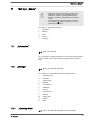
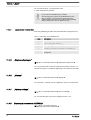
12.012.0
12000
2.5
CONTACT
memory
bar
l/h
CAN
open
hh
B0778
1
3
2
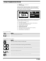
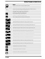
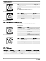
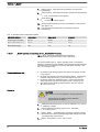
Fig. 5: Construction of continuous display
Pressure display, identifier and fault dis‐
plays on the LCD screen
Overview of Equipment and Control Elements
17

1 Status bar
2 Continuous display, central area
3 Secondary display
Refer to the chapter entitled "Main Displays and Secondary Displays" in
the Appendix for the different main displays and secondary displays.
The LCD screen supports the operation and adjustment of the pump by
providing different information and identifiers:
12.012.0
12000
2.5
Dosing monitor!
CONTACT
memory
bar
l/h
CAN
open
hh
12000
ANALOGUE
hh
Input signal < 4 mA
i < 4 mAi < 4 mA
B0605
a)
b)
i < 4 mA!
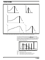
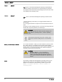
Fig. 6: a) Continuous display with warning message; b) Continuous display
with fault message. Explanation of the symbols in the following tables.
The above Figure, Part a) shows that:
n The pump is in operation
n Is in
„Contact“
operating mode with "memory" stroke memory.
n The average system pressure is 2.5 bar
n A dosing monitor is connected
n A CAN module is being used
n A log entry has been made
n A warning message for the
„dosing monitor“
is pending
n The capacity of 12.0 l/h has been set
n The stroke rate is 12,000 strokes / h
Tab. 1: Pressure display
Display Meaning
Displays the average system pressure
Tab. 2: Identifier and error displays:
Identifier Meaning
The pump is working or waiting for a starting signal.
The pump was manually stopped using the
[STOP/START]
key.
The pump was remotely stopped (Pause) - via the "External" terminal.
The pump was stopped by an error.
Only with cyclical batch metering: the pump waits for the next cycle.
Overview of Equipment and Control Elements
18

Identifier Meaning
Only with
„Access. protect“
: the pump software is locked.
„AUX“
The pump is currently pumping at auxiliary capacity and/or auxiliary frequency.
„memory“
Only in
„CONTACT“
and
„BATCH“
operating modes:
The auxiliary function "Stroke memory" has been set.
The pump is in
„ANALOGUE“
operating mode.
The
„Curve
è
linear“
type of processing is set.
The pump is in
„ANALOGUE“
operating mode.
The
„Curve
è
Upper side band“
type of processing is set.
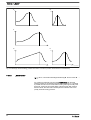
„Metering
è
Discharge stroke
è
optimum“
metering profile has been set.
„Metering
è
Discharge stroke
è
fast“
metering profile has been set.
„Metering
è
Discharge stroke
è
sine mode“
metering profile has been set.
„Metering
è
Discharge stroke
è
continuous“
metering profile has been set.
„Metering
è
Discharge stroke
è
DFMa“
metering profile has been set.
„Metering
è
Discharge stroke
è
normal“
metering profile has been set.
„Metering
è
Discharge stroke
è
HV1“
metering profile has been set.
„Metering
è
Discharge stroke
è
HV2“
metering profile has been set.
„Metering
è
Discharge stroke
è
HV3“
metering profile has been set.
A dosing monitor "Flow Control" is connected.
A diaphragm rupture indicator is connected.
The pump has created a log about the operation.
Overview of Equipment and Control Elements
19

Identifier Meaning
The pump is in the
„Menu“
(Set up).
Further explanations can be found in the "Trouble‐
shooting" chapter.
The pump only shows the metering volume and the
capacity in the calibrated state in l or l/h or in gal or
gal/h.
5.2.2 Key functions
Key Application In the continuous displays In the menu
[Back]
press - Move back to the previous menu
point (or a continuous display) -
without saving
[STOP/
START]
press Stop pump, Stop pump,
Start pump Start pump
[Menu key]
press Move to the menu Move back to a continuous display
[Priming key]
press Priming * Priming *
[Clickwheel]
press Start batch (only in
„Batch“
operating
mode)
Acknowledge errors
Move to next menu option (or a
continuous display)
Confirm entry and save
[Clickwheel]
turn Switch between the continuous dis‐
plays
Change figure or change selection
* When priming the pump does not run at maximum
stroke rate.
If
[Priming] is pressed in „Stop“ state, then [Priming]
has top priority as long as the button is pressed.
Refer to the "Set-up Basics" chapter to adjust figures
Overview of Equipment and Control Elements
20
La pagina si sta caricando...
La pagina si sta caricando...
La pagina si sta caricando...
La pagina si sta caricando...
La pagina si sta caricando...
La pagina si sta caricando...
La pagina si sta caricando...
La pagina si sta caricando...
La pagina si sta caricando...
La pagina si sta caricando...
La pagina si sta caricando...
La pagina si sta caricando...
La pagina si sta caricando...
La pagina si sta caricando...
La pagina si sta caricando...
La pagina si sta caricando...
La pagina si sta caricando...
La pagina si sta caricando...
La pagina si sta caricando...
La pagina si sta caricando...
La pagina si sta caricando...
La pagina si sta caricando...
La pagina si sta caricando...
La pagina si sta caricando...
La pagina si sta caricando...
La pagina si sta caricando...
La pagina si sta caricando...
La pagina si sta caricando...
La pagina si sta caricando...
La pagina si sta caricando...
La pagina si sta caricando...
La pagina si sta caricando...
La pagina si sta caricando...
La pagina si sta caricando...
La pagina si sta caricando...
La pagina si sta caricando...
La pagina si sta caricando...
La pagina si sta caricando...
La pagina si sta caricando...
La pagina si sta caricando...
La pagina si sta caricando...
La pagina si sta caricando...
La pagina si sta caricando...
La pagina si sta caricando...
La pagina si sta caricando...
La pagina si sta caricando...
La pagina si sta caricando...
La pagina si sta caricando...
La pagina si sta caricando...
La pagina si sta caricando...
La pagina si sta caricando...
La pagina si sta caricando...
La pagina si sta caricando...
La pagina si sta caricando...
La pagina si sta caricando...
La pagina si sta caricando...
La pagina si sta caricando...
La pagina si sta caricando...
La pagina si sta caricando...
La pagina si sta caricando...
La pagina si sta caricando...
La pagina si sta caricando...
La pagina si sta caricando...
La pagina si sta caricando...
La pagina si sta caricando...
La pagina si sta caricando...
La pagina si sta caricando...
La pagina si sta caricando...
La pagina si sta caricando...
La pagina si sta caricando...
La pagina si sta caricando...
La pagina si sta caricando...
La pagina si sta caricando...
La pagina si sta caricando...
La pagina si sta caricando...
La pagina si sta caricando...
La pagina si sta caricando...
La pagina si sta caricando...
La pagina si sta caricando...
La pagina si sta caricando...
La pagina si sta caricando...
La pagina si sta caricando...
La pagina si sta caricando...
La pagina si sta caricando...
La pagina si sta caricando...
La pagina si sta caricando...
La pagina si sta caricando...
La pagina si sta caricando...
La pagina si sta caricando...
La pagina si sta caricando...
La pagina si sta caricando...
La pagina si sta caricando...
La pagina si sta caricando...
La pagina si sta caricando...
La pagina si sta caricando...
La pagina si sta caricando...
La pagina si sta caricando...
La pagina si sta caricando...
La pagina si sta caricando...
La pagina si sta caricando...
La pagina si sta caricando...
La pagina si sta caricando...
La pagina si sta caricando...
La pagina si sta caricando...
La pagina si sta caricando...
La pagina si sta caricando...
La pagina si sta caricando...
La pagina si sta caricando...
La pagina si sta caricando...
La pagina si sta caricando...
La pagina si sta caricando...
La pagina si sta caricando...
La pagina si sta caricando...
La pagina si sta caricando...
La pagina si sta caricando...
La pagina si sta caricando...
La pagina si sta caricando...
La pagina si sta caricando...
La pagina si sta caricando...
La pagina si sta caricando...
La pagina si sta caricando...
La pagina si sta caricando...
La pagina si sta caricando...
La pagina si sta caricando...
La pagina si sta caricando...
La pagina si sta caricando...
La pagina si sta caricando...
La pagina si sta caricando...
La pagina si sta caricando...
La pagina si sta caricando...
La pagina si sta caricando...
La pagina si sta caricando...
La pagina si sta caricando...
La pagina si sta caricando...
La pagina si sta caricando...
La pagina si sta caricando...
La pagina si sta caricando...
La pagina si sta caricando...
La pagina si sta caricando...
La pagina si sta caricando...
La pagina si sta caricando...
La pagina si sta caricando...
La pagina si sta caricando...
La pagina si sta caricando...
La pagina si sta caricando...
La pagina si sta caricando...
La pagina si sta caricando...
La pagina si sta caricando...
La pagina si sta caricando...
La pagina si sta caricando...
La pagina si sta caricando...
La pagina si sta caricando...
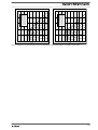
-
 1
1
-
 2
2
-
 3
3
-
 4
4
-
 5
5
-
 6
6
-
 7
7
-
 8
8
-
 9
9
-
 10
10
-
 11
11
-
 12
12
-
 13
13
-
 14
14
-
 15
15
-
 16
16
-
 17
17
-
 18
18
-
 19
19
-
 20
20
-
 21
21
-
 22
22
-
 23
23
-
 24
24
-
 25
25
-
 26
26
-
 27
27
-
 28
28
-
 29
29
-
 30
30
-
 31
31
-
 32
32
-
 33
33
-
 34
34
-
 35
35
-
 36
36
-
 37
37
-
 38
38
-
 39
39
-
 40
40
-
 41
41
-
 42
42
-
 43
43
-
 44
44
-
 45
45
-
 46
46
-
 47
47
-
 48
48
-
 49
49
-
 50
50
-
 51
51
-
 52
52
-
 53
53
-
 54
54
-
 55
55
-
 56
56
-
 57
57
-
 58
58
-
 59
59
-
 60
60
-
 61
61
-
 62
62
-
 63
63
-
 64
64
-
 65
65
-
 66
66
-
 67
67
-
 68
68
-
 69
69
-
 70
70
-
 71
71
-
 72
72
-
 73
73
-
 74
74
-
 75
75
-
 76
76
-
 77
77
-
 78
78
-
 79
79
-
 80
80
-
 81
81
-
 82
82
-
 83
83
-
 84
84
-
 85
85
-
 86
86
-
 87
87
-
 88
88
-
 89
89
-
 90
90
-
 91
91
-
 92
92
-
 93
93
-
 94
94
-
 95
95
-
 96
96
-
 97
97
-
 98
98
-
 99
99
-
 100
100
-
 101
101
-
 102
102
-
 103
103
-
 104
104
-
 105
105
-
 106
106
-
 107
107
-
 108
108
-
 109
109
-
 110
110
-
 111
111
-
 112
112
-
 113
113
-
 114
114
-
 115
115
-
 116
116
-
 117
117
-
 118
118
-
 119
119
-
 120
120
-
 121
121
-
 122
122
-
 123
123
-
 124
124
-
 125
125
-
 126
126
-
 127
127
-
 128
128
-
 129
129
-
 130
130
-
 131
131
-
 132
132
-
 133
133
-
 134
134
-
 135
135
-
 136
136
-
 137
137
-
 138
138
-
 139
139
-
 140
140
-
 141
141
-
 142
142
-
 143
143
-
 144
144
-
 145
145
-
 146
146
-
 147
147
-
 148
148
-
 149
149
-
 150
150
-
 151
151
-
 152
152
-
 153
153
-
 154
154
-
 155
155
-
 156
156
-
 157
157
-
 158
158
-
 159
159
-
 160
160
-
 161
161
-
 162
162
-
 163
163
-
 164
164
-
 165
165
-
 166
166
-
 167
167
-
 168
168
-
 169
169
-
 170
170
-
 171
171
-
 172
172


ProMinent gamma/ X GMXa Operating Instructions Manual
- Tipo
- Operating Instructions Manual
in altre lingue
- English: ProMinent gamma/ X GMXa
Documenti correlati
-
ProMinent GMXa Operating Instructions Manual
-
-
-
-
-
Altri documenti
-
Grundfos DME 375 Installation And Operating Instructions Manual
-
CTX BOMBAPRO PH-RX Operating
-
Grundfos DTS Installation And Operating Instructions Manual
-
Dynisco SPXD Manuale utente
-
MTU 4R 1000 SERIES Operating Instructions Manual
-
Ferrari Mondial Manuale del proprietario
-
-
-
Grundfos DMM 23 Installation And Operating Instructions Manual
-