
RB14604
Rackmount Chassis User Manual
July 2020 Version 1.3
A document provides an overview of product features, functions, architecture, and support specifications.

DISCLAIMERS
No license (express or implied, by estoppel or otherwise) to any intellectual property rights is granted by this document.
Chenbro disclaims all express and implied warranties, including without limitation, the implied warranties of merchantability, fitness
for a particular purpose, and non-infringement, as well as any warranty arising from course of performance, course of dealing, or
usage in trade.
This document contains information on products, services and/or processes in development. All information provided here is subject
to change without notice.
The products and services described may contain defects or errors known as errata which may cause deviations from published
specifications. Current characterized errata are available on request.
Chenbro, and the Chenbro logo are trademarks of Chenbro Micom Co., Ltd. in the worldwide.
*Other names and brands may be claimed as the property of others
© 2020 Chenbro Micom Co., Ltd.

Warnings
Only trained and qualified personnel should be allowed to install, replace, or service this equipment.
Heed safety instructions: Before working with your server product, whether you are using this guide or any other resource as a
reference, pay close attention to the safety instructions. You must adhere to the assembly instructions in this guide to ensure and
maintain compliance with existing product certifications and approvals. Use only the described, regulated components specified in
this guide. Use of other products/components will void the UL listing and other regulatory approvals of the product and will most
likely result in noncompliance with product regulations in the region(s) in which the product is sold.
System power on/off: The power button DOES NOT turn off the system AC power. To remove power from the system, you must
unplug the AC power cord from the wall outlet. Make sure the AC power cord is unplugged before you open the chassis, add, or
remove any components.
Hazardous conditions, devices and cables: Hazardous electrical conditions may be present on power, telephone, and
communication cables. Turn off the server and disconnect the power cord, telecommunications systems, networks, and modems
attached to the server before opening it. Otherwise, personal injury or equipment damage can result.
Electrostatic discharge (ESD) and ESD protection: ESD can damage disk drives, boards, and other parts. We recommend that you
perform all procedures in this chapter only at an ESD workstation. If one is not available, provide some ESD protection by wearing
an antistatic wrist strap attached to chassis ground - any unpainted metal surface - on your server when handling parts.
ESD and handling boards: Always handle boards carefully. They can be extremely sensitive to ESD. Hold boards only by their
edges. After removing a board from its protective wrapper or from the server, place the board component side up on a grounded,
static free surface. Use a conductive foam pad if available but not the board wrapper. Do not slide board over any surface.
Installing or removing jumpers: A jumper is a small plastic encased conductor that slips over two jumper pins. Some jumpers have
a small tab on top that you can grip with your fingertips or with a pair of fine needles nosed pliers. If your jumpers do not have such
a tab, take care when using needle nosed pliers to remove or install a jumper; grip the narrow sides of the jumper with the pliers,
never the wide sides. Gripping the wide sides can damage the contacts inside the jumper, causing intermittent problems with the
function controlled by that jumper. Take care to grip with, but not squeeze, the pliers or other tool you use to remove a jumper, or
you may bend or break the pins on the board.
Ground plug: Users shall not remove the ground pin of a power cord. This ground plug is a protective earthing used as a
SAFEGUARD, as a means via a power cord to a socket-outlet with earthing connection.
RAL: Use only in Restricted Access Location.
Battery: Danger of explosion if battery is incorrectly replaced. Replace only with the same or equivalent type recommended by the
equipment manufacturer. Discard used batteries according to manufacturers’ instructions.

Table of Contents
List of Figures ................................................................................................................................................ 5
List of Tables ................................................................................................................................................. 6
1. Product Overview .......................................................................................................................... 7
1-1 System Features Overview ................................................................................................. 8
1-2 Front Panel ........................................................................................................................ 9
1-3 Back Panel ....................................................................................................................... 10
1-4 Front Control Panel .......................................................................................................... 11
1-5 Chassis Dimensions .......................................................................................................... 12
1-6 Available Rack Mounting Kit Options (Refer to “Installation”) .......................................... 13
1-7 System Level Environmental Specifications ...................................................................... 14
1-8 System Packaging ........................................................................................................... 15
2. System Components Removal and Installation ............................................................................ 16
2-1 Top Cover Installation ...................................................................................................... 17
2-2 Hot-swap HDD Assembly Removal and Installation .......................................................... 18
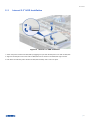
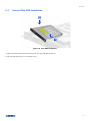
2-3 Internal 2.5’’ HDD Installation .......................................................................................... 21
2-4 Internal Slim ODD Installation .......................................................................................... 22
2-5 System Maintenance........................................................................................................ 23
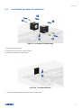
2-6 Fan Module Assembly & Installation ................................................................................ 24
2-7 PCIe Card Installation ....................................................................................................... 25
2-8 PSU Installation ................................................................................................................ 26
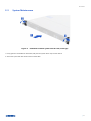
2-9 Slide Rail Installation......................................................................................................... 27
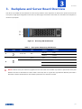
3. Backplane and Server Board Overview ........................................................................................ 29
3-1 Storage Backplane Option ................................................................................................ 30
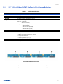
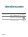
3-2 3.5” 4-Port 12Gbps SATA 7-Pin Port to Port Passive Backplane ......................................... 31
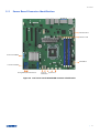
3-3 Server Board Connector Identification .............................................................................. 33
4. Maintenance and Service ............................................................................................................ 34

RB14604
│ 5
List of Figures
Figure 1 Overview .................................................................................................................................... 8
Figure 2 Major components overview ...................................................................................................... 8
Figure 3 Front panel ................................................................................................................................. 9
Figure 4 Back panel with 1U single PSU .................................................................................................. 10
Figure 5 Front control panel ................................................................................................................... 11
Figure 6 Chassis dimensions ................................................................................................................... 12
Figure 7 Label embossing dimensions .................................................................................................... 12
Figure 8 Front top cover installation ....................................................................................................... 17
Figure 9 Rear top cover installation ........................................................................................................ 17
Figure 10 3.5” hot-swap HDD assembly installation ................................................................................. 18
Figure 11 3.5” hot-swap HDD assembly removal ...................................................................................... 18
Figure 12 3.5” HDD installation (tool-less type) ........................................................................................ 19
Figure 13 3.5” HDD installation (screw type) ............................................................................................ 19
Figure 14 2.5” HDD/SSD installation in 3.5” tray (screw type)................................................................... 20
Figure 15 Internal 2.5'' HDD installation ................................................................................................... 21
Figure 16 Slim ODD installation ................................................................................................................ 22
Figure 17 Installation of whole system into the rack (screw type) ............................................................. 23
Figure 18 Fan module assembly (4028) .................................................................................................... 24
Figure 19 Air baffle installation ................................................................................................................ 24
Figure 20 Cards and brackets installation ................................................................................................. 25
Figure 21 1U single PSU installation-1 ...................................................................................................... 26
Figure 22 1U single PSU installation-2 ...................................................................................................... 26
Figure 23 Slide rail installation-1 (84H314610-003) .................................................................................. 27
Figure 24 Slide rail installation-2 (84H314610-003) .................................................................................. 27
Figure 25 Slide rail Installation-3 (84H314610-003) .................................................................................. 28
Figure 26 Slide rail Installation-4 (84H314610-003) .................................................................................. 28
Figure 27 Drive tray LED identification ..................................................................................................... 29
Figure 28 Backplane front view ................................................................................................................ 31
Figure 29 Backplane rear view ................................................................................................................. 32
Figure 30 Intel server board M10JNP2SB connector identification ........................................................... 33

RB14604
│ 6
List of Tables
Table 1 Chenbro RB14604 specifications .................................................................................................. 7
Table 2 RM14604 front control panel ..................................................................................................... 11
Table 3 Slide rail options ........................................................................................................................ 13
Table 4 System environmental specifications summary .......................................................................... 14
Table 5 System packing information ....................................................................................................... 15
Table 6 Product weight information ....................................................................................................... 15
Table 7 Drive power LED/activity LED behavior ...................................................................................... 29
Table 8 Backplane specifications ............................................................................................................ 31
Table 9 Connector and pin header function description ......................................................................... 32

RB14604
│ 7
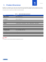
1. Product Overview
RB14604 is 1U cost effective server chassis, which supports Micro ATX motherboard and delivers flexible configurations for specific
applications. This chapter provides a high-level overview of the system features and available options. More details for each major
sub-system, feature, or options are provided in the following chapters.
Table 1 Chenbro RB14604 specifications
Feature
Description
MB Form Factor
Micro ATX (9.6” x 9.6”)
Dimension
(D x W x H)
547.6 x 438.5 x 43.5 (mm)
21.56’’ x 17.26’’ x 1.71’’
Drive Bay
4 x 3.5’’ Hot-swap, 2 x 2.5’’ Internal, 1 x Slim ODD (9.5 mm) ***
PSU Form Factor
1U Single
Indicator
1 x Power Status, 2 x LAN Activity, 1 x UID, 1 x System Alarm, 1 x HDD Status
Front Control
1 x Power On/Off, 1 x UID, 1 x Reset
Cooling Fan
40 x 28 mm (3)
System Security
N/A
Expansion Slot Opening
1 x Full Height & Half Length
Storage Backplane
3.5“ 4-port 12Gbps, SATA 7-pin
Net Weight
7.5 kg/16.52 lb
Gross Weight
10.0 kg/22.03 lb
Cubic Feet
1.84
Container Loading
20’:480, 40’:960
Note:
*** Internal 2.5” drives and Slim ODD with the thickness for 9.5 mm.

RB14604
│ 8
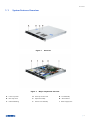
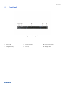
1-1 System Features Overview
Figure 1 Overview
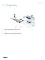
Figure 2 Major components overview
A. Front Top Cover
D. Rear Top Cover Latch
G. Fan Assembly
B. Rear Top Cover
E. Optical Drive Bay
H. Server Board
C. Label Embossing
F. Internal 2.5” HDD Bay
I. Power Supply Unit

RB14604
│ 9
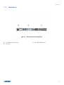
1-2 Front Panel
Figure 3 Front panel
A. Rack Handles
B. Storage Drive Bay
C. Optical Drive Bay
D. Info Tag
E. Front Control Panel
F. Storage Sticker

RB14604
│ 10
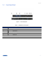
1-3 Back Panel
Figure 4 Back panel with 1U single PSU
A. 1U Single Power Supply Unit
B. I/O Gasket
C. Full Height Expansion Slot

RB14604
│ 11
1-4 Front Control Panel
Figure 5 Front control panel
Table 2 RB14604 front control panel
Label
ICON
Indicator, button or connector
A
Power Button/LED
B
HDD Activity LED
C
System Alarm LED
D
LAN1, LAN2 Activity LED
E
Reset Button
F
UID Button/LED
G
USB3.0
H
Rack Handle (Screw Type)

RB14604
│ 12
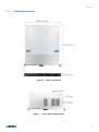
1-5 Chassis Dimensions
Figure 6 Chassis dimensions
Figure 7 Label embossing dimensions

RB14604
│ 13
1-6 Available Rack Mounting Kit Options (Refer to “Installation”)
Advisory Note – Available rack and cabinet mounting kits are not designed to support shipment of the server system while installed
in a rack. If you choose to do so, Chenbro advises you verify your shipping configuration with appropriate shock and vibration testing
before shipment. Chenbro does not perform shipping tests which cover the complex combination of unique rack offerings and custom
packaging options.
Caution: Exceeding the specified maximum weight limit of a given rail kit or misalignment of the server in the rack may result in
failure of the rack rails, causing damage to the system or personal injury. More than one person to operate with mechanical assist
tools to install and align the server into the rack is highly recommended.
Available rack mounting kits:
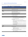
Table 3 Slide rail options
Part Number
84H314610-003
Rail Dimension (mm/inch)
599.0/23.60"
Applicable Cabinet Post to Post (mm/inch)
660.0~838.0/26.00"~33.00"
Sliding Mode
Ball-bearing, 2 section
Traveling Distance (mm/inch)
560.0/22.00"
Support Chassis Width (mm)
438.5
Loading (kg)
15.0
Max. Static Loading (kg) for UL
61.9
Tool-less
Yes
Support CMA
No

RB14604
│ 14
1-7 System Level Environmental Specifications
The following table defines the system level specifications under operating and non-operating environments.
Table 4 System environmental specifications summary
Parameter
Specification
Temperature
Operating
5º C to 35º C (41º F to 95º F)
Temperature
Non-Operating
-40º C to 70º C (-40ºF to 158º F)
Humidity
Non-Operating
50% to 90%, non-condensing with a maximum wet bulb of 28° C (at
temperatures from 25° C to 35° C)
Unpackaged
Shock
Non-Operating
Trapezoidal, 25 g, velocity change is based on product weight
Unpackaged
Vibration
Operating
5 Hz @ 0.0002 g2/Hz to 350 Hz @ 0.0002 g2/Hz
Input acceleration is 0.26 g RMS
10 minutes per axis for all 3 axes on all samples
Random control limit tolerance is ± 3 dB
Sag & Bow
Non-Operating
Tolerance analysis among rack, rail and chassis
Actual on rack test with EIA Go-NoGo fixture
EMI
Pre-Scan
Radiated Emissions
CISPR Class A (under 6 dB):
30~1000 MHz vertical/horizontal
1G~6G GHz vertical/horizontal
1G~18G GHz vertical/horizontal
ESD
Contact and Air Discharge
Electrostatic Discharge Immunity Test IEC 61000-4-2
RVI
Operating
HDD Class:
Class 1: Highest performance, reliability, and data integrity
Class 2: A second tier of performance, reliability, and data integrity
HDD I/O throughput degradation SPEC
Pass/Fail Criteria
No functional failure during test or post-test diagnostics
Requirement to pass test is based on IOMeter data throughput (in IO’s
per second) expressed as a percent of Test HDD maximum theoretical
baseline performance
Class1: > 90% of baseline for 4K Random Writes and > 80% of baseline
for 128K Sequential Writes
Class2: > 85% of baseline for 4K Random Writes and > 75% of baseline
for 128K Sequential Writes
Mix: > 80% of baseline for 4K Random Writes and > 70% of baseline for
128K Sequential Writes
Packaged
Vibration
Non-Operating
ISTA (weight over 68.0 kg, 1B; weight equal or less than 68.0 kg, 1A)
Packaged
Drop
Non-Operating
Drop height change is based on product weight
Non-palletized product:
Investigation: Test requirement is with 6 face drops, 8 corner drops and
12 edge drops for total 26 drops
Validation: Test requirement is with 6 face drops, 2 corner drops and 3
edge drops for a total 11 drops
Palletized product: (both investigation and validation)
Perform 2 bottom drops at the specified height, 10 bottom drops at one
half of the specified height
Perform 4 rotational edge drops (one per edge) at the specified height

RB14604
│ 15
1-8 System Packaging
The original Chenbro packaging, where the server system is delivered, is designed to provide protection for L6 configuration and
tested to meet ISTA (International Safe Transit Association) Test Procedure 1A (2008). The packaging is also designed to be reused
for shipment after system integration has been completed.
The original packaging includes the shipping box and various protective inner packaging components, which are designed to as a
protective packaging system. When reused, all the original packaging materials must be included such as boxes and each inner
packaging component. In addition, all inner packaging components MUST be reinstalled in the proper location to ensure adequate
protection of the system for subsequent shipment.
Table 5 System packing information
Part Number
Single/Bulk
Form Factor
Support Level
87H314604-302
Single
670 x 556 x 140
L6
NOTE: The design of the inner packaging components does not prevent improper placement within the packaging assembly.
There is only one correct packaging assembly that will allow the package to meet the ISTA (International Safe Transit Association)
Test Procedure 1A (2008).
Failure to follow the specified packaging assembly instructions may result in damage to the system during shipment.
Table 6 Product weight information
Product
Unpackaged Net Weight
(kg)
Packaged Gross Weight
(kg)
Unpackaged Net Weight
(lb)
Packaged Gross Weight
(lb)
RB14604
8.2
10.3
18.10
22.70
NOTE: An L6 system includes MB without processors, memory, drives, or add-in cards. It is the system configuration as
shipped from Chenbro. Weights of integrated system (system configurations that include the items above) will vary
depending on the final system configuration.

RB14604
│ 16
2. System Components Removal and Installation
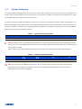
RB14604 supports for the following storages:
Up to 4 x 3.5” hot swap SAS/SATA HDD
2 x 2.5" internal HDD or SSD up to 9.5 mm thickness
Support for different storage and peripheral options will vary depending on the system model and/or available accessory options
installed.

RB14604
│ 17
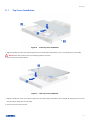
2-1 Top Cover Installation
Figure 8 Front top cover installation
1. Align the guide pins of this cover with the grooves on the chassis base, and slide the cover in (two guide pins for both sides).
NOTE: Ensure that arrows on the cover indicating the back of chassis.
2. Secure it with two screws as shown.
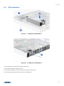
Figure 9 Rear top cover installation
1. Align the guide pins of this cover with the grooves on the chassis base, and slide the cover towards the front panel until it locks
into place (three guide pins for both sides).
2. Secure it with one screw as shown.

RB14604
│ 18
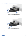
2-2 Hot-swap HDD Assembly Removal and Installation
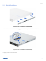
Figure 10 3.5” hot-swap HDD assembly installation
1. With the open lever, insert the HDD assembly into the drive bay until the end of HDD cage.
2. Push in the lever when it is secured with a click.
Figure 11 3.5” hot-swap HDD assembly removal
1. Press the tray button, and release the lever as shown.
2. Pull the HDD assembly out of the drive bay.

RB14604
│ 19
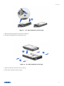
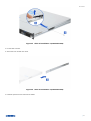
Figure 12 3.5” HDD installation (tool-less type)
1. Slide in the HDD until align the anchor point of HDD tray.
2. Push down the HDD when it is secured with a click.
Figure 13 3.5” HDD installation (screw type)
1. Align front HDD with the anchor point on the tray.
2. Fasten the tray with four screws as shown.

RB14604
│ 20
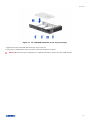
Figure 14 2.5” HDD/SSD installation in 3.5” tray (screw type)
1. Align the front of the HDD/SSD with the anchor point on the tray.
2. Secure the 2.5” HDD/SSD into the tray by three screws from the bottom as shown.
NOTE: Dedicated screw type is required for 2.5” HDD/SSD Installation, Chenbro P/N: 384-14602-3143A0.
La pagina si sta caricando...
La pagina si sta caricando...
La pagina si sta caricando...
La pagina si sta caricando...
La pagina si sta caricando...
La pagina si sta caricando...
La pagina si sta caricando...
La pagina si sta caricando...
La pagina si sta caricando...
La pagina si sta caricando...
La pagina si sta caricando...
La pagina si sta caricando...
La pagina si sta caricando...
La pagina si sta caricando...
-
 1
1
-
 2
2
-
 3
3
-
 4
4
-
 5
5
-
 6
6
-
 7
7
-
 8
8
-
 9
9
-
 10
10
-
 11
11
-
 12
12
-
 13
13
-
 14
14
-
 15
15
-
 16
16
-
 17
17
-
 18
18
-
 19
19
-
 20
20
-
 21
21
-
 22
22
-
 23
23
-
 24
24
-
 25
25
-
 26
26
-
 27
27
-
 28
28
-
 29
29
-
 30
30
-
 31
31
-
 32
32
-
 33
33
-
 34
34


in altre lingue
- English: Chenbro RB14604 User manual
Altri documenti
-
DeLOCK 82660 Scheda dati
-
-
DeLOCK 47194 Scheda dati
-
DeLOCK 47229 Scheda dati
-
-
Tyan YR188-B537M Manuale utente
-
-
-
Intel SR1625UR - Server System - 0 MB RAM Manuale utente
-