Gigabyte GA-IMBLAP3455 Manuale del proprietario
- Categoria
- Schede madri
- Tipo
- Manuale del proprietario

GA-IMBLAP3455
User's Manual
Rev. 1001
To reduce the impacts on global warming, the packaging materials of this product
are recyclable and reusable. GIGABYTE works with you to protect the environment.
For more product details, please visit GIGABYTE's website.

- 2 -
Copyright
© 2020 GIGA-BYTE TECHNOLOGY CO., LTD. All rights reserved.
The trademarks mentioned in this manual are legally registered to their respective owners.
Disclaimer
Information in this manual is protected by copyright laws and is the property of GIGABYTE.
Changes to the specications and features in this manual may be made by GIGABYTE without
prior notice.
No part of this manual may be reproduced, copied, translated, transmitted, or published in any form
or by any means without GIGABYTE's prior written permission.
In order to assist in the use of this product, carefully read the User's Manual.
For product-related information, check on our website at: https://www.gigabyte.com
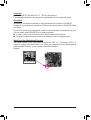
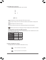
Identifying Your Motherboard Revision
The revision number on your motherboard looks like this: "REV: X.X." For example, "REV: 1.0"
means the revision of the motherboard is 1.0. Check your motherboard revision before updating
motherboard BIOS, drivers, or when looking for technical information.
Example:

- 3 -
Table of Contents
GA-IMBLAP3455 Motherboard Layout ............................................................................ 4
Chapter 1 Hardware Installation .....................................................................................5
1-1 Installation Precautions .................................................................................... 5
1-2 Product Specications ...................................................................................... 6
1-3 Installing the Memory ....................................................................................... 8
1-4 Installing an Expansion Card ........................................................................... 8
1-5 Back Panel Connectors .................................................................................... 8
1-6 Internal Connectors ........................................................................................ 10
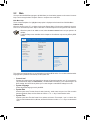
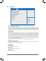
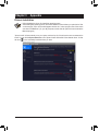
Chapter 2 BIOS Setup ..................................................................................................22
2-1 Startup Screen ............................................................................................... 22
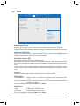
2-2 Main ............................................................................................................... 23
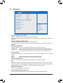
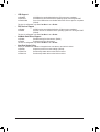
2-3 Advanced ....................................................................................................... 24
2-4 Security .......................................................................................................... 28
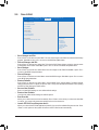
2-5 Boot ................................................................................................................ 30
2-6 Save & Exit ..................................................................................................... 32
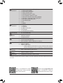
Chapter 3 Appendix ......................................................................................................33
Drivers Installation ..................................................................................................... 33
Regulatory Notices .................................................................................................... 34
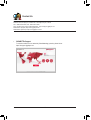
Contact Us ................................................................................................................ 35

- 4 -
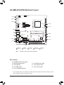
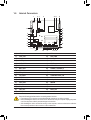
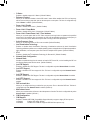
GA-IMBLAP3455 Motherboard Layout
* The box contents above are for reference only and the actual items shall depend on the product package you obtain.
The box contents are subject to change without notice.
(Note) This chip is on the back of the motherboard.
GA-IMBLAP3455
DC_PWR
ATX_12V LVDS
SATA_PWR
M_BIOS
SYS_FAN
PCIEX1
FPD_PWR
FPD
CLR_CMOS
DMIC_CON
F_AUDIO
BAT_CON F_PANEL
BL_SW
CI
LCD_VCC
COMB
MON_SW
RUSB30_2
RUSB30_1
Intel® Apollo Lake SoC J3455E
SPEAKER
LPT_GPIO
COMD COMF
FUSB20_1
BAT
MIC_IN
COMA COMC
MINI_PCIE
SATA3
M.2
LINE_OUT CODEC
SPKR
iTE®
Super I/O (Note)
HDMI
LAN1
LAN2
Realtek® GbE LAN
SODIMM_2
SODIMM_1
COME
Realtek® GbE LAN
VGA
VGA_CONN
60 CPU_FAN
SMBUS
FUSB20_2
0
1
42
I2C
COMA_PW COMB_PW COMC_PW COMD_PW COME_PW
COMF_PW GPIO_SET BIOS_SET GPIO_PWRSEL LPT_SEL
B_BIOS (Note)
Box Contents
5GA-IMBLAP3455 motherboard
5Motherboard driver disc 5One SATA power cable
5User's Manual 5One COM port cable
5Two SATA cables 5One LPT port cable
5Two I/O Shields (high/low)

- 5 -
Chapter 1 Hardware Installation
1-1 Installation Precautions
The motherboard contains numerous delicate electronic circuits and components which can become
damaged as a result of electrostatic discharge (ESD). Prior to installation, carefully read the user's
manual and follow these procedures:
•Prior to installation, make sure the chassis is suitable for the motherboard.
•Prior to installation, do not remove or break motherboard S/N (Serial Number) sticker or
warranty sticker provided by your dealer. These stickers are required for warranty validation.
•Always remove the AC power by unplugging the power cord from the power outlet before
installing or removing the motherboard or other hardware components.
•When connecting hardware components to the internal connectors on the motherboard, make
sure they are connected tightly and securely.
•When handling the motherboard, avoid touching any metal leads or connectors.
•It is best to wear an electrostatic discharge (ESD) wrist strap when handling electronic
components such as a motherboard, CPU or memory. If you do not have an ESD wrist strap,
keep your hands dry and rst touch a metal object to eliminate static electricity.
•Prior to installing the motherboard, please have it on top of an antistatic pad or within an
electrostatic shielding container.
•Before connecting or unplugging the power supply cable from the motherboard, make sure
the power supply has been turned off.
•Before turning on the power, make sure the power supply voltage has been set according to
the local voltage standard.
•Before using the product, please verify that all cables and power connectors of your hardware
components are connected.
•To prevent damage to the motherboard, do not allow screws to come in contact with the
motherboard circuit or its components.
•Make sure there are no leftover screws or metal components placed on the motherboard or
within the computer casing.
•Do not place the computer system on an uneven surface.
•Do not place the computer system in a high-temperature or wet environment.
•Turning on the computer power during the installation process can lead to damage to system
components as well as physical harm to the user.
•If you are uncertain about any installation steps or have a problem related to the use of the
product, please consult a certied computer technician.
•If you use an adapter, extension power cable, or power strip, ensure to consult with its installation
and/or grounding instructions.

- 6 -
1-2 ProductSpecications
CPU Built in with an Intel® Quad-Core Celeron® J3455E SoC (2.3 GHz)
* Do not disassemble the onboard SoC and the heatsinks by yourself to avoid damage
to these components.
2 MB Cache
Memory 2 x DDR3L SO-DIMM sockets supporting up to 16 GB of system memory
Dual channel memory architecture
Support for DDR3L 1866/1600 MHz memory module
(Go to GIGABYTE's website for the latest supported memory speeds and memory
modules.)
Onboard
Graphics
Integrated in the SoC:
- 1 x D-Sub port, supporting a maximum resolution of 1920x1200@60 Hz
- 1 x HDMI port, supporting a maximum resolution of 3840x2160@30 Hz
Maximum shared memory of 512 MB
Audio Realtek® ALC887codec
High Denition Audio
2/4/5-channel
LAN 2 x Realtek® GbE LAN chips (1000/100 Mbit)
Expansion Slots 1 x PCI Express x1 slot
1 x Mini PCIe slot (MINI_PCIE)
(The PCIe Express x1 and Mini PCIe slots conform to PCI Express 2.0 standard.)
Storage Interface Integrated in the SoC:
- 2 x SATA 6Gb/s connectors
- 1 x M.2 connector (Socket 3, M key, type 2242/2260 SATA and PCIe x1 SSD
support)
* Refer to "1-6 Internal Connectors," for the installation notices for the M.2 and SATA
connectors.
USB Integrated in the SoC:
- 4 x USB 3.1 Gen 1 ports on the back panel
- 4 x USB 2.0/1.1 ports available through the internal USB headers
Internal
Connectors
1 x 4-pin ATX 12V power connector
1 x CPU fan header
1 x system fan header
2 x SATA 6Gb/s connectors
1 x M.2 Socket 3 connector
1 x SATA power connector
1 x front panel header
1 x front panel audio header
1 x battery cable header
2 x USB 2.0/1.1 headers
6 x serial port headers
6 x serial port power select jumpers
1 x D-Sub header
1 x LVDS header
1 x LVDS drive voltage jumper (LCD_VCC)
1 x at panel display header (FPD)
1 x at panel display power select jumper (FPD_PWR)
1 x at panel display switch header (MON_SW)
1 x backlight switch header (BL_SW)

- 7 -
Internal
Connectors
1 x digital microphone header (DMIC_CON)
1 x speaker header (SPKR)
1 x buzzer header (SPEAKER)
1 x chassis intrusion jumper
1 x LPT/GPIO header (LPT_GPIO)
1 x LPT conguration jumper (LPT_SEL)
1 x GPIO power selection jumper (GPIO_PWRSEL)
1 x GPIO status conguration jumper (GPIO_SET)
1 x BIOS Select jumper (BIOS_SET)
1 x Clear CMOS jumper
1 x I2C
1 x SMBUS
Back Panel
Connectors
1 x DC-In power connector
1 x HDMI port
1 x D-Sub port
4 x USB 3.1 Gen 1 ports
2 x RJ-45 ports
2 x audio jacks (Line In, Mic In)
I/O Controller iTE® I/O Controller Chip
Hardware
Monitor
Voltage detection
Temperature detection
Fan speed detection
BIOS 2 x 64 Mbit ash
Use of licensed AMI UEFI BIOS
PnP 1.0a, DMI 2.7, WfM 2.0, SM BIOS 2.7, ACPI 5.0
Unique Features Support for Xpress Install
Support for @BIOS
Support for APP Center
* Available applications in APP Center may vary by motherboard model. Supported
functions of each application may also vary depending on motherboard specications
Bundled
Software Norton® Internet Security (OEM version)
Operating
System Support for Windows 10 64-bit
Form Factor Thin Mini-ITX Form Factor; 17.0cm x 17.0cm
* GIGABYTE reserves the right to make any changes to the product specications and product-related information without
prior notice.
Please visit GIGABYTE's website
for support lists of memory modules,
SSDs, and M.2 devices..
Please visit the Support\Utility List
page on GIGABYTE's website to
download the latest version of apps.

- 8 -
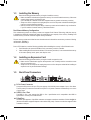
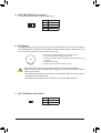
1-3 Installing the Memory
Read the following guidelines before you begin to install the memory:
•Make sure that the motherboard supports the memory. It is recommended that memory of the same
capacity, brand, speed, and chips be used.
(Go to GIGABYTE's website for the latest supported memory speeds and memory modules.)
•Always turn off the computer and unplug the power cord from the power outlet before installing the
memory to prevent hardware damage.
•Memory modules have a foolproof design. A memory module can be installed in only one direction.
If you are unable to insert the memory, switch the direction.
1-4 Installing an Expansion Card
Read the following guidelines before you begin to install an expansion card:
•Make sure the motherboard supports the expansion card. Carefully read the manual that came
with your expansion card.
•Always turn off the computer and unplug the power cord from the power outlet before installing an
expansion card to prevent hardware damage.
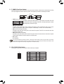
1-5 Back Panel Connectors
DualChannelMemoryConguration
This motherboard provides two memory sockets and supports Dual Channel Technology. After the memory
is installed, the BIOS will automatically detect the specications and capacity of the memory. Enabling Dual
Channel memory mode will double the original memory bandwidth.
The two memory sockets are divided into two channels and each channel has one memory socket as following:
Channel A: SODIMM_1
Channel B: SODIMM_2
Due to CPU limitations, read the following guidelines before installing the memory in Dual Channel mode.
1. Dual Channel mode cannot be enabled if only one memory module is installed.
2. When enabling Dual Channel mode with two or four memory modules, it is recommended that memory
of the same capacity, brand, speed, and chips be used.
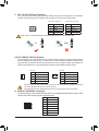
DC In Power Connector
Connect the DC power to this port. This port supports 12V/19V/24V power adapter of up to 150w. Note:
The DC power jack cannot be used with the 4-pin ATX 12V power connector simultaneously as a source
of power input.
USB 3.1 Gen 1 Port
The USB 3.1 Gen 1 port supports the USB 3.1 Gen 1 specication and is compatible to the USB 2.0
specication. Use this port for USB devices.
D-Sub Port
The D-Sub port supports a 15-pin D-Sub connector and supports a maximum resolution of 1920x1200@60 Hz
(the actual resolutions supported depend on the monitor being used). Connect a monitor that supports D-Sub
connection to this port.

- 9 -
Line Out
The line out jack. Use this audio jack for a headphone or 2-channel speaker. This jack can be used to
connect front speakers in a 4/5.1-channel audio conguration.
Mic In
The Mic in jack.
•When removing the cable connected to a back panel connector, rst remove the cable from
your device and then remove it from the motherboard.
•When removing the cable, pull it straight out from the connector. Do not rock it side to side to
prevent an electrical short inside the cable connector.
Please visit GIGABYTE's website for more software information.
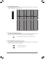
Activity LEDConnection/
Speed LED
LAN Port Connection/Speed LED:
State Description
Orange 1 Gbps data rate
Green 100 Mbps data rate
Off 10 Mbps data rate
Activity LED:
State Description
Blinking Data transmission or receiving is occurring
Off No data transmission or receiving is occurring
RJ-45 LAN Port
The Gigabit Ethernet LAN port provides Internet connection at up to 1 Gbps data rate. The following
describes the states of the LAN port LEDs.
HDMI Port
The HDMI port is HDCP compliant and supports Dolby TrueHD and DTS HD
Master Audio formats. It also supports up to 192KHz/24bit 7.1-channel LPCM
audio output. You can use this port to connect your HDMI-supported monitor. The maximum supported
resolution is 3840x2160@30 Hz, but the actual resolutions supported are dependent on the monitor being
used.
After installing the HDMI device, make sure to set the default sound playback device to HDMI. (The
item name may differ depending on your operating system.)
Dual-DisplayCongurationsfortheOnboardGraphics:
Dual-display congurations are supported after you install motherboard drivers in OS.

- 10 -
Read the following guidelines before connecting external devices:
•First make sure your devices are compliant with the connectors you wish to connect.
•Before installing the devices, be sure to turn off the devices and your computer. Unplug the power
cord from the power outlet to prevent damage to the devices.
•After installing the device and before turning on the computer, make sure the device cable has
been securely attached to the connector on the motherboard.
1-6 Internal Connectors
1) ATX_12V
2) CPU_FAN
3) SYS_FAN
4) SATA3_0/1
5) SATA_PWR
6) BAT
7) BAT_CON
8) F_PANEL
9) VGA_CONN
10) LPT_GPIO
11) LPT_SEL
12) GPIO_PWRSEL
13) GPIO_SET
14) LVDS
15) BL_SW
16) LCD_VCC
17) MON_SW
18) FPD
19) FPD_PWR
20) DMIC_CON
21) F_AUDIO
22) SPKR
23) SPEAKER
24) FUSB20_1/FUSB20_2
25) COMA/COMB/COME/COMF
26) COMC/COMD
27) COMA/B/C/D/E/F_PW
28) CI
29) CLR_CMOS
30) SMBUS
31) I2C
32) M.2
33) BIOS_SET
23
20
3
8
16
10
15
1
6
7
22
21
30
24
4
19
18
9
25 26 25
27 33 12
11
28
2
145
13
1731
29
32

- 11 -
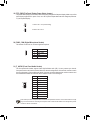
4) SATA3 0/1 (SATA 6Gb/s Connectors)
The SATA connectors conform to SATA 6Gb/s standard and are compatible with SATA 3Gb/s and SATA 1.5Gb/s
standard. Each SATA connector supports a single SATA device.
DEBUG
PORT
G.QBOFM
17
DEBUG
PORT
G.QBOFM
17
Pin No. Denition
1 GND
2 TXP
3 TXN
4 GND
5 RXN
6 RXP
7 GND
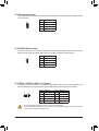
2/3) CPU_FAN/SYS_FAN (Fan Headers)
The fan headers on this motherboard are 4-pin. Most fan headers possess a foolproof insertion design.
When connecting a fan cable, be sure to connect it in the correct orientation (the black connector wire is
the ground wire). The speed control function requires the use of a fan with fan speed control design. For
optimum heat dissipation, it is recommended that a system fan be installed inside the chassis.
CPU_FAN: SYS_FAN:
Pin No. Denition
1 GND
2 Speed Control
3 Sense
4 VCC
•Be sure to connect fan cables to the fan headers to prevent your CPU and system from overheating. Overheating
may result in damage to the CPU or the system may hang.
•These fan headers are not conguration jumper blocks. Do not place a jumper cap on the headers.
Pin No. Denition
1 GND
2 +12V
3 Sense
4 Speed Control
SYS_FAN
DEBUG
PORT
G.QBOFM
1
CPU_FAN
DEBUG
PORT
G.QBOFM
1
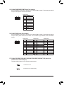
1) ATX_12V (2x2 12V Power Connector)
This connector can be used to input power when the DC power jack on the rear panel is not connected.
However, if the DC power jack is connected, this connector can only be used to output power.
When used to input power:
Pin No. Denition
1 GND
2 GND
3 +12V
4 +12V
3
Note: The two connectors cannot be used simultaneously as a source of power input.
or
HDD LED
RESET SW
HDD LED
RESET SW
with
HDD LED
RESET SW
HDD LED
RESET SW
ar
When used to output power:
Pin No. Denition
1 GND
2 GND
3 DC_OUT
4 DC_OUT
4
1
2

- 12 -
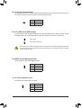
5) SATA_PWR (SATA Power Connector)
This connector provides power to installed SATA devices.
Pin No. Denition
1 VCC
2 GND
3 GND
4 +12V
eDP
1
6) BAT (Battery)
The battery provides power to keep the values (such as BIOS congurations, date, and time information)
in the CMOS when the computer is turned off. Replace the battery when the battery voltage drops to a low
level, or the CMOS values may not be accurate or may be lost.
You may clear the CMOS values by removing the battery cable:
1. Turn off your computer and unplug the power cord.
2. Unplug the the battery cable from the battery cable header and wait for
one minute.
3. Plug in the battery cable.
4. Plug in the power cord and restart your computer.
•Always turn off your computer and unplug the power cord before replacing the battery.
•Replace the battery with an equivalent one. Damage to your devices if the battery is replaced
with an incorrect model.
•Contact the place of purchase or local dealer if you are not able to replace the battery by yourself
or uncertain about the battery model.
•Used batteries must be handled in accordance with local environmental regulations.
7) BAT_CON (Battery Cable Header)
Pin No. Denition
1(+) RTC Power
2(-) GND
1(+) 2(-)

- 13 -
8) F_PANEL (Front Panel Header)
Connect the power switch, reset switch, and system status indicator on the chassis to this header according
to the pin assignments below. Note the positive and negative pins before connecting the cables.
1
2
9
10
NC
PLED-
PW-
PLED+
PW+
HD-
RES+
HD+
RES-
Power Switch
Hard Drive
Activity LED
Reset Switch
Power LED
The front panel design may differ by chassis. A front panel module mainly consists of power switch, reset switch,
power LED, hard drive activity LED and etc. When connecting your chassis front panel module to this header, make
sure the wire assignments and the pin assignments are matched correctly.
•PW (Power Switch, Red):
Connects to the power switch on the chassis front panel. You may congure the way to turn off your
system using the power switch (refer to Chapter 2, "BIOS Setup," "Power," for more information).
•HD (Hard Drive Activity LED, Blue):
Connects to the hard drive activity LED on the chassis front panel. The LED is on when the hard drive
is reading or writing data.
•RES (Reset Switch, Lake Green):
Connects to the reset switch on the chassis front panel. Press the reset switch to restart the computer
if the computer freezes and fails to perform a normal restart.
•NC (Purple):
No connection.
•PLED (Power LED, Grass Green):
Connects to the power status indicator on the chassis front panel. The LED
is on when the system is operating. The LED is off when the system is in S3/
S4 sleep state or powered off (S5).
System Status LED
S0 On
S3/S4/S5 Off
9) VGA_CONN (D-Sub Header)
This header can be used to connect a D-Sub monitor by an adapter.
Pin No. Denition Pin No. Denition
1 VGA_R 6 GND
2 GND 7 HSYNC
3 VGA_G 8 VSYNC
4 GND 9 VGA_SCL
5 VGA_B 10 VGA_SDA
10
eDP
9
21

- 14 -
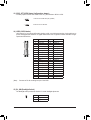
10) LPT_GPIO (LPT/GPIO Header)
Use this header to connect a LPT or GPIO device. Refer to the descriptions of the LPT_SEL and GPIO_
PWRSEL jumpers below for further conguration.
Pin No. Denition Pin No. Denition Pin No. Denition
1STB- 10 GND 19 ACK-
2AFD- 11 PD4 20 GND
3PD0 12 GND 21 BUSY
4ERR- 13 PD5 22 GND
5PD1 14 GND 23 PE
6INIT- 15 PD6 24 GND
7PD2 16 GND 25 SLCT
8SLIN- 17 PD7 26 No Pin
9PD3 18 GND
LPT:
Pin No. Denition Pin No. Denition Pin No. Denition
1SIO_GP87 10 GPIOPWR 19 SIO_GP83
2SIO_GP86 11 SIO_GP74 20 GND
3SIO_GP70 12 GPIOPWR 21 SIO_GP82
4NC 13 SIO_GP75 22 GND
5SIO_GP71 14 GND 23 SIO_GP81
6SIO_GP85 15 SIO_GP76 24 GND
7SIO_GP72 16 GND 25 SIO_GP80
8SIO_GP84 17 SIO_GP77 26 No Pin
9SIO_GP73 18 GND
GPIO:
11) LPT_SEL(LPTCongurationJumper)
Place the jumper cap on the two pins to congure the LPT_GPIO header to support LPT device. Note: If
the jumper cap is removed from this jumper, be sure to place it on the GPIO_PWRSEL pins.
Short: Congure the LPT_GPIO header to support LPT device. (Default)
1
eDP
26 25
2 1
12) GPIO_PWRSEL (GPIO Power Selection Jumper)
Move the jumper cap from the LPT_SEL jumper to this jumper to congure the LPT_GPIO header to support
GPIO device and also to specify the GPIO voltage.
1-2 Close: Set GPIO voltage to +12V.
2-3 Close: Set GPIO voltage to 5V.
1
1

- 15 -
13) GPIO_SET(GPIOStatusCongurationJumper)
Use this jumper to set the GPIO status of the LPT_GPIO header to HIGH or LOW.
1-2 Close: Set to HIGH level (3V) (Default)
2-3 Close: Set to LOW level.
1
1
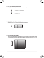
14) LVDS (LVDS Header)
LVDS stands for Low-voltage differential signaling, which uses high-speed analog circuit techniques to
provide multigigabit data transfers on copper interconnects and is a generic interface standard for high-
speed data transmission.
Pin No. Denition Pin No. Denition
1 LCD_VCC 21 -RXE0_C
2 LCD_VCC 22 +RXE0_C
3 VCC3 23 GND
4 NC 24 -RXE1_C
5 NC 25 +RXE1_C
6 -RXO0_C 26 GND
7 +RXO0_C 27 -RXE2_C
8 GND 28 +RXE2_C
9 -RXO1_C 29 CABLE_DET (Note)
10 +RXO1_C 30 -RXE3_C
11 GND 31 +RXE3_C
12 -RXO2_C 32 GND
13 +RXO2_C 33 -RXECLKE_C
14 GND 34 +RXECLKE_C
15 -RXO3_C 35 GND
16 +RXO3_C 36 SC_BKLT_EN
17 GND 37 SC_BKLT_CTL
18 -RXECLKO_C 38 FPD_PWR
19 +RXECLKO_C 39 FPD_PWR
20 GND 40 FPD_PWR
(Note) Connects to Pin 29 and the ground pin of the LVDS.
eDP
2 1
40 39
15) BL_SW (Backlight Switch)
The Backlight switch provides the function for screen backlight adjustment.
Pin No. Denition
1 BL_DOWN
2 BL_UP
1

- 16 -
16) LCD_VCC (LVDS Drive Voltage Jumper)
This jumper can be used to provide different screen voltage settings.
1-2 Close: Set to 3V. (Default setting)
2-3 Close: Set to 5V.
1
1
17) MON_SW (Flat Panel Display Switch Header)
This header allows you to connect an on/off switch for the LVDS display.
Pin No. Denition
1 Mon_SW
2 GND
1
18) FPD (Flat Panel Display Header)
The FPD is a high-speed interface connecting the output of a video controller in a laptop computer, computer
monitor or LCD television set to the display panel. Most laptops, LCD computer monitors and LCD TVs use
this interface internally. The header conforms to FPD specication.
Pin No. Denition
1 BKLT_EN
2 BKLT_PWM
3 BKLT_PWR (FPD_PWR)
4 BKLT_PWR (FPD_PWR)
5 BKLT_GND/Brightness_GND
6 BKLT_GND/Brightness_GND
7 Brightness_Up
8 Brightness_Down
1
8
eDP

- 17 -
19) FPD_PWR (Flat Panel Display Power Select Jumper)
The power select jumper can be used to select the working voltage of the at panel display. Make use your at
panel display supports DC In power. If not, use a DC In power adapter that meets the voltage requirements
of your at panel display.
1-2 Close: Set to 12V. (Default setting)
2-3 Close: Set to DC In.
1
1
Pin No. Denition
1 VCC
2 DMIC_DATA
3 GND
4 DMIC_CLK
DEBUG
PORT
G.QBOFM
1
20) DMIC_CON (Digital Microphone Header)
This header can be used to connect a digital microphone.
21) F_AUDIO (Front Panel Audio Header)
The front panel audio header supports Intel® High Denition audio (HD). You may connect your chassis
front panel audio module to this header. Make sure the wire assignments of the module connector match
the pin assignments of the motherboard header. Incorrect connection between the module connector and
the motherboard header will make the device unable to work or even damage it.
Pin No. Denition
1 MIC2_L
2 GND
3 MIC2_R
4 NC
5 LINE2_R
6 Sense
7 FAUDIO_JD
8 No Pin
9 LINE2_L
10 Sense
Some chassis provide a front panel audio module that has separated connectors on each wire instead of a single
plug. For information about connecting the front panel audio module that has different wire assignments, please
contact the chassis manufacturer.
1
2
9
10

- 18 -
22) SPKR (Speaker Header)
This header connects to the L/R Audio output of the motherboard and supports 3W stereo speaker (4 Ohm)
in an AIO chassis.
1
4
eDP
Pin No. Denition
1 Speaker OUT R-
2 Speaker OUT R+
3 Speaker OUT L-
4 Speaker OUT L+
23) SPEAKER (Buzzer Header)
Connects to the buzzer on the chassis front panel. The system reports system startup status by issuing a
beep code. One single short beep will be heard if no problem is detected at system startup.
Pin No. Denition
1 VCC
2 NC
3 NC
4 SPK-
DEBUG
PORT
G.QBOFM
1
24) FUSB20_1/FUSB20_2 (USB 2.0/1.1 Headers)
The headers conform to USB 2.0/1.1 specication. Each USB header can provide two USB ports via an
optional USB bracket. For purchasing the optional USB bracket, please contact the local dealer.
Pin No. Denition Pin No. Denition
1 Power (5V) 6 USB DY+
2 Power (5V) 7 GND
3 USB DX- 8 GND
4 USB DY- 9 No Pin
5 USB DX+ 10 NC
•Do not plug the IEEE 1394 bracket (2x5-pin) cable into the USB header.
•Prior to installing the USB bracket, be sure to turn off your computer and unplug the power cord from the power
outlet to prevent damage to the USB bracket.
210
91

- 19 -
25) COMA/COMB/COME/COMF (Serial Port Headers)
Each COM header can provide one serial port via an optional COM port cable. For purchasing the optional
COM port cable, please contact the local dealer.
10
eDP
9
2
1Pin No. Denition
1 NDCD-
2 NDSR-
3 NSIN
4 NRTS-
5 NSOUT
6NCTS-
7 NDTR-
8 +5V/+12V
9 GND
10 NC
RS232 device:
26) COMC/COMD (Serial Port Headers)
Each COM header can provide one serial port via an optional COM port cable. For purchasing the optional
COM port cable, please contact the local dealer. The two headers support RS232, RS422, and RS485
devices.
10
eDP
9
2
1Pin No. Denition
1 NDCD-
2 NDSR-
3 NSIN
4 NRTS-
5 NSOUT
6 NCTS-
7 NDTR-
8 +5V/+12V
9 GND
10 NC
RS232 device:
Pin No. Denition
1 TX(B)
2 NC
3 TX(A)
4 NC
5 RX(A)
6 NC
7 RX(B)
8 +5V/+12V
9 GND
10 NC
RS422 device:
Pin No. Denition
1 D-
2 NC
3 D+
4 NC
5 NC
6 NC
7 NC
8 +5V/+12V
9 GND
10 NC
RS485 device:
27) COMA_PW/COMB_PW/COMC_PW/COMD_PW/COME_PW/COMF_PW (Serial Port
Header Power Select Jumpers)
The power select jumpers are used to select serial port power.
1-2 Close: Set to 12V.
2-3 Close: Set to 5V. (Default setting)
1
1

- 20 -
30) SMBUS (System Management Bus)
Use this header to read/control SMBUS signals.
Pin No. Denition
1 SMB_CLK
2 SMB_DATA
3 GND
1
28) CI (Chassis Intrusion Header)
This motherboard provides a chassis detection feature that detects if the chassis cover has been removed.
This function requires a chassis with chassis intrusion detection design.
Pin No. Denition
1 Signal
2 GND
29) CLR_CMOS (Clear CMOS Jumper)
Use this jumper to clear the BIOS conguration and reset the CMOS values to factory defaults. To clear
the CMOS values, use a metal object like a screwdriver to touch the two pins for a few seconds.
•Always turn off your computer and unplug the power cord from the power outlet before clearing the CMOS values.
•After system restart, go to BIOS Setup to load factory defaults (select Load Optimized Defaults) or manually
congure the BIOS settings.
Open: Normal
Short: Clear CMOS Values
1
31) I2C (Inter-Integrated Circuit)
Use this header to read/control I2C signals.
Pin No. Denition
1 I2C_SCL
2 I2C_SDA
3 GND
1
La pagina si sta caricando...
La pagina si sta caricando...
La pagina si sta caricando...
La pagina si sta caricando...
La pagina si sta caricando...
La pagina si sta caricando...
La pagina si sta caricando...
La pagina si sta caricando...
La pagina si sta caricando...
La pagina si sta caricando...
La pagina si sta caricando...
La pagina si sta caricando...
La pagina si sta caricando...
La pagina si sta caricando...
La pagina si sta caricando...
-
 1
1
-
 2
2
-
 3
3
-
 4
4
-
 5
5
-
 6
6
-
 7
7
-
 8
8
-
 9
9
-
 10
10
-
 11
11
-
 12
12
-
 13
13
-
 14
14
-
 15
15
-
 16
16
-
 17
17
-
 18
18
-
 19
19
-
 20
20
-
 21
21
-
 22
22
-
 23
23
-
 24
24
-
 25
25
-
 26
26
-
 27
27
-
 28
28
-
 29
29
-
 30
30
-
 31
31
-
 32
32
-
 33
33
-
 34
34
-
 35
35


Gigabyte GA-IMBLAP3455 Manuale del proprietario
- Categoria
- Schede madri
- Tipo
- Manuale del proprietario
in altre lingue
Documenti correlati
-
Gigabyte GA-SBCAP3455 Manuale del proprietario
-
-
-
-
Gigabyte GA-H110M-S2PV Manuale del proprietario
-
-
-