


.-
SOMMA
RIO
INTRODUZIONE
...........................
,
................
pag.
3
INSTALLAZIONE
.........................
: .
..............•..
" 4
·
Testa
.......
, , ,
..
,
........
,
...
:
...........
, . ,
......
,
.....
" 4
·
Cinghia
...........................
, ,
.....
, . , , , . , ,
.........
" 6
RIFORNIMENTO
OLIO
..............
,
...................•....
·."
8
MONTAGGIO
E FASATURA ORGAN!
CUCITURA
...
,
.........
.'
....
" 10
Poslzionamento
ago
....
,
..........
,
..................
, ,
.....
"
10
Sostituzione
ago
....................
,,
..
,
...
, , ,
..
,
...
, , . , . , .
''
12
Pasizionamento piedino e regolazione
pressione
...
, , . ,
........
, , . , "
14
Fasatura
crochet inferiore
......
,
.....
,
....
,
.........
,
.....
, .
~"
14
Fasatura
crochet
superiore
..
, . ,
..........
,
................
, ,
..
"
18
Montaggio e fasatura crochet punto catenefla (329·330)
......
,
......
"
20
Montaggio e regolazione spingi asola e
salva
ago
(3271
, ,
.............
"
22
Montaggio e regolazione spingi asola e
salva
ago
(3291
, . ,
......
, . ,
...
"
24
Montaggio e regolazione spingi asola
(3301
. ,
...
, . , , ,
.....
,
.......
"
24
Montaggio
e regolazione coltelli
....
,
....
, . , ,
...
,
........
,
..
,
...
" 26
· Coltello
inferiore
...
,
..
, .
..............
,
...
,
...
,
........
, . " 26
· Coltello
superiore
............
,
...............
,
...
,
.......
" 28
Variazione
larghezza
costa
....
,
...
, . ,
....
,
.......
, ,
..........
, " 28
Montaggio
e regolazione griffe
.........
, . ,
...................
, . " 30
Regolazione
rapport
a trasporto differenziale
...
, , . , . ,
..........
,
..
" 32
Regolazione
lunghezzc
pun
to
....................
,
..
,
..........
'.'
32
Regolazlone tensioni
.........
,
................
,
..
,
..........
, "
34
REGOLAZIONE
CAMMJ..
TENDIFILO 1329·330)
..
,
................
"
34
AFFILATURA
COL
TELL
I
....................
,
................
"
34
MANUTENZIONE
................
,
....
,
........
,
....
,
..
,
.....
" 36
Ognl
giorno
.....
,
.......................
, ,
................
" 36
·
Ogni
settimana
.....
,
.........
, . ,
...
, . , ,
..
, ,
...
,
......
,
.....
" 36
·
Ogni
tre
mesi
..............
,
....
,
....
,
...
, . , . , ,
............
" 38
TABELLA ANOMAUE
OOVUTE
A
IMPROPRIA
CONDUZIONE
DELLA
MACCHINA
..
,
.........
, . ,
...
, , . ,
........
"
39
J
From the library of: Superior Sewing Machine & Supply LLC

• p
SOMMARY
INTRODUCTION
..............
,
.............................
page
3
INSTALLATION
..............................................
" 4
·
Head
...........
,
.........
:
................................
" 4
·
Bell
..
,
....................
,
...............................
" 6
?
LUBRICATION
.....•.........•............................
,
..
" 8
FITTING
AND
ADJUSTMENT
OF
THE
SEWING
MECHANISM
........
"
10
Positioning the needle
..•.....•
,
..............................
::
10
Replacing the needle
....•.....
, . . . . . . . . • . . . . . . . . . . . . . . . . . . . . .
12
Positioning the presser· foot
and
adjustment ol its pressure
............
"
14
Adjustment of the lower looper·
................................
"
14
Adjustment
of
the upper looper
................................
"
18
· Fitting and adjustment
of
the
chain·stitch looper (329·330)
...........
" 20
Fitting and adjustment of front and rear needle·guard (3271
.......•..
" 22
Fitting and aujustment of front
and
rear needle-guard (329)
.....•....
"
24
Fitting and adjustment
of
the
front needle-guard (330)
...........•..
"
24
Fitting
and
adjustment of the
knives
.............................
"
26
·
lower
knife
.............................................
"
26
• Upper knife
..............................................
"
28
Variation or the width
of
the
bight
..............................
"
28
Fitting
ond
adjustment
of
thu
fued-dogs
..........................
" 30
Adjustment of the differential ratio
.................
,
...........
" 32
Adjustment of length of stitch
.................................
"
32
·Adjustment of tension
.........•.............................
"
34
ADJUSTMENT
OF
THREAD
TENSIONING
CAM
(329·330)
...........
"
34
SHARPENING
THE
KNIVES
.........
,
..........................
"
34
MAINTENANCE
.............................................
"
36
Every
day
,
................•...............................
·
Every
week
. ,
.......
,
...
·
.........
,
.........................
"
•
Every
three months
..........•....•...................•......
"
FAULTS
DUE
TO
INCORRECT
ADJUSTMENT
OF
THE
MACHINE
....
"
36
36
38
40
s
INTRODUZIONE
Abbiamo
raccolto
net
presente libretto
alcune
note
relative
~ll'in~tallazione,
messa
a
punta e manutenzione delle macchine
Rimoldi
serie TAGLIACUCE,che rltenlamo
possano esserVi utili per meglio
conosc~re
e
piU
convenientemente
usare
II
nostro
prodotto.
Questa
macchina
giunge
a Voi dopa
scrupolosi
controlli e
rigor,osi
col!audi
che
ci
permettono
di
garantirne
Ia
durata
e l'efficienza,
ma
VI
ricordiamo
lche
queste
dipendono notevolmente dall'uso
e.
dalla
manutenzione che
sar:anno
rjservate
alia
macchina; pertanto prima dell'impiego,
VI
consigliamo.
nel
Vostro
Interesse
di
consultare attentamente questa fascicalo e
segulre
con
cura
Je.
istruzkml
In
esse
contenute. ;
INTRODUCTION
This
booklet contains some notes
on
the
illstallation, operation
and
maintenance
of
the
Rimoldi "OVERLOCK" mochine,
which
should
be
useful
to
owners
and
should
help them to
become
familiar with the machine and to derive the best
use
from
it.
Before delivery. the machine has been
carefully
checked
and
thoroughly tested
to
guarantee
its
life
and
ef"iciency;
it
must,
however,
be
remembered
that
these
depend
very
much
on
hov
the
machine
is
operated and maintained,
and
it
Is
thus
In
the
Interests
or
the owner
to
read
this
booklet carefully
and
follow
the
Instructions
In
it.
3
From the library of: Superior Sewing Machine & Supply LLC

' .
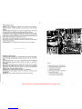
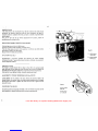
INSt
Alli\~IONE
Tostd
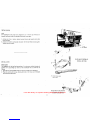
Per l'instUIIilzione
dcHn
testa ed
ii
collegi.inmnto con il motore (gici montatc
sui
hancale}. mediante cinghia
di
trasmfssione, procedere come segue:
L prernere con forza i quattro tamponi ammortizzatori
sugli
appositi perni della
pi<~stra
sostegno
2.
piazzare
Ia
macchimi
sUI
bancale centr<lndo i
fori
infer!ori de!la testa
sui
qu~ttro
lampani l.lmmortizzatorl. '
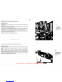
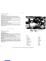
INSTALLATION
Head machine
the
lnslallation of the head and connection
of
it
to the motor !which
is
already
in
position
.on
its rpountings) by means of the transmission belt
is
carried oui
as
follows:
t.
Force the four' spring-loaded bushes
intO
the pins attached
to
the base-plate.
2.
Place
the machine
rih
the
bilse,
locating the holes
in
the lower part of the
head
on the spring-loaded hushos.
1
··,
'·
1,
A-
perno
sostegno testa
pin
for
head
PIAZZAMENTO INCASSATO
SUBMERGED SETTING
... J
..
·
..
·.·
TO
Y..Run.
PIAZZAMENTO NORMALE
NORMAL SETTING
I
~7
\.
1
...
···
....
~
From the library of: Superior Sewing Machine & Supply LLC

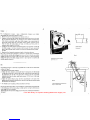
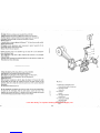
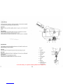
Cirigitla
.' , .
Per·
ii coflcgamcnto motore . testa e
indispens<Jbile
impiegure UrHl cinghia
trapcioidale dalle dimensioni indicate
in
rigUrti
1.
1. Montarc
Ia
cinghitt
di
trasmissione come
illustr<Jto
in
fig.
2.
2.
Registrare
Ia
tensiOne della cinghia agenda sullo snodo attacco motore,
in
modo
da non consentire slittamenti,
rna
avendo cura di non tenderla eccessivamente
onde evitare sovraccarichi sugli alberi delle pulegge e non compromettere
Ia
durata della cinghia stessa.
Si
ha
Ia
glusta tensione quando, premendo con
Ia
mana
al
centro
del
tratto Iibera
piU
lunge,
si
verifica
una
freccia,
cioEt
un
cedimento della cinghia, di 10·15 mm.
3.
Livcllare
Ia
testa della macchina affinchi!
Ia
cinghia
si
trovi
sui
piano normale
agli
assi
delle pulegge e
cioi!
lavori
al
centro delle lora
~ole.
Per
questa operazione
ngire
sui perni sostegno testa, avendo
cur
a di bloccare successivamente
gli
appo.
siti dadi.
4.
Monlare fnfine il coperchio protetione dnghia,
in
dotnzione
alia
testa.
N.B.
:
Perf
primi 20 giorni impiegare
Ia
macchina a velocitil ridotta, montarido
Ia
cinghia nella gala piccola della puleggia del motore,
al
fine
di
ottenere un perfetto
rodaggio che assicurercl
Una
piU
lunga durata della macchina.
In
seguito spostare
Ia
clnghia nella gala grande della puleggia motore e quindi portarc
Ia
rnacchina
alia
vt:focit8
maSsima
conscn
til
a.
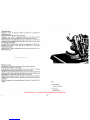
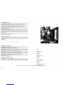
Bell
To
cOnnect the
motor
to the
head
a trapezoidal belt must
be
used with dimensions
us
shown
in
Figure '1.
1.
Fit the belt
as
illustrated
in
Figure 2.
2.
Adjust the belt's tension
by
turning the motor's fixing-screws; the belt should
not be able to slip, but
it
must not
be
too tight, otherwise
the
pulley-shafts
will
be overloaded
und
tl1e
life of the uelt
will
ue
reduced.
The
belt
is
correctly
adjusted when there
is
a play. under hand pressure, of 10·15
mm.
in
the longer
section of the
belt.
3. Adjust the machine tlead
so
ttlat the belt
is
perpendicular to the axes of the
pulleys and thus centred
In
th~ir
grooves.
This
is
done
by
adjusting the pins which
fix
the head to the base-plate.
4
Fix
the belt cover
in
positiofl, which
is
attached to
the
head.
N.B.
For the first twenty days, run the machine at a reduced speed, placing the belt
in
the
small
groove
of
the motor pulley
to
obtain perfect running·in which ensure a
much longer
life
for the machine.
Afterwards place the belt
In
the
large
groove of the pulley and bring the machine to
lull speed.
coperchio
protezione
cinghia
9~lilld
IJUIJ
C~IVlH
Fig.
2
s.chema collegamento motor&- testa
engine·
machine
head
10
iezione
clnghia
belt
section
Fig.
1
I
"'
7
From the library of: Superior Sewing Machine & Supply LLC

..
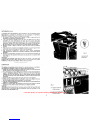
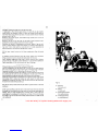
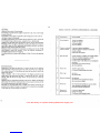
RIF(JRf.JtrvuiNro
ouo
La
niacchina esce dagli stabilimenti senza lubrificante, per cui e necessaria prima
deii'Svviamento, prowedere
al
rifornimento
di
olio, impiegando
il
lubrificante
VR604 (Esso Standard Teressa 43),
ed
operando come segue:
1.
Far ruotare
il
piano
di
Iavere verso l'esterno e svitare
il
tappa
del
foro
di
rifornlmento sui coperchio cinematismi
(fig.
3).
2.
Per il rifur.,imento complete versare
nel
foro circa 600 gramrni
di
olio e
controllare
che
!'ago.
dell'indicatore
di live\lo (fig. 4·AI.
pasta
sulla
parte
anteriore della testa. raggiunga
Ia
posizione
MAX
(fig.
4); tenendo presente che il
movimento
dell'ago
ha
un
certo
ritardo
rispetto
all'aurnento di livel\o dell'olio
(si muove
dopa
che
sana
stati
versati circa i
2/3
della capacita della bacinella).
3. Riavvitare quindi
il
tappa e riportare il piano di lavoro nella
sua
posizione
normale.
4. Prima
di
avviare
Ia
macchina e consigliabile lubrificare con qualche goccia d'olio
Ia
barra
del
morsetto porta ago e
gli
snodi
del
crochet superiore.
5.
Fare funzienare
Ia
macchina a vuoto per circa 5 minuti, aumentando
progressivamente
Ia
velocit3 fino a portarla
da
1500
giri
al
minute
alia
velocit8
d'implego.
6.
Ourante il funzior1amente controllare
II
circuito di lubrificazione attraverso
Ia
spia trasparente del coperchio distribuzione olio, situate sotto il coperchio delle
tensioni
fig.
4.
lmportante:
La lancetta dell'indicatore live/to
Olio
non
deve
rnai
superare i due tratti
rossi
all'csterno dei pUnti
MIN
e
MAX,
perch~
net prime caso
Ia
lubririctrzione sarebbc
lni!ffi.clente, nel secondo
sl
Potrebbero veHficare fuoruscite
di
olio.
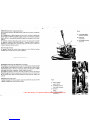
LUBRICATION
The machine
is
despached without oil and it
is
therefore necessary to
oil
before.
Use
VR604 (EssoStandard Teresso 43),1ollowing the procedure below:
1.
Rotate the work·table towards the outside and unscrew the filler plug of the
oil· hole, which
is
on
the mechanism's cover (Fig. 3).
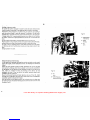
:i.
For a
full
supply pour about 600 grams of
oil
into the hole and check that the
needle of the oil·leve) Indicator (Fig, 4·A), which
is
on the front of the head,
Indicates
MAX
(Fig.
41.
Note that there
is
a delay between increase of the
level
of
oil
and movement
of
the needle
Ot
begins to
move
the reservoir
is
about two
thirds full),
:l.
Replace ihe filler plug and replace the work·table
in
its normal position.
4.
Before starting up the machine
it
is
advisable to apply a few drops
of
oil
to
the
bar of the needle·holder and the bearings of the upper looper.
5, Rutl the machine uhloaded for about 5 minutes, gradually increasing speed from
1500 r.p.m. to operating speed.
6.
While
It
is
running, check the lubrication circuit through the window
In
the all
distribution cover, which
is
under the tension·cover.(Fig.4) Important
lmpbrtant .
The ·needle of the oil·level Indicator must never
go
beyond the red lines which mark
MIN
and
MAX:
in
the Iarmer case the lubrication would be insufficient,
In
the
latter there could be leakages of all.
I/
Fig.
4
A - lndica1ore \lvello alia
oil
level
indicator
all circuit window
Fig.
3
taPpa car lea alia
oil
filler
plug
From the library of: Superior Sewing Machine & Supply LLC

MONTAGG'IO
E FASATURA ORGANI
Dl
CUCITURA
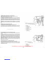
Posizionamento
ago
L'CJQo
e
lnfilato
a
battuta
noll'
apposite
foro
del
morsetto
ed
e
b!occato
dalla vile ad
csagono interne.
Sl
ha
Ia
corretta posizione dell' ago quando
Ia
punta della stesso
si
trova
at
centro
della feritoia esistente sulla placca d'ago.
Con
ago
a!
punta
marta
superiore,
Ia
distanza
"a"
fru
ago
e piano della placca
lfig.5J deve risultare quell a indicata
sui
foglio
di
fasatura che correda
Ia
testa.
Nel_
case che
ciO
non
si
verificasse, effeltuare
Ia
corre~ione
allentando
Ia
vite
del
hraccio
eli
manovclla
{fiQ.61
alzare
Od
al.Jbassare
il
morsetto
ago,
tenendo
fermo
i1
volant
ina
manta
to
suil' albero principal e.
Escguita
ia
corrczione, stringere nuovamente
Ia
vite.
FITTING
AND
ADjUstiNG
OF
tHE
SEWING
MECHANISM
Positioning the needle
The needle
Is
lnS~>rted
into the hole of the clamp and
is
fixed
by
a hexagonal screw.
The needle
is
positioned correctly
w~en
its point
is
In
the center of the necdle·plate
hole. •
When the needle
is
in its
top
position, the distance 1
'a"
between needle and piate
(Fig.
51
should be
as
shown
in
the Talbe
of
Adjustment, which
is
attached to the
head. To adjust this distance, unscrew the screw on the arm of the crank
(Fig.
6)
and
raise
or !ewer the needle·holdet without moving the knob mounted on the main
shaft. After the adjustment, tighten the screw.
10
t'l
•
Fig.
5
a-
distanu
ha
ago
e
piano placca
distance
between
needle and needle
plate
Fig.
6
vha fluagglo manovella
comando barr1
ago
screw
for
needle bar
control lever
From the library of: Superior Sewing Machine & Supply LLC

. . .
So.H1tuzlorie
'dell'
ago
Spegnere
II.
motore
ed
asslcuratsl,
mediante
il
pedale,
che
Ia
macchina
sia
asso(utamehte ierma.
Portare
manualmente
I'
ago
at
pun
tO
tnortQ
supe'riore.
Abbassare
Ia
leva
A iflg.
7)
e
splhgendola
leggermente
verso
destra,
bloccarla
sull'apposlto iermo;
far
tllotare il pledino
verso
Illata sinistro
della
macchina.
Alientari!
Ia
vite
serra
ago
I!
(fig.1L
estrarre
I'
ago
e sostltuirlo
con
il nuevo.
Tenere
presente
che
i'inc~vo
passaggio
Crochet
deve
essere
rivolto
verso
il
salva
ago
e
cio9
verso
l'lnterno
deila
macchina.
Servendosl
della
pinza
irl
dotazion¢, accetlarsl
che
!'ago
~ppoggi
sui
fonda
del
foro.
Strlngere
senza
eccedere
Ia
vile
serrd
ago
B,
avddo
cura
di
non
varlare
1
1
oiientamehio dell'
ago,
Rlportare quindl il pledind
nella
posiziohe
normale
di
lavoro
ed
alzare
Ia
leva
A,
liberandola
dal
Ierma,
Replacing
the
needle
Stop the motor
and
ensure that the
machine
is
off
by
operating
the
pedal.
By
hahd,
raise
the needle to
Its
top position.
lower the
lever
A lFig.
71.
press
It
slightly
to
the
right
and
lock
it
on
the
stop
Provided;
rotate the presser-foot
toWards
ihe left side of the machine.
UnscreW
the
screw
B
Which
holds
the needle,
remove
the
needle
and
replace
It
with
the
new
one.
The
notch
which
allbw.;
the
shuttle
to
pass
must
be
turned towards
the
needle·guard,
In
other
Words
towards the
Inside
of
the
machine.
Using
th~
pincers provided, check that
the
needle
Is
pushed
to
the
end
of
the
hole.
tighten, without lorcing, the
screw
B,
taking
care not to
change
the
orientation
of
the
needle.
lie turn the p•esser·foot to
Its
normal
posltloh
and
lilt the
lever
A,
removing
it
from
the
stop.
\2~
Fig.
7
A-
leva alza piedino
presserroot lifting lever
B -
vhe
serra
ago
needle fixing screw
From the library of: Superior Sewing Machine & Supply LLC

~oililonam~nto
piedino e regolazione presslone
Sl
ha
Ia
corretta posizione
del
piedlno quando
I'
ago
passa
fra
Ia
slilla e
Ia
linguetta
del
piedino,
Per
I~
regolazlone e sufficiente alleritare
Ia
vite A
(fig.
Bl,
che blocca
il
piedino
alia
leva.
In
queste condizloni e possiblle spostare assiatmente o radlalmente
II
piedino
rlspetto
alia
le·IP,
a seconda delie
necessd
di
regolazione. Stringere quindi a Iondo
Ia
vito
A.
Per
regal
are
Ia
pressione del piedino;
ilgehdo
attraversa
I
fori
appositamente prevlsti
sui
coperchio superidre
della
teSM,
allerltare
. mediante l'apposita
chia~e
In
dotatlone ·
Ia
vite B (fig,
~I
e con
un
cacciilvhe
agire
sulla
vlte C (fig. 8).
Otten~ta
Ia
prcssione
desiderata
blot:care
Ia
vite 8.
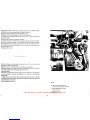
Fasatura
crochet inferiore
Per
regol8re
l'altezza
del
crochet
ihreriore
allentare
Ia
vite 8 (fig.9)
ed
uvvitare
<UII'
albero porta crochet
in
ieriore
il
calibre 5.1555.00.
PoSitioning the
pressedoot
and adjustment of
its
pressure
The
presser-foot
is
positioned correctly when the needle
passes
between
the
siide
and the tongue
of
the presser-foot
To
adjust it, unscrew the screw A
(fig.
81
which
locks the' presser-loot to the lever.
The
foot
can
then
be
moved
axially or radially
with respect to
th~
lever,
as
necessary. Finally retighten the screw A.
The
adJust the pressure of the foot,
use
the
key
provided
to
unscrew the screw B
(Fig.
81
through the holes
in
the upper cover of
the
head,
and
turn
the
screw C
(Fig.
SJ
with
a Screw·driver.
When
the
re~uired
pressure
has
been obtained, retighten
the
screw
il.
AdJuitment
rif
the lower looper
To
adjusi the height of the lower looper,
loo1en
the screw B I
Fig.
91,
and
screw the
calibratc>r
S,
1555.00 on
to
the shalt of the looper.
14
il
Fig.
9
A-
calibro S 1555.00
gauge S 1555.00
B-
vlte fluagglo crochet lnf.
lower
looper
fixing
screw
C -
squadretta
bracket
b -
vlte
fls.saggio
squadretta
bracket
screw
fig. 8
A - vltt
bloccagglo
pledlno
presserfoo1
fixing
screw
~
-
vlte
dl
hrmo
retaining
screw
C - vlte regolulone prnslonfi
presser
$Crew
From the library of: Superior Sewing Machine & Supply LLC

POslc"lonare:i~·crochet
in
modo che
hi
sua
punta coincida con una
derle
due tacche
del
calibro, lsecondo quanto specificate
sulla
tabella
di
fasatura).
Bloc~are
quindi,
sen:za
forzare,
il
crochet mediante
Ia
vite
B.
Regolare
Ia
posizione
della
squadretta
C,
(fig.
91
allentando
Ia
vite
La
squadretta c deve essere fissata quando e a contatto con H piano terminale
del
gambo
del
croc~et.
Smontarc quindi if
en
libra
in
preceden:za impiegato,
La
regolare posizione
del
crochet inferior'e rispetto all'ago
si
ha
quando con crochet
spostato
tutto
a
sinistra
Ia
Qllota
"b"
risulta quell a indicata sulla tabella di fasatura.
Per questa regolazione e necessaria allentar'e
Ia
vite E (fig, 1
0)
e
spostare
Ia
leva F
(Hg. 10) intorno
al
sud asse·
di
rotciiione, fino
ad
ottenere
Ia
corretta distan:za fra
ugo
~
punta del crochet.
Stringere
quindi
ia
vite
E.
J
PoSition ttie looper
so.
that
hs
point coincides with
one
of the two notches of the
gauge
(see
the Table of Adjustments!.
Retighten,
without
forcing,
the
screw B to lock the
looper
in
position.
Check
the
positio.n
ol the plate C
(Fig.
91
by
loosening
the
screw
B.
The
plate C
must
be
fl.xed
when
I(
Is
in
contact with
the
looper flat
end.
Remove
the
gauge'.
The
looper
Is
posiiioned correctly with respect to
the
needle
when,
with the looper
as
far
as
possible to the left,
the
distance
"b"
is
as
shown
in
the
Table
oi
Adjustments.
To
ad)usi
this, the screw E
(Fig.
idl
should
be
loosened
and
the
lever
F I
Fig.
10)
moved
around
Its
axiS
ol
relation,
Until
the
correct distance
between
the
needle
and
point ollhe looper
Is
obtained.:
Finally,
rliiig~ten
the
screw
E.
16
Fig.
10
b-
dlstanza
fra
crochet
lnferlara
e
ago
dhtance between lower looper and
needl11
E
-vita
bloccagglo levi porta crochet
looper
fixing screw
F - leva
porta
crochet
looper
lever
From the library of: Superior Sewing Machine & Supply LLC

rauituta cfochet supcriore
A!lentare
I~
viti
A e a
(llg.
11).
tontrollare l'incrocio
del
crochets e
regolare
in
modo
che ruotando
il
trochet supetiore,
Ia
sua
punta
sfiori
il
dorso
di
quello
lnferlore.
Controllare quindi che
Ia
distanza "e"
fra
!'ago
e
Ia
punta
del
crochet,
in
posizione
di
fine
corsa
sinistra
corrlsponda a
quell
a
indicata
sulla
tabella
di
fasatura.
Controllare che
il
crochet.
sUpE!riore
spostandosi
da
sinistra
verso
destra
sfiori
I'
ago,
In
caso
contra
rio
allentare
leggermente
Ia
vite
C
(fig,
11)
che
blocca
Ia
bussola
della
gulda
osclllante
.e
spostare
verso
l'ihterno
o l'esterno
della
macchina
il
gruppo
porta
crochet
senza
variare
Ia
quota precedentemente ottenuta.
Bloccare
Ia
vite C
.e
verificare
ulteriorment~
il
sincronismo
del
movimento.
Dopa questa operazione e oppoi"luno controilare nuovamente l'incrocio
dei
due
crochets e
Ia
quota
suddetta.
Stringere
quindi
le
viti
A e
i3
ed
asslcurarsl
che
i
gruppi
si
muovano
1iberamente.
Adjustmenl
of
the
upper looper
Loosen
the
screws
A
and
B
(Fig.
111.
Check
the alignment
of
the loopers
and
adjust
them
so
jhat
when
the
Upper
looper rotates
Its
point
grazes
the
back
of
the
lower
looper. '
Check
that the distance
"c"
(or
''e" for e blind looper) between the needle
and
point
of
ihe looper,
when
this
Is
fully
lo the left,
Is
as
shown
in
the
Table
of
Adjustments,
Check
that the upper looper
grazes
the
needle
when it
moves
from
left
to
right;
11
this
Is
not the
case,
slightly
loosen
the
screw
C
(Fig.
111
which
locks
the oscillating
gulde·sleeve
and
move
the Jooper·carrier towards
or
away
from
the
inside oi the
machine, without alterning the distlnce already set.
Tighleri
the
screw
C and
check
the synchronisation
ol
the movement.
Alter
this
op•rotlon It
Is
advisable
to
re·check
the alignment
of
the
loopers
end
the
above
distance.
lietlghteil the
screws
A
and
il
and
check
that the mechanism
moves
freely.
IB
IZ
Fig.
11
e - dlstanza
fra
ago
e pun to t.el crochet supflriore
distance between needle
and
upper looper end
A-
vhe bloccaggio crochet super lore
fixing screw
for
looper holder
S-vita
blocc'agglo
leva
comando crochet supetlore
looper control lever screw
C-
vite bloccagglo
buss.ola
guida
osclllante
bush fixing screw !for oscillating guide)
From the library of: Superior Sewing Machine & Supply LLC

.·.
MoniDU!JiO
e fasaiuru crochet punici catenella
(Ciasse
329·330)
fnfll~rela
bussolina di Ierma E
sui
uambo
del
crochet pun
to
catenella D
lntrodurre questa
nel
porta crochet e bloccarlo leggermente con
it
grano
A.
Conti'ollare
l'inclinazionB
del
crochet
come
da
tabella
di
fa:satura.
Bloccare
II
grana A
A crochet tutto a sinlstra, registrars
Ia
distanza
"a"
fra
l'ago e
Ia
punta
del
crochet,
agenda su\l'eccentrico
B.
Nell'esegllire questa operazione
avere
i'avvertenza
di
feriere
i'ccc.entrico
B
con
et.centricitB
massima
rivolta
verso
il
basso.
Bloccare
l'eccentrico coh
il
grana
C.
Montare
Ia
placca d'ago e
fare
scimdere
!'ago
in
modo che
Ia
punta
oltrepassi
il
piapo della piacca d'ago.
Tirare
leggermente
t'ago
verso
ia
parte
anteriore
della
macchinu
e
far
proseguire
all'
ago
Ia
discesa.
In
questa modo coritrollare che
Ia
pUnta
dell'
ago
non
passi
davahti
al
crochet,
rna
fietta sempre
sui
dorsa della stesso.
fitting
and
adjusting of
tho
chain-slitch looper
(Class
329-330)
Place
ihe
bush E on the stem of the chain-stitch looper
D.
Piace
the. Iotter
ori
the looper-carrier and
fix
it
lightly with the screw
A.
c;heck
the lnclinat)on
ol
the looper(see Table of Adjustements).
Tighten the screw'
A.
With
the looper completely to the left, adjust the distance
"a"
between the needle
and the point of the looper
by
turning
the
eccentric
B.
While
carrying out this
operation, take
care
to keep
the
maximum eccentricity of
the
eccentric B pointed
downwards.
Fix
the eccentric with the screw
C.
PUt
the, needle-plate
In
position and lower the needle until the point passes below
the plane of the needle-plate. Puli the needle lightly towards the front of the
machine, and continue to lower It,
In
this way, check that the needle does not
pass
In
front of the looper, but still bends
on
the back of the looper.
20
Fig.
11
bis
a-
distanza
fra
ago
e punta
del
crochet
distance between needle
and
looper
end
A - vlte flssagglo crochet
looper screw
B-
uccentricO
eccentric
C-
vita
flssaggio eccentrlco
eccentric screw
0 - crochet punto catenella
charn
stitch looper
E -
bu55ola
di
fermo
bU5h
a
From the library of: Superior Sewing Machine & Supply LLC

M~ntagg\o
e
r~golazione
spinSi
asola
e
salva
ago
(Ciasse
327)
La
s~ingi
asola
A
(fig,
121
deve
essere
montato
in
modo che, con
ago
al
punta
rf!OTto
lnferiore,
sia
accostato a questa e
Ia
punta
del
crochet inferiore nella
sua
Corsa
verso destra
venga
a sfiorare !'ago stesso.
In
questa posizione bloccare
Ia
spingl
asola'con
Ia
vita C (fig.' 12).
Montare
il
salva
ago
'B
lfig,12), avvicinandolo all'ago quando questa
si
trova
al
punta marta lnferiore.
Bloccare
i1
salva
ago
con
Ia
vite D
(fig,
i2),
alia
quale
si
accede attraverso il foro
apposltamente
previsto,
sulla
parte
anteriore
del
carter
laterale.
Controllare che durante il funzionamento, per eventuali flessioni, !'ago non
uni
contra
U
crochet
!nferiore e possa quir1dl rompersi,
La
verllica
si
esegue
flettendo
!'ago
verso
!'interne della macchina e controllando
che
il crochet, spostandosi
da
sinistra verso destru,
e11tri
nell'incavo dell'ago senza romperlo.
N.B.:Per rbssuti
sintetici
molto
duri
far flettere maggiormente /'ago su/lo spingi
asola.
In
condizioni norrnali,
QuandO
Ia
punta
del
crochet inferiore entra neU'incavo
dell'
ago,
questa deve essere a contatto della spingi asola e
del
sa
Iva
ago.
\noltre, spingendo leggermente !'ago infilato e portato
al
punta morto inferiore.
contrail
Salva
ago,
il fila
deve
scorrere liberamente.
In
caso cbntrario significa che
I'
ago
I!
troppo basso
edit
fila viene Hattenuto
Ira
!'ago e il
salv.B
ago.
22
filling and adjustinS ol Irani and'rear needle-guard
(Class
327)
The
front needle-guard must
be
fixed
so
that it
is
close to the needle when the
latter
Is
at lts lowest point of travel, and the point
of
the lower looper
at
the same
time
grazes the nlcdle.
Fix
It
in
this position with the screw C (Fig. 12).
FIX
the rear
neecHe-gUard
B I Fig. 12L bringing it up to the needle when the latter
is
at
Its
lowest point of travel.
'Fix
the
rear
needle·guard with the screw 0 (Fig, 12)
which
Is
accessible through the hole bored
in
the front part of the
side
cover.
Check
that during operation the needle does
no1
hit against the lower looper and
so
risk
breaking. This
Is
checked
by
bending the needle towards the inside
of
the
inach1ne
and verifying thai the looper,
when
moving
from
left to right, enters into
the notch of the needle without breaking h.
N.
B.
With very hard synthetic cloth bend the needle
ro
a greater
extent
on the front
needle-guar.
Under
normai
conditionS,
when the point of the lower looper enters the notch of
the needle, the lanet should be
in
contact with the front and rear needle-guard.
In
addition, with the needle threaded and at its lowest point of travel, when It
is
pushed against the needle-guard the thread must run freely;
if
this
is
hot the case,
\he needle
is
too low and the thread
Is
being )rapped between the needle and the
rear
needle-guard.
Fig.
12
A - splngl
B50la
front
needle guard
8-
salva
ago
rear needle guard
C-
vlte bloccagglo splngl asola
front
needle
guard
screw
0
-vito
bloccagglo
Plve
ago
rear
needle
guard
screw
From the library of: Superior Sewing Machine & Supply LLC

Montaggio
e
regola~ione
spingl
asola
e
salva
ago
(Ciasse
3291
Mantare
sulio
splngf
asofa
b
If
salva
ago
A stringendo
leggcrmente
Ia
vite
B.
Flssaie
con
le
viti C
lo
splngl
asola
D
al
basamento
Con
ago
al
punta
marta lnfedore,
accostare
Ia
spingi
asola
in
modo
che
Ia
punta
del
crochet lnferfore,
nella
sua
corsa vetso destra,
sfiori
!'ago.
Bloccare
quindi
le
viti
C.
Con
tigd
ai
pUn
to
modo
lnferlore.
Svvicinare
il
salva
ago
A
all'
ago
e
serrare
Ia
vite B
lnfltare i'ago e portandolo
tunc
In
basso,
spingerla
leggermente centro
11
salva
ago
A.
Verlffcare
the
In
quesU!
condizionl
II
fila
scorra
liber~mente.
In
case con)rario
slgnlflca
che I'
ago
e iroppo
basso
ed
illilo
resta
imprigionato
Ira
i'ago
ed
il'salva
ago,
Montaggld
o regoiaziona
splngl
asola
(Ciasse
330)
Fissare
al
poria coltelfo lhferiore
lo
splngi
asola
A,
mediante
Ia
vite
B.
Con
ago
al
punta moria inferiore,accostare
Ia
spingi
asola
all'
ago
in
modo
che
Ia
punta
del
crochet,
nella
sua
corsa
verso
destra, sfiorll'ago.
Bloccare
quindi
Ia
vile
B.
Fliting
and
adjusting
ollront
and teat needle·guard
(Class
3291
Fix
the
rear
needlc·guard A
on
to
the
foont
needle
guard 0
and
lightly tighten
the
screw
B:
Fix
the
iront needle guard 0
to
the
head
base
with the
screws
C.
With
the
needle
at
ItS
lowest point bf travel.
move
the
front
needle
guard
so
that
the
Point
of
the
lower
looper,
as
It
moves
towards
the
right,
grazes
the needle. Tighten the
screws
C.
With
the needle
at
its lowest point of
travel,
bring
the
rear
needle·guard
close
to
the
needle
and
tighten the
screw
B.
Thread the needle
and
lower it, pushing it
lightly
against
lhe
tear needle·guard
A.
Check
thai under
these
conditions the thread
runs
lreely;
II
not, the needle
Is
too
tow
and the thread
is
being
trapped between the
needle
and the rear needle·guar?.
fitting
and
adjusting ol the front haedle·guard
(Class
330)
Fix
the
front needle guard A to the lower knife holder with the
screw
B.
With
the
needle
at
Its
lowest point
of
travel,
push
the
front needle·guard towards
the
needle
so
that the point ol the looper,
as
it
moves
towards the right,
grazes
the
needle.
Tighten the screw
B.
24
fig.
12 bis · splngi
asola
e
salva
ago
(
329
)
fron1
and
rear
needle
guard
{ 329 1
A-
salva
ago
fron1
needle
guard
B-
vile
salva
ago
front needle
guard
screw
C-
viti $plngi asola
rear
needle
guard
screws
D -
spingi
asola
rear ne!!dl'e guard
Fig.
12 ter ·
Spln•l
asola I 330 I
rront
needle
guard
(
3JO·
I
A - splngl asola
rear
needre
guard
B-
vlte splngl
asola
rear
needle
guard
screw
A
0
From the library of: Superior Sewing Machine & Supply LLC

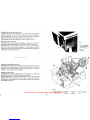
Montaggio
e rcgo\azionc co\tclli
Coltbl\o
lnferiore
(fig.
131
Per
il
montaggio e
lil
regolazione
del
toltello
lf1feriore
ope
rare
come segue:
Posizionare
sui
porta
colteilo,
senza
bloccare,
·Ia
squadretta
A
mediante
Ia
vite
8.
lnserire
il
colte!lo C
nella
sua
sede,
avendo
cura
che
il
tagliente
col
tell
a non
sporga
da\
piano
deila
ptacca, stringere qulndi
Ia
vite
D.
Con
ago
al
punta marta inferiore,
avvicinate
Ia
squadretta
E
a\
salva
ago
e
bloccare
Ia
bussola H e
Ia
ronde\ia G con
Ia
Vitc
F,
Asslcurarsl
~he
il
porta
coltello
scorra
liberatnente,
regolandolo
quindi
secondo
Ia
larghezza
di
costa
desiderata,
Stringere
leggermente
Ia
vile L
Con
ago
at
punta
morto
inferiote
avviclnare
Ia
squadretta
A
alia
spingi
asola,
bloccandola
in
questa
posizione con
Ia
vite
B.
Posizlonare
il-coltcllo
superiore
a contatto ton l'inferiore
ed
allentare
Ia
vite L
in
modo
che
Ia
molla
M
ed
il
puntaHno
N
creirio
Ia
corretta pressione
fra
i
due
coltelli.
Stringere quindi
Ia
vile
L.
filling
and
adjusting
of
the
knive!
lower knife
IFill:
13)
Follow
the
proce.dure
hereunder:
WithoUt
tigh,tening
It,
Use
the
screw
8 to attach the connecting·plate A to the
knile·holdsr. Insert the knlle C
in
Its
holder, making
sure
that the blade
does
not
project beyond the plane
of
the plate. Tighten the screw
B.
With
the needle
at
Its
lowest
point ol travel, bring the plate E
up
to the rear
neecUe·guardand
fix
the
sleeve
Hand the washer G with the
screw
F.
Check
that· the knlfe·holder
runs
freely,
and adjust it according to the width
of
bight required.
Lightly
tighten the screw
l.
With
the
needle
at
its lowest point
of
travel,
bring
the
plate A
up
to the lront needle·guard, and
fix
it
in
this position with the
screw
B.
Position the upper knife
In
contact with the lower knife
and
loosen the
screw
so
that the
spring
M
and
the
pin
N create the correct pressure between the two
knives.
Tighten the
screw
L.
26
fig. 13
A-
squadretta
bracket
8 - vlte per squadreUa
bracket screw
C-
co
hello
inforioro
lower knife
D - vita bloccaggio
coltello
knife fixing
screw
e-
squadretta
bracket
F
-vita
arrasto coltello
knife
grip
screw
G-
rondella
washer
H-
bU$$011
bush
I - porta
coltello
knife holder
L-
vlte
screw
M-
molla
spring
N
:-
puntallno
pin
From the library of: Superior Sewing Machine & Supply LLC

Coltello iuP.crioru (liy.
141
Per
,II
montaggio del coltello superiore A sulla placchetta
B,
Ia
quaie e vincolata
aWalbero
pOrta
cohello C
tramite
Un
perno
scorrevole,
ope
rare
come
segue:
Posizlonare il coltello nella sede rlcavata sui
Ia
placchetta B ed install are il naselle
0,
il
carterino E
(ave
manta to)
ed
il
cl'irterino
F,
bloccundo
con
Ia
vite
G.
Net
caso
fosse
Montato
II
carterino
E,
aver
cura
che
Ia
stesso
si
trovi
mol
to
Vicino
al
piano dl taglio del coltello.
Con
gruppo coltello superiore spinto tutto
in
basso,
il
tagliente deve
trovarsi
a
O,B
mrn
salta
il
tagliente
del
coltello inferiore. Ottenere questa regolazione facendo
scorrere
II
coltello superiore nella
sua
sede
obliqua e spostando
Ia
placchctta B
sui
porta
coltello
C.
Strlngere
hi
vite G
ed
assicurafsi the
il
Coltello
superiore
nella
sua
posizione
piU
bassa non tocchi
Ia
splngi
asola.
Variazione
larghezza
costa
La
costa
puo
esscre variata in larghezza
entre
limiti molto ridotti, agenda sulla
regolatione
dei
coltelll
inferiore
e
superiore.
Oltre
ceni
limiti
e necessaria sostituire
Ia
placca ago.
Fitting
the
upper
knife I Fig.
141
To
mount
the
upper
knife A
on
the
plate
B,
which
is
attached
to
the
shalt
of the
knlle·holder C
by
a sliding pivot,
ptoceed
as
follows:
Position the knlre
In
the
notch
cut
on the plate
B.
and lit the catch
D,
the cover E
(where this
is
fitted!
and
the covet F; tighten screw
G.
When the cover E
is
fitted,
make
sure
that
it
is
very
close
to
the cutting
plane
of
the
knife.
With the Upper knife unit
as
low
as
possible, the blade should be 0.6 mm. below the
blade of
the
lower knile. Adjust this distance by sliding the
upper
knife
In
its
oblique mounting and moving the plate
Bon
the knile·holder
C.
tighten
the screw G and check
that
the upper knife in its lowest position does
not
touch the front needle·guard
Variation
of
the
width
of the
cut
bight.
This
width
can
only
be varied slightly, by adjusting the position
ol
the upper and
lower knives.
To
Increase
the
variation
iri
width, the needle·plate must be replaced.
28
..31
Fig. 14
A-
coltollo superiors
upper knife
B - placchotta
plate
C - albero
porta
coltallo
knife shaft
D-
nuello
snug
E - carterlno
dl
prote:r:lone
pro~ection
sheet
F - carterlno
cover
G-
vite flssaggio gruppo coltello
knHe group screw
From the library of: Superior Sewing Machine & Supply LLC

.•
·'
M~ntagg'io
e tegolazionc griffe
Per
accedere
aile
gri
lie e necessaria
far
ruotare
il
piedino
ed
il
piano
di
lavoro verso
l'este:rno
e toglicre
Ia
placca
ago.
II
montaggio
delle
griffe
si
effettua come segue;
Poslzlonare
Ia
grilla princlpale A e
i1
grillino B
(lig.
151
sulla slitta porta grille,
Ia
quale
deve
essere
allineata
in
modo
da
consentire l'introduzione I
dul
lata
griffa
princlpale)
di
un
cacciavite
attraverso
I
due
fori
filettati
della
slitta, che servono
per
il
fissagglo
delle
griffe.
In
queste condizioni
avvitare,
non
a fonda,
Ia
vite C dallato
del
griffino, utilizzando
il
taglio appositamente praticato
sui
terminale della
vite
stessa.
Montarela
griff
a dillerenziale
D,
avvitando lcggermente
Ia
vite E
(fig.
161.
Regolare
quindi
in
altezza
le
griffe
in
modo
che
il
piano
dei
denti delle
griffe
stesse,
sporgenti
dalla
placca
d'ago,
sia
perfettamente
parallel
a
al
piano
della
placca.
Con
grirfe
nella
lora posizione
piU
alta,
J'uscita
delle stesse
dafla
placca
deve
essere
pari
all'altezza
dei
denti.
II
griffino
deve
trovarsi
piU
in
basso
rispetto
aile
a1tre
due
grille,
Strlngcre quindi
le
viti
CedE.
Fitting
and
adjusting of the feed-dogs.
To
have
access
to the feed-dogs, the pressed
oat
and the work-table must
be
rotated
towards.ihe outside, and the needle-plate removed.
The
feed-dogs
are
mounted
a$
follows:
Position the
maih
feed-dog A and the smaller feed-dog B (Fig.
151
on the slide
which
carries
the feed·dogs,
which
must
be
aligned
in
such
a
way
that a
screwdriver
can
be
lnlerted, from the
side
of the
main
feed-dog, through the two holes
in
the
slide,
Which
are
provided lor lixing the feed-dogs. Then tighten, but not
completely, the screw C
from
the
side
of the smaller feed-dog,
using
the slot
provided
on
the end of the
screw.
Mount the differential feed-dog
D,
lightly tightening the screw E
(fig.
161.
Adjust
the height ol the ieed-dogs
so
that their teeth, which project from the needle-plate,
are
perlectly parallel to the plane
of
the plate.
With
the
feed-dogs
in
theit highest position, their projection above the plate must
be
equal
to the teeth.
The
smaller leed-dog must
be
lower than the other two. Then
the
screws
C and
E.
30
ft
Fig.
16
E - vite
screw
0-
griff a differenziille
differen1ial feed
dog
Fig.
16
A - griffe
prlnclpelo
main feed dog
B - gJifflno
feed dog
C-
vita
screw
From the library of: Superior Sewing Machine & Supply LLC

·.
. . .
Regolazione rapporto trasporto
di~fcrenliale
II
rapporto
del
trasporto differenzlale
puC
essere
vari~to
dall'esterno, agenda
sui
bottdne di regolazione A
(fig.
171
situate
sui
copercliio laterale.
Per
impostare
il
trasporto differenziale,
far
scorrere
in
alto ad
in
basso
if
boltone
di
regolazione,
bloccandolo nella posizione desiderata mediante i due arresti 8
(fig.
17).
Te'riere
presente che con questa regolazione
si
ottiene
un
rappor~o
fino a 2 :
1.
Regolazlone lunghezza
del
punto
La
lunghezza del pun to puo essere variata mediante
il
v~lantino
B (lig. 1
Bl.
che a
ctuesto
scope
e
graduate
esternamente. Per
Ia
Variazione procedere come segue:
Premere It perno A e far' rllotare h volant ina B
fino
a che l'estremit<i
del
perno
stcsso
j:Jossa
inserirsi nella tacca
del
regolatore
C,
quindi ruotare con forza il
volantino B finchi!
II
numerd corrispondente
alia
lunghezza desiderata coincida con
l'indicatore
0,
rilasciare quindi
II
perno
A.
Adjustment of the differential feed ratio
The differential feed ratio can
be
varied from the outside
by
means of the button A
(Fig.
171
situated on the
Side
cover. To set the ratio, slide the
butt~n
up
or down
and lock'
It
In
t~e
required position with the
two
stops B (Fig.
171.
With
this
· orljustment o ratio.
oi
up to 2: 1 can
be
obtained.
Adjustment
ol
stitch length
31
The
length ol.stitch can be adjusted be means of the handwheel B (Fig.
181
which
is
graduated on the outside.
To
vary the length, operate
as
follows:
Press
the pushbuiton A and rotate the
wheel
B until the end
of
the pivot can
be
Inserted
In
the notch of the regulator
C;
then rotate the wheel B with Ioree until
the number which corresponds .to the required length coincides with the indicator
D.
Then release the pivot
A.
Fig.
18
Fig.
17
A-bottone:
regolazlone
trasporto dlffertnzfale
differential
knob
B-arr
uti
stoppings
A-
perno
a pulsante
B-
volantlno
C-
regolatore
0-
$ttgno
df
rlferlmanto
push
button
handwheel
regulator mark
From the library of: Superior Sewing Machine & Supply LLC

., '
Regolazioni
tensioni
li
filo
vlene
premuto
Ira
i
due
dischl
A I
fig.
19)
della
tensione, dalla molla situata
noll'interno
del
pamela,
quindi
per
avere
Ia
giusta
formazione
del
pUnta
e
necessaria
regolarc
Ia
presslone
della
molla,
avvltando
o svitando
il
pomolo B
della
tensione
stessa.
Aver
cura
In
ogni
case
di
non
ilvvllare
eccessivarnente
H pomolo,
perchC:
ciO
potrebbe causare
Ia
rottura
del
fila.
AEGOLAZIONE
CAMMA
TEND
I
FILD
!Ciasse
329-33q)
Allentar.e
leggermente
le
due
viti
della
camma
Fare
girare
il
volant
ina
della
macchina
in
sensa
di
marcia
Prima
che
I'
ago
giunga
al
punta marta superiore,
il
profile
piU
alto della camma
deve
inlziare
a
tendere
il
fila
del
crochet
Bloccare
le
due
viti
della
camma
tendifilo
AFFILATUAA
COL
TELL!
Periodicamente
e opportune
procedere
alia
affilatura
dei
coltelli
mediante
l'affilatrlce
Rimoldi
e !'apposite blocchetto (fornibile a
richiesta}
che
garantisce
il
corretto angola
di
affilatura.
Adjustment
of
tension
The
thread
Is
pressed between
the
two
discs
A
!Fig.
191
by
the spring situated
Inside
the knob; thus
to
bbtaln the correct formation
of
the stitch the pressure ol
the
spring must
be
adjusted
by
tightening
or
Unscrewing
the
tensioning·knob
B.
Take
care
not to
~ver·tlghten
the
knob,
ot
else
the
thread
could
break.
ADJUSTMENT
DF
THREAD
TENSIONING
CAM
(Class
329-330)
Loosen
slightly the two
screws
ol
the
cam.
Rotate the machine's
wheel
in
Its
normal
direction
of
rotation.
Before
the
needle reaches
Its
highest
point, the
largest
part
the
cam should start to tighten
the
thread
of
the shuttle. Tighten the
two
screws
olthe
cam.
SHARPENING
THE
KNIVES
tha
knives
should
be
sharpened periodically with the
Rimoldi
sharpener
and
the
block
(supplied on request) which
ensures
the correct sharpening
angle.
J4
Lt
Fig.
20
Camma tendlfllo
IJ29·330}
Thread take-up
cam (329·3301
Fig.
19
A-
diK:hi
tenslone
lension
discs
8 - pomolo tenslone
tension
knob
From the library of: Superior Sewing Machine & Supply LLC
La pagina si sta caricando...
La pagina si sta caricando...
La pagina si sta caricando...
La pagina si sta caricando...
-
 1
1
-
 2
2
-
 3
3
-
 4
4
-
 5
5
-
 6
6
-
 7
7
-
 8
8
-
 9
9
-
 10
10
-
 11
11
-
 12
12
-
 13
13
-
 14
14
-
 15
15
-
 16
16
-
 17
17
-
 18
18
-
 19
19
-
 20
20
-
 21
21
-
 22
22
-
 23
23
-
 24
24


in altre lingue
- English: Rimoldi 329
Documenti correlati

Altri documenti
-
Juki MO-654 Manuale del proprietario
-
Toyota SL1A serie Manuale del proprietario
-
Juki MO-734DE Manuale del proprietario
-
-
Toyota SL3487 Manuale del proprietario
-
Silvercrest SON 90 A1 Istruzioni per l'uso
-
-
ELNA 845 - Manuale utente
-
 VITO XM Manuale utente
-
MAXA OTA-VHE 60÷700 Manuale del proprietario
