

SOM
M A
RI
0
INTRODUZIONE pag. 3
INSTALLAZIONE
" 4
RIFORNIMENTO
OLIO
" 7
POSIZIONAMENTO
AGO
8
SOSTITUZIONE
DELL'AGO
"
10
POSIZIONAMENTO
PIEDINO
E
REGOLAZIONE
PREMISTQFFA
" 12
FASATURACROCHETINFERIORE
" 13
FASATURA
CROCHET
SUPERIORE
"
22
MONTAGGIO
SALVA
AGO
E
SPINGI
AGOSU
TESTE
SERIE
264
AD 1
AGO
..."
24
MONTAGGIOSALVA
AGO E SPINGI
AGOSUTESTESERIE
264
A2
AGHI
..."
25
MONTAGGIO
SALVA
AGO SU
TESTE
SERIE
261 E
263
" 27
REGOLAZIONE
SALVA
AGHI MOBILI " 28
REGOLAZIONE
SPINGI AGO "
30
MONTAGGIO
E
REGOLAZIONE
GRIFFE
(per macchine con differenziale) " 31
MONTAGGIO
E
REGOLAZIONE
GRIFFE
(per macchine con
crochet
frontal!) "
33
MONTAGGIO
E
REGOLAZIONE
DELLA
GRIFFA
(per macchine senza differenziale) "
35
REGOLAZIONE
RAPPORTO
TRASPORTO
DIFFERENZIALE
" 37
REGOLAZIONE DISPOSITIVO
DIFFERENZIALE
A MACCHINA IN MOTO .
."
37
REGOLAZIONE
LUNGHEZZA
PUNTO
"
38
REGOLAZIONE TENSIONS "
39
REGOLAZIONE
lENDIFILO
CAMMA
CROCHET
INFERIORE
"
40
REGOLAZIONE
TENDIFILO
CROCHET
SUPERIORE
"
4I
REGOLAZIONE
TENDIFILO
INTERMITTENTE AGHI . .
."
42
REGOLAZIONE COLTELLI RIFILATORI FISSI "
44
DISINNESTOCOLTELLI RIFILATORI SGANCIABILI "
44
REGOLAZIONE
RULLI
ALIMENTATORI
E
RULLI
TRASPORTATORI
POSTERIORI-INFERIORS MOTORE " 45
REGOLAZIONE
RULLI
TRASPORTATORI
POSTERIORI
-
SUPERIORE MOTORE " 47
MANUTENZIONE
"
48
•Ogni giorno ••
48
-Ogni
settimana
"
48
•Ogni 3 mesi "
50
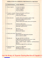
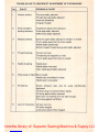
ANOMALIE
DOVUTE
A
IMPROPRIA
CONDUZIONE
DELLA
MACCHINA " 51
From the library of: Superior Sewing Machine & Supply LLC

SUMMARY
INTRODUCTION
pafle 3
INSTALLATION
" 4
LUBRICATION
" ^
POSITIONING
NEEDLE
" 8
REPLACING
NEEDLE
"
10
POSITIONING
PRESSER
FOOT
AND
ADJUSTING
ITS
PRESSURE
" 12
SETTING
LOWER
LOOPER
"
13
SETTING
UPPER
LOOPER
"
22
FITTING
FRONT
AND
REAR
NEEDLE
GUARDS
ON
264
1-NEEDLE
MACHINES
24
FITTING
FRONT
AND
REAR
NEEDLE
GUARDS
ON
264
2-NEEDLE
MACHINES
25
FITTING
REAR
NEEDLE
GUARD
ON
261
AND
263
MACHINES
"
27
ADJUSTING
MOVABLE
REAR
NEEDLE
GUARD
"
28
ADJUSTING
FRONT
NEEDLE
GUARD
"
30
FITTING
AND
ADJUSTING
FEED
DOGS
(for
machines
with
differential
feed)
" 31
FITTING
AND
ADJUSTING
FEED
DOG
(for
machines
with
front
loopers) "
33
FITTING
AND
ADJUSTING
FEED
DOG
(for
machines
without
differential
feed)
"
35
ADJUSTING
DIFFERENTIAL
FEED
RATIO
. "
37
ADJUSTING
DIFFERENTIAL
FEED
DEVICE
WITH
MACHINE
RUNNING
"
37
ADJUSTING
STITCH
LENGTH
"
38
ADJUSTING
TENSION
"
39
ADJUSTING
LOWER
LOOPER
THREAD
TAKE-UP
CAM
"
40
ADJUSTING
UPPER
LOOPER
THREAD
TAKE-UP
" 41
ADJUSTING
INTERMITTENT
NEEDLE
THREAD
TAKE-UP
"
42
ADJUSTING
FIXED
TRIMMING
KNIVES
"
44
DISCONNECTING
DISENGAGEABLE
TRIMMING
KNIVES
"
44
ADJUSTING
FEED
ROLLERS
AND
REAR
PULLERS-BOTTOM
DRIVING
...
45
ADJUSTING
REAR
PULLERS
-
TOP
DRIVING
"
47
MAINTENANCE
"
48
-
Every
day
'*
48
-
Every
week "
48
-Every 3
months
"
50
TROUBLES
DUE
TO
INCORRECT
ADJUSTMENT
OF
THE
MACHINE
"
52
From the library of: Superior Sewing Machine & Supply LLC

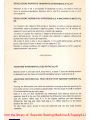
INTRODUZIOIME
Abbiamo
raccolto
nel
presente
libretto
alcune
note
relative
ali'installazione,
messa
a
punto
e
manutenzione
delie macchine Rimoldi Serie
"PIANA",
che
riteniamo
possano
esserVi
utili
per
meglio
conoscere
e
piu
convenientemente
usare
il
nostro
prodotto.
Queste
macchine
giungono
a Vo!
dopo
scrupolosi
controlli
erigorosi
collaudi
che
ci
permettono
di
garantirne
la
durata
eI'efficienza, ma Vi
ricordiamo
che
queste
dipendono
notevolmente
dall'uso
edaila
manutenzione
che
saranno
riservate alle
macchine,
pertanto
prima
dell'lmpiego,
Vi consigiianrx) nel
Vostro
interesse di
consultare
attentamente
questo
fascicolo eseguire
con
cura ie istruzioni In esso
contenute.
INTRODUCTION
This
booklet
contains
some
notes on
the
installation,
operation
and maintenance of
Rimoldi
"FLAT—BED"
machines
which
should
be useful
to
owners
and
should
help them to become familiar with
the
machine and derive the best use from it.
Before despatch, the machine was carefully checked and thoroughly tested to
ensure
its
durability
and
efficiency;
it
must,
however, be
remembered
that
these
depend very much on how the machine is operated and maintained, and It is
therefore
in
the
interest
of
the
owner
to
read
this
booklet
carefully
and
follow
the
instructions
given
in it.
From the library of: Superior Sewing Machine & Supply LLC

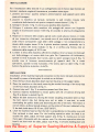
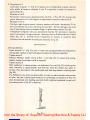
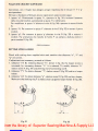
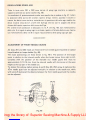
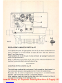
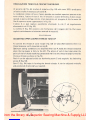
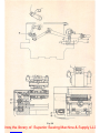
INSTALLAZiONE
Per I'installazione della testa ed il suo collegamento con ii motore
(gia
montato sul
bancale), mediante
cinghia
di trasmissione, procederecomesegue:
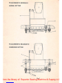
1. premere con forza i quattro tamponi ammortizzatori sugli appositi perni della
plastra di sostegno.
2. plazzare la
macchina
sul bancale,
centrando
le sedi
coniche
ricavate nelle
orecchlette della bacinella sul quattro tamponi ammortizzatori 2 {fig. 1).
3. Collegare il
tirante
1 (fig. 1} alia leva alza piedino della macchina
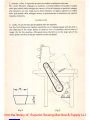
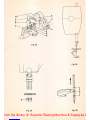
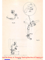
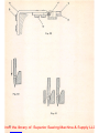
4. Collegare il volantino della macchina alia puleggia del motore con Tapposita
cinghia di trasmissione sezione 10x6 (fig. 2) secondo lo schema di collegamento
(fig.
3).
5. Registrare la tensione della cinghia agendo sullo
snodo
attacco
motore,
in modo
da
non
consentire
slittamenti,
ma
avendo
cura
di
non
tenderia
eccessivamente
onde
evitare sovraccarichi sugli alberl delle pulegge e non compromettere la
durata della cinghia stessa. Si ha la giusta tensione quando, premendo con la
mano at
centro
del
tratto
indicate in fig. 3, si verifica una freccia, cioe un
cedimento
della cinghia, di
10-15
mm.
6. Livellare la testa della macchina affinche la cinghiasi trovi sul piano normale agli
assi delle pulegge e al centro delle lore gole. Per I'operazione di livellamento,
quando la testa e piazzata fuori tavola, agire sui perni sostegno testa 3 (fig. 1),
avendo cura di bloccare successivamente gli appositi dadi. Per la stessa
operazione, quando la testa e piazzata a file tavola, agire sui dadi 4 (fig. 1) dei
bulloni
che
portano
la piastra e la
staffa.
INSTALLATION
Installation of
the
machine head and connection to
the
motor (already mounted on
the stand) by means of driving belt iscarried
out
as follows:
1. Pressthe four shock absorbers down hard on the pins on the support plate.
2. Place the machine on the stand, centering the conical housings of the sump lugs
on
the
four
shock absorbers 2 (fig. 1).
3. Connect
stay-rod
1 (fig. 1) to machine presser
foot
lifter lever.
4. Connect machine handwheel to motor pulley with 10 x 6 section driving belt
(fig. 2) as shown in sketch (fig. 3).
5. Adjust
the
belt tension by moving the motor coupling articulated joint so
that
the
belt
cannot
slip,
but
taking care
not
to make it over-taut, to avoid
overloading
the
pulley shafts and shortening the life of the belt.
The
tension is
correct when, putting manual pressureon the centre of the part indicated in
fig.
3,
the
belt yields
about
10-15 mm.
(3/8"-9/16").
6.
Level
the machine head so that the belt is perpendicular to the pulley axes and
thus centered in their races. For the levelling operation when the head is set
outside the table, adjust the head support pins 3
(fig.
1),
making
sure to lock
them again afterwards with the relative nuts. For the same operation when the
head is set
level
with the table, adjust nuts 4
(fig.
1) of bolts
holding
plateand
bracket.
4
From the library of: Superior Sewing Machine & Supply LLC


7.
montare,
infine, il
coperchio
protezione
cinghia in
dotazione
alia
testa.
Per i primi 20 giorni impiegare la macchina a velocita ridotta, montando la cinghia
nella gola piccola della puleggia del motore, al fine di ottenere un perfetto rodaggio
che assicurera una piu lunga
durata
della macchina. In seguito spostare la cinghia
nella gola grande della puleggia motore e quindi portare la macchina alia velocita
masslma
consentita.
7. Lastly, fix
on
the
belt
guard
supplied
with
the
machine.
For
the
first 20 days
the
machine should be run at reduced speed, with
the
belt in
the
small race of
the
motor
pulley, in
order
to run it in perfectly and so ensure a
longer life for
the
machine. Afterwards move the belt on to the large race of
the
motor
pulley and
then
bring
the
machine
to
the
top
speed.
10
Fig.
2Fig. 3
From the library of: Superior Sewing Machine & Supply LLC

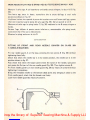
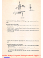
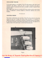
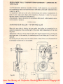
RIFORtSliMENTOOLIO
La
macchina esce dagli stabilimenti senza lubrificante, per cui e necessario prima
deM'avviamento provvedere al rifornimento olio, impiegando il lubrificante VR 604
(Esso Standard TERESSO 43) ed operando come segue:
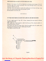
1. Svitare il
tappo
del foro di rifornimento sul coperchio (fig. 4)
LUBRICATION
The machine isdespatched without lubricant therefore, before starting to run It, oil
must be added,
using
VR 604 lubricant
(Esso
Standard
TERESSO
43),
proceeding
as
follows:
1. Unscrew
the
filler
cap
on cover (fig. 4)
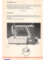
Fig. 5
From the library of: Superior Sewing Machine & Supply LLC

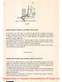
2. Versare nel foro (per il rifornimento completo) circa 750 gramml di olio e
controllare che la lancetta dell'indicatore livello (fig. 5), posto sulla parte
inferiore del montante della testa, raggiunga la posizlone MAX. Tenere presente
che il movimento della lancetta avviene dopo che sono stati versati circa i 2/3
della
capacita
della
bacinella.
Importante:
La
lancetta
dell'indicatore
livello
olio
non
deve mai
superare
i
due
tratti
rossi
all'esterno dei punti MIN e MAX, perche nel primo caso la lubrificazione sarebbe
insufficiente,
nel
secondo
si
potrebbero
verificare
fuoriuscite
di olio.
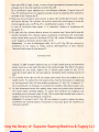
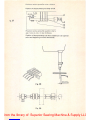
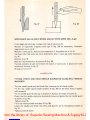
POSIZIONAMENTO
AGO
L'ago
e infilato a battura nell'apposito foro del morsetto ed e bloccato radialmente
mediante vite. Si ha la corretta posizione dello stesso quando la punta si trova al
centro
della
ferltoia
esistente
sulla piacca
d'ago
(fig. 6}.
Con barra ago tutta in alto la distanza
"a"
fra punta ago e piano della piaccadeve
risultare
quella
indicata
sulla
tabella
di
fasatura
che
correda
la
testa.
Nel caso che cio
non
si verificasse allentare la vite A (fig. 6) della fascetta B ed
effettuare la regolazlone. Serrate quindi la vite della fascetta avendo cura che la
2. For
filling
completely pour approx. 750
grams
of oil into the hole and check
that the pointer of the oil
level
indicator
(fig.
5) on the
lower
front of the
machine reaches the
MAX
position. N.B. • The pointer starts moving after the
sump
is
about
two-thirds
full,
important
The oil
level
indicator pointer must nevergo beyond the red linesoutside
MIN
and
MAX;
in the former case there would be insufficient lubrication and in the latter oil
leakages
could
occur.
POSITIONING
NEEDLE
The
needle
is
inserted
into
the
hole
of
the
clamp
and
is
fixed
by a
screw.
The
needle is
correctly
positioned
when
its
point
is in
the
center
of needle plate
hole
(fig. 6).
With
the
needle
bar
in its
topmost
position
the
distance
"a"
between
needle
point
and plate should be as indicated in
the
setting table supplied with
the
machine. If
the
distance
is
incorrect
slacken
screw A (fig. 6)
of
clamp
collar
8
and
make
the
adjustment.
Then
tighten
the
clamp collar screw, making sure
that
the
clamp
collar
From the library of: Superior Sewing Machine & Supply LLC


stessa si trovi in
battuta
verso Talto
contro
la barra ago. Regolare
I!
perno C
applicato
sulla
fascetta
in
modo
che
tocchi
il
morsetto
porta
ago.
Bloccare
a
fondo
la
vite
della
fascetta.
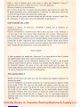
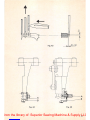
Per le teste a 2 aghi {fig. 7) a
punto
cateneila doppia e per le
teste
a 2 o 3 aghi (fig.
8)
punto
ornamento
con o senza copertura, la distanza
"a"
deve essere rilevata fra
la
punta
deH'ago di
destra
ed il
piano
della placca ago.
Per le
teste
del
tipo
punto
cateneila
doppia
ad aghi multipli a
crochet
frontali
(fig.
9),
la
distanza
"a"
puo
essere
rilevata
considerando
un
ago
qualsiasi.
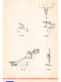
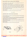
SOSTITUZIONE
DELL'AGO
Spegnere
il
motore
ed assicurarsi,
premendo
il pedale, che la macchina sia
assolutamente
ferma.
Ruotare
normalmente
il
volantino
portando
la barra ago
tutta
il
alto.
Allentare
la
vite serra ago A (fig.
10),
estrarre
I'ago e
sostituirlo
con
il nuovo.
Tenere
presente
che
I'incavo passaggio
crochet
deve essere rivolto verso
I'interno
della macchina.
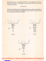
Fanno eccezione le macchine a punto cateneila doppia ad aghi multipli con crochet
frontali
per le quali I'ago dovra essere
montato
con
I'incavo rivolto verso sinistra
come
in fig. 11 e le
macchine
a
punto
cateneila
semplice
con
crochet
rotativo
per
le
quali I'incavo
dell'ago
dovra essere rivolto verso
destra
fig. 12.
is
right
up
against
the
needle
bar.
Adjust
pin
C
on
clamp
collar
so
that
it
touches
the
needle
holder
clamp.
Fully
tighten
clamp
collar
screw.
For
2-needle
double
locked
chainstitch
machines
(fig. 7)
and
2-
and
3-needle
interlock
stitch
machines
with
or
without
top
spreader
(fig.
8),
distance
"a"
must
be
measured
between
the
point
of
the
right
hand
needle
and
the
plate.
For
multi-needle
double
locked
chainstitch
machines
with
front
loopers
(fig. 9)
distance
"a"
can
be
measured
from
any
of
the
needle
points.
REPLACING
NEEDLE
Switch
off
the
motor
and
make
sure
that
the
machine
has
stopped
completely
by
pressing
the
pedal.
Turn
the
handwheel
to
bring
the
needle
bar
to
its
topmost
position.
Slacken
needle
fixing screw A (fig.
10),
take
out
the
needle
and
replace it
with
the
new
one.
Remember
that
the
notch
that
allows
the
looper
to
pass
must
be
turned
towards
the
inside
of
the
machine.
The
exceptions
are
for
multi-needle
double
locked
chainstitch
machines
with
front
loopers
on
which
the
needle
must
be
fitted
with
the
notch
turned
towards
the
left as shown in fig. 11, and single chainstitch
machines
with
rotary
hook
on
which
the
needle
notch
must
be
turned
towards
the
right
(fig.
12).
10
From the library of: Superior Sewing Machine & Supply LLC

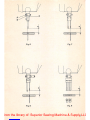
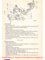
Servendosi delia pinza in dotazione, accertarsi che I'ago appoggi sul fondo foro.
Avvitare, senza eccedere nel bloccaggio, la vite serra ago, avendo cura di non varlare
rorientamento
deH'ago.
Using
the
pliers supplied
with
the
machine, check
that
the
needle is pushed right to
the
end of the hole. Tighten the needle-fixing screw,
without
forcing, taking care
not
to
change
the
orientation
of
the
needle.
Fig.
10
Fig. 11
m.
a
Fig.
12
11
From the library of: Superior Sewing Machine & Supply LLC

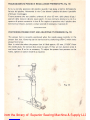
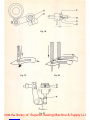
POSIZIONAMENTO PIEDINO E REGOLAZIONE PREMISTOFFA {fig. 13)
Si ha la
corretta
posizione del piedino
quando
I'ago passa al
centro
dell'apposita
feritoia
del
piedino.
Allentando
la
vite
C
che
blocca
il
piedino
alia
barra
e
possibile
effettuare
il
centraggio.
Tenere
pM-esente
che con piedino sollevato di circa 4,5 mm. dalla placca d'ago, i
piattelli
delle
tensioni
devono
essere
aperti.
In
caso
contrario
allentare
la
vite
A e
spostare
di
quanto
necessario la leva B. Per regolare la pressione
che
il piedino deve
esercitare sul
tessuto,
avvitare osvitare
secondo
il necessario, il
pomolo
D.
POSITIONING PRESSER FOOT AND ADJUSTING ITS PRESSURE {fig. 13)
The
presser
foot
is
correctly
positioned
when
the
needle passes
centrally
in
the
presser
foot
slot.
Centering
can
be
carried
out
by
slackening
screw
C
which
locks
presser
foot
to
bar.
Bear in
mind
that
when
the
presser
foot
is
lifted
approx.
4.5
mm.
(11/64")
from
the
needle
plate,
the
tension
discs
must
be
open.
If
they
are
not,
slacken screw A
and move lever B as far as necessary. To
adjust
the
presser
foot
pressure on
the
fabric,
tighten
or
slacken
knob
D as
required.
-I,''";
Fig.
13
12
From the library of: Superior Sewing Machine & Supply LLC

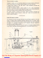
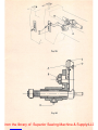
FASATURA
CROCHET
IIMFERIORE
Teste
con
crochet
laterale
Inserire
fino
a
battuta
il
crochet
A
nell'apposita
sede
del
porta
crochet
e
bloccarlo
sul
piano
di
riferimento
del
gambo
con
la vite B (fig.
14).
Controllare con
11
foglio di fase (allegato alia macchina) che le misure riportate su di
esso
corrispondano.
Nel
caso
si
dovessero
effettuare
alcune
registrazioni
operare
come
segue:
1. Per
ottenere
la
quota
'c'
fig.
15
portare
il
crochet
tutto
a
destra,
allentare
la
vite
Ldella
fascetta
M e agire sul
tirante
Ndella biella (fig. 16) sino ad
ottenere
la
quota
prescrltta
dalla
tabella
di
fase.
2. Per
ottenere
la
quota
0,05
(fig. 17) che
rappresenta
la
distanza
fra la
punta
del
crochet e I'incavo dell'ago durante la sua corsa da destra a sinistra allentare la vite
G (fig. 18) e registrare
facendo
ruotare
I'albero H.
3. Sulle
teste
ad 1 ago
punto
catenella
doppia
classe
264
la
punta
dell'ago,
durante
. la sua discesa,
deve
coincidere
con
il
punto
di
convergenza
delle 2 linee che
formano
il
profile
inferiore della lama del
crochet
(fig. 19).
Sulle
teste
a
punto
ornamento
tipo
261 e
263
la
suddetta
condlzione
si avra
con
I'ago
interne.
SETTING
LOWER
LOOPER
Heads
with
side
looper
Fit
looper
Aright
down
in its
seat
in
the
looper
holder
and
fix it in
position
with
screw B (fig.
14).
Check
that
the
measurements
correspond
to
those
in
the
setting
chart
supplied
with
the
machine.
If
adjustments
must
be
made,
proceed
as
follows:
1. To
obtain
distance
"b"
(fig. 15) bring looper fully to
the
right, slacken screw L
of sleeve collar M
and
adjust stay-rod N of
connecting
rod (fig. 16) until
the
distance
indicated
in
setting
table
is
obtained.
2.
To
obtain
distance
0.05
mm. (fig. 17)
which
represents
the
distance
between
the
point
of
the
looper
and
the
needle
notch
during
its
stroke
from
right
to
left,
slacken
screw
G (fig. 18)
and
adjust
by
turning
shaft
H.
3. On Class
264
1-needle
double
locked
chainstitch
machines
the
needle
point,
during
the
downward movement of needle,
must
coincide
with
the
point
of
convergence
of
the
2 lines
forming
the
lower
outline
of
the
looper
blade
(fig.
19).
On
261
and
263
interlock
stitch
machines
the
above
condition
is
in
relation
to
the
inside
needle.
*
13
From the library of: Superior Sewing Machine & Supply LLC

Sulle
teste
264
a 2 aghi, invece, la cruna di ogni ago
durante
la discesa deve essere
allineata con il
foro
del rispettivo crochet (fig. 20).
Se le condizloni sopra esposte non si verificassero, allentare 12 grani internt Q
(fig. 21) deU'eccentrico 0 e regolare facendo ruotare
11
votantino della macchina,
tenendo
fermo
I'eccentrico
0.
4. Nella sua
corsa
da
destra
verso
sinistra la
punta
del
crochet
deve
trovarsi a
meta
deM'incavo dell'ago. Per
ottenere
cio
occorre
accorciare od allungare la corsa del
crochet agendo sulla vite P (fig. 21) e modificando la quota 'c' (fig. 21).
In caso di variazione della
quota
'c'
enecessario rivedere la condizione del
paragrafo 1).
5. Gli aghi nella loro discesa devono entrare in
contatto
con il dorso della lama del
crochet
flettendo.
Per
ottenere
questa
condizione
enecessario
che
il prolunga-
mento ideale della tacca di riferimento D (fig. 18), incisa suH'albero principate,
risuiti tangente al diametro esterno della vite E.
Attenzione
• in caso di sbloccaggio delle viti E ed F (fig. 18), per
ottenere
le
condizioni
di cut
sopra,
la faccia
esterna
deU'eccentrico
C
deve
sfiorare
I'estremita
della
tacca
di
riferimento
D.
Instead,
on
264
2-needle
machines
the
eye
of each needle
during
the
downward
stroke
must
be in line
with
the
hole of
the
relative
looper
(fig.
20).
If
the
above
conditions
do
not
result, slacken the 2 internal
grub
screws Q (fig. 21) of
eccentric
0 and
adjust
by
turning
machine
handwheel
while
holding
eccentric
0
still.
4. In its
stroke
from
right
to
left
the
looper
point
must
be at
the
midpoint
of
the
needle
notch.
To
obtain
this,
the
looper
stroke
must
be
shortened
or
lengthened
by
turning
screw P (fig. 21)
and
modifying
distance
"c"
(fig.
21).
If
distance
"c"
has
to
be
altered
it is
necessary
to
re-check
the
condition
described
in
point
one.
5.
In
their
downward
stroke
the
needles
must
come
into
contact
with
the
back
of
the
looper
blade,
bending
slightly.
To
obtain
this
condition
an
imaginary
line
extending
from
reference
notch
D (fig. 18) on
main
shaft
would
have
to
be
at
a
tangent
to
the
external
diameter
of
screw
E.
Attention:
If screws E
and
F (fig. 18) are
undone,
in
order
to
obtain
the
above
conditions
the
external plane of eccentric C
must
just
graze
the
extremity
of
reference
notch
D.
14
From the library of: Superior Sewing Machine & Supply LLC


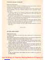
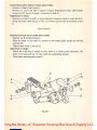
Teste
con
crochet
frontal!
1.
Fasatura.crochet
inferiore
• Inserire fine in fondo icrochet Z neM'apposita sede e bloccarli leggermente con
la vite L (fig. 23).
•Allineare I
crochet
come
in fig. 22.
-Allentare le viti K e V
che
bloccano iporta
crochet
R e la piastrina S (fig. 23)
- Portare gli aghi al punto morto inferiore, allentare le viti Y (fig. 23) e, agendo sul
supporto
dei
porta
crochet
T, eseguire la
quota
"d"
di mm
2,5
dalla
punta
dei
crochet
agli aghi (fig.
24).
Posizionare i
crochet
Z in modo che, nella loro corsa, sfiorino gli aghi (fig. 25) e
regolarii in
modo
che
avanzando,
entrino
nello scalfo degli aghi nelle
condizioni
illustrate in fig.
26.
- Per ottenere questa condizione, bisogna allentare I grani E deli'eccentrico H (fig.
23) e ruotarlo fino ad ottenere la posizione illustrata in fig. 26.
-
Bloccare
le
viti
E.
•Bloccare
quindi
i
porta
crochet
mediante
le viti K e la piastrina di
unione
mediante le vitiV . Stringere afondo te viti L serraggio crochet
i{fig.
23).
Heads
with
front
loopers
1.Setting
lower
looper
-
Fit
loopers
Zright
down
in
their
seat
and
grip
them
lightly
with
screw L (fig. 23)
- Align
loopers
as in fig.
22
•
Slacken
screws K
and
V
that
fasten
looper
holders
R
and
plate
S (fig.
23)
-Bring
the
needles
to
the
bottom
dead
point,
slacken screws V (fig.
23)
and,
moving
looper
holder
bracket
T,
set
distance
"d"
of
2.5
mm.
from
point
of
loopers
to
needles (fig. 24)
-
Position
loopers
Z so
that
they
just
graze
past
the
needles
during
their
stroke
(fig.
25) and
adjust
them
so
that
they
enter
the
groove of needles as
they
move
forward,
as
shown
In fig.
26
•
To
obtain
this
setting,
grub
screws E
of
eccentric
H (fig. 23)
must
be
slackened
and
the
eccentric
must
be
turned
until it is in
the
position
shown
in fig.
26
-
Tighten
screws
E
•
Then
lock
looper
holders
by
means
of screws K
and
coupling
plate
by
screws
V.
Fully
tighten
looper locking screws L (fig.
23).
17
From the library of: Superior Sewing Machine & Supply LLC

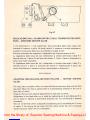
2.
Deragliatore
fill
•Controllare la
quota
"c"
(fig. 21) e qualora
non
corrispondesse aquella riportata
sulla tabella di fasatura, aiientare la vite P e registrare in modo da
ottenere
la
quota
prescritta.
•
Bloccare
la
vite
P.
-Posizionare I'astina porta deragliatore B a mm 6,8— 7 (fig. 27). Per ottenere tale
quota,
altentare
le viti A ed eseguire lo
spostamento
necessario
dell'astina
B.
-
Bloccare
le
viti
A.
Con barra ago al punto morto Inferiore, montare suM'astina ideragiiatori C (fig.
27) controllando che ialoro estremita siacirca 0,8 —0,9 mmdall'ago e che nella
fase di movimento sfiorino la placcad'ago e la griffa senza toccarle (fig. 28).
- I deragiiatori eseguono solo uno spostamento laterale. Per anticipare o ritardare
questo
movimento, bisogna aiientare i
due
grani interni Qdell'eccentrico 0 delta
biella (fig. 21) e, tenendo
ferrrvD
I'eccentrico 0, ruotare il volantino della
macchina
sino
ad
ottenere
la
condizione
illustrata
in
fig.
27.
2.Thread
deflector
- Check distance
"c"
(fig. 21) and, If It does not correspond with that indicated in
setting table, slacken screw P and adjust to obtain the distance specified.
-
Tighten
screw
P
-Position deflector holder rod 8 at 6.8 - 7 mm
(fig.
27). To obtain this setting,
slacken screws A and move rod B as required.
-
Tighten
screws
A
-
With
needle
bar in
lowest
position, set deflectors Con rod
(fig.
27),
checking
that
their extremity is approximately
0.8-0.9
mm. from the needle and, when in
motion, they just
pass
by the
needle
plate and feed dog without touching them
(fig.
28).
- The deflectors only make one lateral shift. In order to make the shift occur earlier
or later, the two internal grub
screws
Q of connecting rod eccentric 0
(fig.
21)
must be slackened and, holding eccentric 0 still, machine handwheel turned until
the
setting
shown
in fig.
27
is
obtained
0.6f07
Fig.
22
From the library of: Superior Sewing Machine & Supply LLC

La pagina sta caricando ...
La pagina sta caricando ...
La pagina sta caricando ...
La pagina sta caricando ...
La pagina sta caricando ...
La pagina sta caricando ...
La pagina sta caricando ...
La pagina sta caricando ...
La pagina sta caricando ...
La pagina sta caricando ...
La pagina sta caricando ...
La pagina sta caricando ...
La pagina sta caricando ...
La pagina sta caricando ...
La pagina sta caricando ...
La pagina sta caricando ...
La pagina sta caricando ...
La pagina sta caricando ...
La pagina sta caricando ...
La pagina sta caricando ...
La pagina sta caricando ...
La pagina sta caricando ...
La pagina sta caricando ...
La pagina sta caricando ...
La pagina sta caricando ...
La pagina sta caricando ...
La pagina sta caricando ...
La pagina sta caricando ...
La pagina sta caricando ...
La pagina sta caricando ...
La pagina sta caricando ...
La pagina sta caricando ...
La pagina sta caricando ...
-
 1
1
-
 2
2
-
 3
3
-
 4
4
-
 5
5
-
 6
6
-
 7
7
-
 8
8
-
 9
9
-
 10
10
-
 11
11
-
 12
12
-
 13
13
-
 14
14
-
 15
15
-
 16
16
-
 17
17
-
 18
18
-
 19
19
-
 20
20
-
 21
21
-
 22
22
-
 23
23
-
 24
24
-
 25
25
-
 26
26
-
 27
27
-
 28
28
-
 29
29
-
 30
30
-
 31
31
-
 32
32
-
 33
33
-
 34
34
-
 35
35
-
 36
36
-
 37
37
-
 38
38
-
 39
39
-
 40
40
-
 41
41
-
 42
42
-
 43
43
-
 44
44
-
 45
45
-
 46
46
-
 47
47
-
 48
48
-
 49
49
-
 50
50
-
 51
51
-
 52
52
-
 53
53


Rimoldi 264 Instruction Handbook Manual
- Tipo
- Instruction Handbook Manual
in altre lingue
- English: Rimoldi 264
Documenti correlati

Altri documenti
-
ELNA 845 - Manuale utente
-
Juki MO-654 Manuale del proprietario
-
Silvercrest SON 90 A1 Istruzioni per l'uso
-
Juki MO-734DE Manuale del proprietario
-
Toyota SL1A serie Manuale del proprietario
-
-
Toyota SL3487 Manuale del proprietario
-
Adler 166 Directions For Use Manual
-
LIVARNO 430596 Manuale del proprietario