FCC Compliance Statement
This equipment has been tested and found to comply with the limits for a Class B digital device, pursuant to part 15 of the FCC
Rules. These limits are designed to provide reasonable protection against harmful interference in a residential installation.
This equipment generates, uses and can radiate radio frequency energy and, if not installed and used in accordance with the
instructions, may cause harmful interference to radio communications. However, there is no guarantee that interference will not
occur in a particular installation. If this equipment does cause harmful interference to radio or television reception, which can be
determined by turning the equipment o and on, the user is encouraged to try to correct the interference by one or more of the
following measures:
• Connect the equipment into an outlet on a circuit dierent from that to which the receiver is connected.
• Consult the dealer or an experienced radio/TV technician for help
This device complies with part 15 of the FCC Rules. Operation is subject to the following two conditions:
(1) This device may not cause harmful interference, and (2) this device must accept any interference received, including
interference that may cause undesired operation. Changes or modications not expressly approved by StarTech.com could void
the user’s authority to operate the equipment.
Industry Canada Statement
This Class B digital apparatus complies with Canadian ICES-003.
Cet appareil numérique de la classe [B] est conforme à la norme NMB-003 du Canada.
CAN ICES-3 (B)/NMB-3(B)
This device complies with Industry Canada licence-exempt RSS standard(s). Operation is subject to the following two conditions:
(1) This device may not cause interference, and (2) This device must accept any interference, including interference that may
cause undesired operation of the device.
Le présent appareil est conforme aux CNR d’Industrie Canada applicables aux appareils radio exempts de licence. L’exploitation
est autorisée aux deux conditions suivantes:
(1) l’appareil ne doit pas produire de brouillage, et (2) l’utilisateur de l’appareil doit accepter tout brouillage radioélectrique subi,
même si le brouillage est susceptible d’en compromettre le fonctionnement.
Use of Trademarks, Registered Trademarks, and other Protected Names and Symbols
This manual may make reference to trademarks, registered trademarks, and other protected names and/or symbols of third-
party companies not related in any way to StarTech.com. Where they occur these references are for illustrative purposes only
and do not represent an endorsement of a product or service by StarTech.com, or an endorsement of the product(s) to which
this manual applies by the third-party company in question. StarTech.com hereby acknowledges that all trademarks, registered
trademarks, service marks, and other protected names and/or symbols contained in this manual and related documents are the
property of their respective holders.
PHILLIPS® is a registered trademark of Phillips Screw Company in the United States or other countries.
Warranty Information
This product is backed by a two-year warranty.
For further information on product warranty terms and conditions, please refer to www.startech.com/warranty.
Limitation of Liability
In no event shall the liability of StarTech.com Ltd. and StarTech.com USA LLP (or their ocers, directors, employees or agents)
for any damages (whether direct or indirect, special, punitive, incidental, consequential, or otherwise), loss of prots, loss of
business, or any pecuniary loss, arising out of or related to the use of the product exceed the actual price paid for the product.
Some states do not allow the exclusion or limitation of incidental or consequential damages. If such laws apply, the limitations
or exclusions contained in this statement may not apply to you.
Safety Measures
• If product has an exposed circuit board, do not touch the product under power.
Mesures de sécurité
• Si l’un des circuits imprimés du produit est visible, ne pas touchez le produit lorsqu’il est sous tension.
安全対策
• 製品に露出した状態の回路基盤が含まれる場合、電源が入っている状態で製品に触らないでください。
Misure di sicurezza
• Se il prodotto ha un circuito stampato visibile, non toccare il prodotto quando è acceso.
Säkerhetsåtgärder
• Rör aldrig vid enheter med oskyddade kretskort när strömmen är påslagen.
FR: fr.startech.com
DE: de.startech.com
ES: es.startech.com
NL: nl.startech.com
IT: it.startech.com
JP: jp.startech.com
StarTech.com Ltd.
45 Artisans Cres
London, Ontario
N5V 5E9
Canada
StarTech.com Ltd.
Unit B, Pinnacle 15
Gowerton Rd,
Brackmills
Northampton
NN4 7BW
United Kingdom
StarTech.com LLP
4490 South Hamilton
Road
Groveport, Ohio
43125
U.S.A.
StarTech.com Ltd
Siriusdreef 17-27
2132 WT Hoofddop
The Netherlands
1. (Optional) If mounting onto drywall, use a Stud Finder to locate the Wall Stud(s) on
your wall.
2. Hold the Hub in the desired mounting location, and mark the location of the
Mounting Holes, using a Writing Utensil (use a level to ensure the two Mounting
Holes are level).
3. Using an Electric Driver, drill Pilot Holes into each of Mounting Hole Marks.
4. Hold the Hub in the desired mounting location, aligning the Mounting Holes on
the Hub with the Pilot Holes created in Step 3.
5. Insert the Mounting Screws (x 2) through the Wall Mounting Holes and into the
Wall, and tighten the Mounting Screws until the Hub is securely fastened to the
Wall, using a Phillips Head Screwdriver.
DIN Rail Mounting
Horizontal
1. Align the Din Rail Brackets (x 2) with the DIN Rail Mounting Holes, Horizontal (x
4), located on either side of the USB Hub (rear).
2. Insert the Mounting Screws (x 4) through the DIN Rail Brackets and into the USB
Hub.
3. Using a Phillips Head Screwdriver, tighten the Mounting Screws. Be careful not to
over-tighten the Mounting Screws.
Vertical
1. Align the Din Rail Bracket (x 1) with the DIN Rail Mounting Holes, Vertical (x 2)
located on the USB Hub (rear).
2. Insert the Mounting Screws (x 2) through the DIN Rail Bracket and into the USB
Hub.
3. Using a Phillips Head Screwdriver, tighten the Mounting Screws. Be careful not to
over-tighten.
Power the Hub
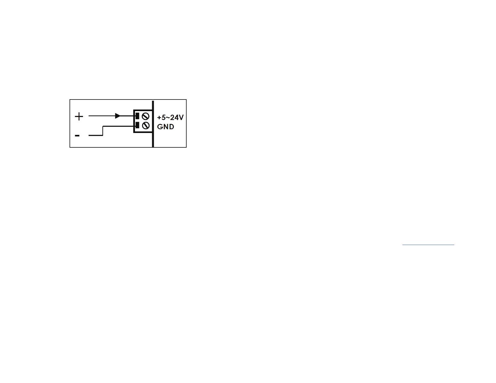
Power the Hub Using the 2-Wire Terminal Block
1. Remove the Terminal Block Connector Housing from the USB Hub’s Casing.
2. Loosen the screws for the Terminals located on the Terminal Block Connector,
using a Flat Head Screwdriver.
3. Connect the Positive and Negative Wires from the DC Power Source (+5 - 24 V DC)
to the Terminals on the Terminal Block Connector, the Terminals are marked on
the USB Hub’s Casing.
Note: Ensure the polarity of the power input is correctly matched with the DC 2-Wire
Terminal Block Pins to function properly and to prevent damage to the USB Hub and
any connected peripherals.
Terminal Block Pins
4. Insert the Terminal Block Connector Housing back into USB Hub.
Power the Hub Using an External Power Adapter
• Connect the Power Adapter to the Power Input Port, located on the front of the
USB Hub and to an AC Electrical Outlet.
Surface Mounting
Note: Always mount onto Wall Studs, when installing the USB Hub onto drywall.


