Asus Z13PE-D16 Manuale utente
- Categoria
- Schede madri
- Tipo
- Manuale utente

Motherboard
Z13PE-D16

ii
E22165
First Edition
August 2023
Copyright © 2023 ASUSTeK COMPUTER INC. All Rights Reserved.
No part of this manual, including the products and software described in it, may be reproduced, transmitted,
transcribed, stored in a retrieval system, or translated into any language in any form or by any means,
except documentation kept by the purchaser for backup purposes, without the express written permission
of ASUSTeK COMPUTER INC. (“ASUS”).
Product warranty or service will not be extended if: (1) the product is repaired, modified or altered, unless
such repair, modification of alteration is authorized in writing by ASUS; or (2) the serial number of the
product is defaced or missing.
ASUS PROVIDES THIS MANUAL “AS IS” WITHOUT WARRANTY OF ANY KIND, EITHER EXPRESS
OR IMPLIED, INCLUDING BUT NOT LIMITED TO THE IMPLIED WARRANTIES OR CONDITIONS OF
MERCHANTABILITY OR FITNESS FOR A PARTICULAR PURPOSE. IN NO EVENT SHALL ASUS, ITS
DIRECTORS, OFFICERS, EMPLOYEES OR AGENTS BE LIABLE FOR ANY INDIRECT, SPECIAL,
INCIDENTAL, OR CONSEQUENTIAL DAMAGES (INCLUDING DAMAGES FOR LOSS OF PROFITS,
LOSS OF BUSINESS, LOSS OF USE OR DATA, INTERRUPTION OF BUSINESS AND THE LIKE),
EVEN IF ASUS HAS BEEN ADVISED OF THE POSSIBILITY OF SUCH DAMAGES ARISING FROM ANY
DEFECT OR ERROR IN THIS MANUAL OR PRODUCT.
SPECIFICATIONS AND INFORMATION CONTAINED IN THIS MANUAL ARE FURNISHED FOR
INFORMATIONAL USE ONLY, AND ARE SUBJECT TO CHANGE AT ANY TIME WITHOUT NOTICE,
AND SHOULD NOT BE CONSTRUED AS A COMMITMENT BY ASUS. ASUS ASSUMES NO
RESPONSIBILITY OR LIABILITY FOR ANY ERRORS OR INACCURACIES THAT MAY APPEAR IN THIS
MANUAL, INCLUDING THE PRODUCTS AND SOFTWARE DESCRIBED IN IT.
Products and corporate names appearing in this manual may or may not be registered trademarks or
copyrights of their respective companies, and are used only for identification or explanation and to the
owners’ benefit, without intent to infringe.

iii
Contents
Safety information ...................................................................................................... vi
Electrical safety ...............................................................................................vi
Operation safety ..............................................................................................vi
Z13PE-D16 Specifications Summary ...................................................................... viii
Chapter 1: Product Introduction
1.1 Welcome! ....................................................................................................1-2
1.2 Package contents ......................................................................................1-2
1.3 Serial number label .................................................................................... 1-2
Chapter 2: Hardware Information
2.1 Before you proceed ...................................................................................2-2
2.2 Motherboard overview ...............................................................................2-3
2.2.1 Placement direction.....................................................................2-3
2.2.2 Screw holes.................................................................................2-3
2.2.3 Motherboard layout ..................................................................... 2-4
2.2.4 Layout contents ........................................................................... 2-5
2.3 Central Processing Unit (CPU) .................................................................2-7
2.3.1 Installing the CPU and heatsink .................................................. 2-8
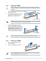
2.4 System memory .........................................................................................2-9
2.4.1 Installing a DIMM ...................................................................... 2-11
2.4.2 Removing a DIMM .................................................................... 2-11
2.5 Expansion slots ........................................................................................2-12
2.5.1 Installing an expansion card......................................................2-12
2.5.2 Configuring an expansion card ................................................. 2-12
2.5.3 Interrupt assignments................................................................2-13
2.5.4 Slot locations ............................................................................. 2-14
2.5.5 Installing an M.2 module ........................................................... 2-15
2.5.6 (optional) Installing the PFR module ......................................... 2-16
2.6 Jumpers ....................................................................................................2-17
2.7 Onboard LEDs .......................................................................................... 2-24
2.8 Connectors ...............................................................................................2-28
2.8.1 Rear panel connectors .............................................................. 2-28
2.8.2 Internal connectors....................................................................2-29

iv
Chapter 3: Powering Up
3.1 Starting up for the first time ......................................................................3-2
3.2 Powering off the computer ........................................................................3-3
3.2.1 Using the OS shut down function ................................................ 3-3
3.2.2 Using the dual function power switch .......................................... 3-3
Chapter 4: BIOS Setup
4.1 Managing and updating your BIOS ..........................................................4-2
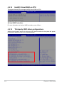
4.1.1 ASUS CrashFree BIOS 3 utility................................................... 4-2
4.1.2 ASUS EZ Flash Utility ................................................................. 4-3
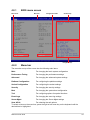
4.2 BIOS setup program ..................................................................................4-4
4.2.1 BIOS menu screen ...................................................................... 4-5
4.2.2 Menu bar ..................................................................................... 4-5
4.3 Main menu ..................................................................................................4-7
4.4 Performance Tuning menu ........................................................................4-8
4.5 Advanced menu .......................................................................................4-10
4.5.1 Trusted Computing.................................................................... 4-11
4.5.2 ACPI Settings ............................................................................ 4-11
4.5.3 Redfish Host Interface Settings................................................. 4-11
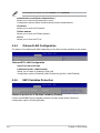
4.5.4 Onboard LAN Configuration ...................................................... 4-12
4.5.5 UEFI Variables Protection ......................................................... 4-12
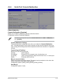
4.5.6 Serial Port Console Redirection ................................................ 4-13
4.5.7 SIO Configuration......................................................................4-15
4.5.8 PCI Subsystem Settings ........................................................... 4-16
4.5.9 USB Configuration .................................................................... 4-17
4.5.10 Network Stack Configuration..................................................... 4-17
4.5.11 NVMe Configuration .................................................................. 4-18
4.5.12 APM Configuration .................................................................... 4-19
4.5.13 Tls Auth Configuration............................................................... 4-19
4.5.14 Intel(R) Virtual RAID on CPU .................................................... 4-20
4.5.15 Third-party UEFI driver configurations ...................................... 4-20
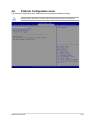
4.6 Platform Configuration menu .................................................................4-21
4.6.1 PCH-IO Configuration ............................................................... 4-22
4.6.2 Miscellaneous Configuration ..................................................... 4-22
4.6.3 Server ME Configuration ........................................................... 4-23
4.6.4 Runtime Error Logging .............................................................. 4-24

v
4.7 Socket Configuration menu ....................................................................4-25
4.7.1 Processor Configuration............................................................ 4-26
4.7.2 Common RefCode Configuration .............................................. 4-31
4.7.3 Uncore Configuration ................................................................ 4-31
4.7.4 Memory Configuration ............................................................... 4-32
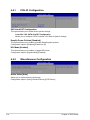
4.7.5 IIO Configuration ....................................................................... 4-36
4.7.6 Advanced Power Management Configuration........................... 4-36
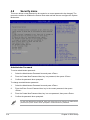
4.8 Security menu ..........................................................................................4-40
4.9 Boot menu ................................................................................................4-43
4.10 Tool menu ................................................................................................. 4-44
4.11 Event Logs menu .....................................................................................4-45
4.11.1 Change Smbios Event Log Settings ......................................... 4-45
4.11.2 View Smbios Event Log ............................................................ 4-46
4.12 Server Mgmt menu ...................................................................................4-47
4.12.1 System Event Log ..................................................................... 4-48
4.12.2 FRU Information ........................................................................ 4-48
4.12.3 BMC network configuration ....................................................... 4-49
4.12.4 View System Event Log ............................................................ 4-51
4.13 Exit menu .................................................................................................. 4-52
Chapter 5: RAID Configuration
5.1 Setting up RAID ..........................................................................................5-2
5.1.1 RAID definitions .......................................................................... 5-2
5.1.2 Installing hard disk drives ............................................................ 5-2
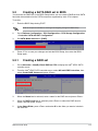
5.2 Creating a SATA RAID set in BIOS ........................................................... 5-3
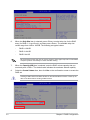
5.2.1 Creating a RAID set ....................................................................................5-3
5.2.2 Deleting a RAID set.....................................................................5-5
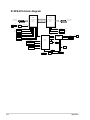
Appendix
Z13PE-D16 block diagram ...................................................................................... A-2
Q-Code table ............................................................................................................ A-3
Notices .................................................................................................................... A-7
Service and Support ............................................................................................. A-11

vi
Safety information
Electrical safety
• To prevent electrical shock hazard, disconnect the power cable from the electrical
outlet before relocating the system.
• When adding or removing devices to or from the system, ensure that the power cables
for the devices are unplugged before the signal cables are connected. If possible,
disconnect all power cables from the existing system before you add a device.
• Before connecting or removing signal cables from the motherboard, ensure that all
power cables are unplugged.
• Seek professional assistance before using an adapter or extension cord. These devices
could interrupt the grounding circuit.
• Make sure that your power supply is set to the correct voltage in your area. If you are
not sure about the voltage of the electrical outlet you are using, contact your local
power company.
• If the power supply is broken, do not try to fix it by yourself. Contact a qualified service
technician or your retailer.
Operation safety
• Before installing the motherboard and adding devices on it, carefully read all the
manuals that came with the package.
• Before using the product, make sure all cables are correctly connected and the power
cables are not damaged. If you detect any damage, contact your dealer immediately.
• To avoid short circuits, keep paper clips, screws, and staples away from connectors,
slots, sockets and circuitry.
• Avoid dust, humidity, and temperature extremes. Do not place the product in any area
where it may become wet.
• Place the product on a stable surface.
• If you encounter technical problems with the product, contact a qualified service
technician or your retailer.

vii
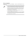
Conventions used in this guide
To ensure that you perform certain tasks properly, take note of the following symbols used
throughout this manual.
DANGER/WARNING: Information to prevent injury to yourself when trying to
complete a task.
CAUTION: Information to prevent damage to the components when trying to
complete a task.
IMPORTANT: Instructions that you MUST follow to complete a task.
NOTE: Tips and additional information to help you complete a task.
Typography
Bold text Indicates a menu or an item to select.
Italics
Used to emphasize a word or a phrase.
<Key> Keys enclosed in the less-than and greater-than sign means
that you must press the enclosed key.
Example: <Enter> means that you must press the Enter or
Return key.
<Key1> + <Key2> + <Key3> If you must press two or more keys simultaneously, the key
names are linked with a plus sign (+).
Example: <Ctrl> + <Alt> + <Del>
Command
Means that you must type the command exactly as shown,
then supply the required item or value enclosed in brackets.
Example: At DOS prompt, type the command line:
format A:/S

viii
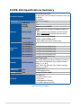
Processor Support
2 x Socket (LGA 4677)
4th Gen Intel® Xeon® Scalable Processors Family (up
to 350W)
UPI 16 GT/s
Core Logic Intel® C741 Chipset
Memory
Total Slots 16
Voltage 1.1V
Capacity Maximum up to 4096GB
Memory Type
DDR5 4800/4400 RDIMM/LRDIMM/NVDIMM/3DS
DIMM
* Memory frequency support depends on the CPU installed.
Refer to www.asus.com for detailed memory AVL & CPU
Support list.
Memory Size
16GB, 32GB, 64GB (RDIMM)
128GB, 256GB (RDIMM-3DS)
* Refer to ASUS server AVL for the latest update
Expansion
Slots
Total PCI/PCI-X/
PCI-E/PIKE Slots 6
Slot Location 1 1 x PCI-E x16 (x16 Gen5 Link)
Slot Location 2 1 x PCI-E x16 (x16 Gen5 Link)
Slot Location 3 1 x PCI-E x16 (x16 Gen5 Link)
Slot Location 4 1 x PCI-E x16 (x16 Gen5 Link)
Slot Location 5 1 x PCI-E x16 (x16 Gen5 Link)
Slot Location 6 1 x PCI-E x16 (x8 Gen5 Link)
Storage SATA Controller
Intel® C741 PCH:
10 x SATA 6Gb/s ports (8 by 2 Slimline Connector)
Intel® RSTe (for Windows only; Support software
RAID 0, 1, 10 & 5)
Intel® VROC (for Windows only; Support software
RAID 0, 1, 10 & 5)
Networking LAN 2 x Intel® X710
1 x Management Port
Graphic VGA Aspeed AST2600 64MB
I/O Ports
1 x COM port
2 x USB 3.2 Gen 1 ports
1 x VGA port
1 x Management LAN port
2 x 10GbE LAN ports (RJ45)
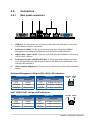
Z13PE-D16 Specifications Summary
(continued on the next page)

ix
Specifications are subject to change without notice.
Onboard I/O Connectors
1 x TPM header
1 x 24-pin SSI Power connector
2 x 8-pin SSI 12V connectors
1 x USB 3.2 Gen 1 header (supports up to 2 USB 3.2
Gen 1 devices)
1 x USB 2.0 header (supports up to 2 USB 2.0
devices)
8 x Fan headers
1 x SMBus header
1 x Chassis Intrusion header
2 x Front LAN LEDs
2 x NGFF Type (1 x 2280, 1 x 22110)
1 x VROC Key connector
OS Support Please find the latest OS support from
https://www.asus.com/event/Server/OS_support_list/
OS.html
Management
Solution
Software ASUS Control Center (Classic)
Out of Band
Remote
Management
ASMB11-iKVM for KVM-over-IP (Optional)
Dimension E-ATX, 12 in. x 13 in.
Environment
Operation temperature:
10oC ~ 35oC (50oF ~ 95oF)
Non operation temperature:
-40oC ~ 70oC (-40oF ~ 158oF)
Non operation humidity:
20% ~ 90% (Non condensing)

x

1
Product Introduction
This chapter describes the motherboard features and the new
technologies it supports.
Chapter 1: Product Introduction

1-2 Chapter 1: Product Introduction
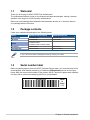
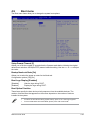
1.1 Welcome!
Thank you for buying an ASUS Z13PE-D16 motherboard!
The motherboard delivers a host of new features and latest technologies, making it another
standout in the long line of ASUS quality motherboards!
Before you start installing the motherboard and hardware devices on it, check the items in
your package with the list below.
1.2 Package contents
Check your motherboard package for the following items.
If any of the above items is damaged or missing, contact your retailer.
Items Standard Gift Box Pack Standard Bulk Pack
Motherboard 1 x Z13PE-D16 1 x Z13PE-D16
I/O Shield 1 x I/O Shield 1 x I/O Shield
Cables 2 x SATA Cables
2 x Slimline SAS to SATA Cables -
Accessory 2 x M.2 screw 2 x M.2 screw
Packaging Qty. 1 pc per carton 10 pcs per carton
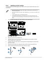
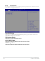
1.3 Serial number label
Before requesting support from the ASUS Technical Support team, you must take note of the
motherboard's serial number containing 12 characters xxSxxxxxxxxx shown as the figure
below. With the correct serial number of the product, ASUS Technical Support team members
can then offer a quicker and satisfying solution to your problems.
xxSxxxxxxxxx
Made
in
China
合格
Z13PE-D16

2
Hardware Information
This chapter lists the hardware setup procedures that you have
to perform when installing system components. It includes
description of the jumpers and connectors on the motherboard.
Chapter 2: Hardware Information

2-2 Chapter 2: Hardware Information
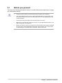
2.1 Before you proceed
Take note of the following precautions before you install motherboard components or change
any motherboard settings.
• Unplug the power cord from the wall socket before touching any component.
• Use a grounded wrist strap or touch a safely grounded object or a metal object, such
as the power supply case, before handling components to avoid damaging them due
to static electricity.
• Hold components by the edges to avoid touching the ICs on them.
• Whenever you uninstall any component, place it on a grounded antistatic pad or in the
bag that came with the component.
• Before you install or remove any component, ensure that the power supply is switched
off or the power cord is detached from the power supply. Failure to do so may cause
severe damage to the motherboard, peripherals, and/or components.

ASUS Z13PE-D16 2-3
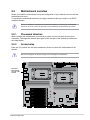
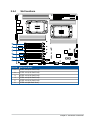
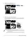
2.2 Motherboard overview
Before you install the motherboard, study the configuration of your chassis to ensure that the
motherboard fits into it.
To optimize the motherboard features, we highly recommend that you install it in an EATX
compliant chassis.
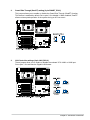
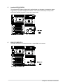
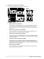
2.2.1 Placement direction
When installing the motherboard, ensure that you place it into the chassis in the correct
orientation. The edge with external ports goes to the rear part of the chassis as indicated in
the image below.
2.2.2 Screw holes
Place ten (10) screws into the holes indicated by circles to secure the motherboard to the
chassis.
DO NOT overtighten the screws! Doing so can damage the motherboard.
Ensure to unplug the chassis power cord before installing or removing the motherboard.
Failure to do so can cause you physical injury and damage motherboard components!
Place this
side towards
the rear of the
chassis

2-4 Chapter 2: Hardware Information
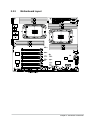
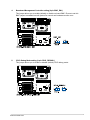
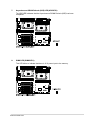
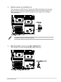
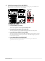
2.2.3 Motherboard layout

ASUS Z13PE-D16 2-5
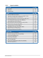
2.2.4 Layout contents
Slots/Sockets Page
1. CPU socket 2-7
2. DIMM slots 2-9
3. Expansion slots 2-12
Jumpers Page
1. Clear RTC RAM (3-pin CLRTC1) 2-17
2. Smart Ride Through (SmaRT) setting (3-pin SMART_PSU1) 2-18
3. LAN Controller settings (3-pin LAN_SW1-2) 2-18
4. Baseboard Management Controller setting (3-pin BMC_EN1) 2-19
5. CPLD Debug Mode setting (3-pin CPLD_DEBUG1) 2-19
6. CPLD setting (3-pin CPLD_UPDATE1) 2-20
7. ME Firmware Force Recovery setting (3-pin ME_RCVR1) 2-20
8. VGA Controller setting (3-pin VGA_SW1) 2-21
9. RM Debug setting (3-pin RM_DEBUG1) 2-21
10. SATADOM power setting (3-pin DOM1_PWR1) 2-22
11. DMLAN setting (3-pin DM_IP_SEL1) 2-22
12. ME Security setting (3-pin PCH_MFG1) 2-23
Onboard LEDs Page
1. Standby Power LED (SBPWR1) 2-24
2. Processor Catastrophic Error LED (CATERR1) 2-24
3. Q-Code LED (PORT80_LED1) 2-25
4. Message LED (MESLED1) 2-25
5. Location LED (LOCLED1) 2-26
6. BMC LED (BMCLED1) 2-26
7. Asynchronous DRAM Refresh (ADR) LED (ADRLED1) 2-27
8. DIMM LED (DIMMLED1) 2-27

2-6 Chapter 2: Hardware Information
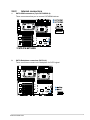
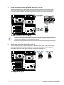
Rear panel connectors Page
1. Video Graphics Adapter port 2-28
2. RJ-45 port for iKVM 2-28
3. USB 3.2 Gen 1 ports 1 and 2 2-28
4. RJ-45 ports for Intel® LOM X710AT LAN 1-2 2-28
5. COM port 2-28
Internal connectors Page
1. SATA DOM connectors (7-pin SATADOM1-2) 2-29
2. SATA Backplane connectors (SATA1-2) 2-29
3. MCIOPCIE connectors (MCIOPCIE_P1-2) 2-30
4. USB 3.2 Gen 1 connector (20-1 pin U32G1_34) 2-30
5. USB 2.0 connector (10-1 pin USB_8_12) 2-31
6. BMC Debug UART connector (3-pin BMC_DEBUGUART1) 2-31
7. Power connectors (24-pin EATXPWR; 8-pin CPU_12V1-2) 2-32
8. GPU Power connectors (8-pin GPU_12V1-2) 2-32
9. Fan connectors (4-pin CPU_FAN1-2, SYS_FAN1-6) 2-33
10. VPP_I2C connector (10-1 pin VPP_I2C1) 2-33
11. System panel connector (20-1 pin PANEL) 2-34
12. Auxiliary Panel connector (20-2 pin AUX_PANEL1) 2-35
13. VROC Key connector (4-pin VROC_KEY1) 2-36
14. Trusted Platform Module connector (14-1 pin SPI_TPM) 2-36
15. Chassis Intrusion (2-pin INTRUSION1) 2-37
16. Power Supply SMBus connector (5-pin PSUSMB1) 2-37
17. M.2 slot (M2_SLOT1-2) 2-38
18. CPLD Debug connector (6-pin CPLD_JTAG1) 2-38
19. Platform Firmware Resilience (PFR) module connector (ROT_CON) 2-39
20. PSYS_SENSE connector (3-pin PSYS_SENSE1) 2-39

ASUS Z13PE-D16 2-7
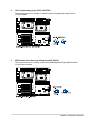
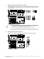
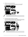
2.3 Central Processing Unit (CPU)
The motherboard comes with two surface mount LGA 4677 sockets designed for the 4th Gen
Intel® Xeon® Scalable Processors Family Series.
Ensure that you install the correct CPU designed for LGA 4677 socket only. DO NOT install
a CPU designed for other sockets on the LGA 4677 socket.
• Upon purchase of the motherboard, ensure that the PnP cap is on the socket and
the socket contacts are not bent. Contact your retailer immediately if the PnP cap
is missing, or if you see any damage to the PnP cap/socket contacts/motherboard
components. ASUS will bear the cost of repair only if the damage is shipment/transit-
related.
• Keep the cap after installing the motherboard. ASUS will process Return Merchandise
Authorization (RMA) requests only if the motherboard comes with the PnP cap on the
socket.
• The product warranty does not cover damage to the socket contacts resulting from
incorrect CPU installation/removal, or misplacement/loss/incorrect removal of the PnP
cap.

2-8 Chapter 2: Hardware Information
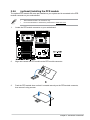
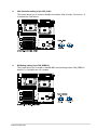
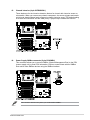
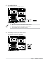
2.3.1 Installing the CPU and heatsink
The CPU and CPU Carrier fits in
only one correct orientation. DO
NOT force the CPU and CPU
Carrier into the socket to prevent
damaging the CPU pins on the
socket.
Ensure the triangle mark on the
CPU is located in the same corner
as the CPU socket.
Intel® recommends using a torque
driver with a T-30 bit and a torque
value of 8 lbf-in to prolong the
longevity of all PEEK nuts after the
quality of the load post is corrected.
La pagina si sta caricando...
La pagina si sta caricando...
La pagina si sta caricando...
La pagina si sta caricando...
La pagina si sta caricando...
La pagina si sta caricando...
La pagina si sta caricando...
La pagina si sta caricando...
La pagina si sta caricando...
La pagina si sta caricando...
La pagina si sta caricando...
La pagina si sta caricando...
La pagina si sta caricando...
La pagina si sta caricando...
La pagina si sta caricando...
La pagina si sta caricando...
La pagina si sta caricando...
La pagina si sta caricando...
La pagina si sta caricando...
La pagina si sta caricando...
La pagina si sta caricando...
La pagina si sta caricando...
La pagina si sta caricando...
La pagina si sta caricando...
La pagina si sta caricando...
La pagina si sta caricando...
La pagina si sta caricando...
La pagina si sta caricando...
La pagina si sta caricando...
La pagina si sta caricando...
La pagina si sta caricando...
La pagina si sta caricando...
La pagina si sta caricando...
La pagina si sta caricando...
La pagina si sta caricando...
La pagina si sta caricando...
La pagina si sta caricando...
La pagina si sta caricando...
La pagina si sta caricando...
La pagina si sta caricando...
La pagina si sta caricando...
La pagina si sta caricando...
La pagina si sta caricando...
La pagina si sta caricando...
La pagina si sta caricando...
La pagina si sta caricando...
La pagina si sta caricando...
La pagina si sta caricando...
La pagina si sta caricando...
La pagina si sta caricando...
La pagina si sta caricando...
La pagina si sta caricando...
La pagina si sta caricando...
La pagina si sta caricando...
La pagina si sta caricando...
La pagina si sta caricando...
La pagina si sta caricando...
La pagina si sta caricando...
La pagina si sta caricando...
La pagina si sta caricando...
La pagina si sta caricando...
La pagina si sta caricando...
La pagina si sta caricando...
La pagina si sta caricando...
La pagina si sta caricando...
La pagina si sta caricando...
La pagina si sta caricando...
La pagina si sta caricando...
La pagina si sta caricando...
La pagina si sta caricando...
La pagina si sta caricando...
La pagina si sta caricando...
La pagina si sta caricando...
La pagina si sta caricando...
La pagina si sta caricando...
La pagina si sta caricando...
La pagina si sta caricando...
La pagina si sta caricando...
La pagina si sta caricando...
La pagina si sta caricando...
La pagina si sta caricando...
La pagina si sta caricando...
La pagina si sta caricando...
La pagina si sta caricando...
La pagina si sta caricando...
La pagina si sta caricando...
La pagina si sta caricando...
La pagina si sta caricando...
La pagina si sta caricando...
La pagina si sta caricando...
La pagina si sta caricando...
La pagina si sta caricando...
La pagina si sta caricando...
La pagina si sta caricando...
La pagina si sta caricando...
La pagina si sta caricando...
La pagina si sta caricando...
La pagina si sta caricando...
La pagina si sta caricando...
La pagina si sta caricando...
La pagina si sta caricando...
La pagina si sta caricando...
La pagina si sta caricando...
La pagina si sta caricando...
La pagina si sta caricando...
La pagina si sta caricando...
La pagina si sta caricando...
La pagina si sta caricando...
-
 1
1
-
 2
2
-
 3
3
-
 4
4
-
 5
5
-
 6
6
-
 7
7
-
 8
8
-
 9
9
-
 10
10
-
 11
11
-
 12
12
-
 13
13
-
 14
14
-
 15
15
-
 16
16
-
 17
17
-
 18
18
-
 19
19
-
 20
20
-
 21
21
-
 22
22
-
 23
23
-
 24
24
-
 25
25
-
 26
26
-
 27
27
-
 28
28
-
 29
29
-
 30
30
-
 31
31
-
 32
32
-
 33
33
-
 34
34
-
 35
35
-
 36
36
-
 37
37
-
 38
38
-
 39
39
-
 40
40
-
 41
41
-
 42
42
-
 43
43
-
 44
44
-
 45
45
-
 46
46
-
 47
47
-
 48
48
-
 49
49
-
 50
50
-
 51
51
-
 52
52
-
 53
53
-
 54
54
-
 55
55
-
 56
56
-
 57
57
-
 58
58
-
 59
59
-
 60
60
-
 61
61
-
 62
62
-
 63
63
-
 64
64
-
 65
65
-
 66
66
-
 67
67
-
 68
68
-
 69
69
-
 70
70
-
 71
71
-
 72
72
-
 73
73
-
 74
74
-
 75
75
-
 76
76
-
 77
77
-
 78
78
-
 79
79
-
 80
80
-
 81
81
-
 82
82
-
 83
83
-
 84
84
-
 85
85
-
 86
86
-
 87
87
-
 88
88
-
 89
89
-
 90
90
-
 91
91
-
 92
92
-
 93
93
-
 94
94
-
 95
95
-
 96
96
-
 97
97
-
 98
98
-
 99
99
-
 100
100
-
 101
101
-
 102
102
-
 103
103
-
 104
104
-
 105
105
-
 106
106
-
 107
107
-
 108
108
-
 109
109
-
 110
110
-
 111
111
-
 112
112
-
 113
113
-
 114
114
-
 115
115
-
 116
116
-
 117
117
-
 118
118
-
 119
119
-
 120
120
-
 121
121
-
 122
122
-
 123
123
-
 124
124
-
 125
125
-
 126
126
-
 127
127
-
 128
128


Asus Z13PE-D16 Manuale utente
- Categoria
- Schede madri
- Tipo
- Manuale utente
in altre lingue
- English: Asus Z13PE-D16 User manual
Documenti correlati
-
Asus RS500A-E12-RS12U Manuale utente
-
-
-
-
-
Asus Pro WS W790-ACE Manuale utente
-
Asus P12R-M/10G-2T Manuale utente
-
Asus Prime Z390-P Manuale utente
-
-