
Multi-Tech Model
IAC-F696
Single Board Computer for
CommPlete 4000 Server
USER'S MANUAL

Copyright and Technical Support
Multi-Tech Systems, Inc. Single Board Computer IAC-F696 User’s Guide (S000349A) 2
CommPlete 400 Single Board Computer (IAC-F696)
User Guide
PN S000349A
Copyright
This publication may not be reproduced, in whole or in part, without prior expressed written permission from
Multi-Tech Systems, Inc. All rights reserved.
Copyright © 2002-2004, by Multi-Tech Systems, Inc.
Multi-Tech Systems, Inc. makes no representations or warranties with respect to the contents hereof and
specifically disclaim any implied warranties of merchantability or fitness for any particular purpose. Furthermore,
Multi-Tech Systems, Inc. reserves the right to revise this publication and to make changes from time to time in
the content hereof without obligation of Multi-Tech Systems, Inc. to notify any person or organization of such
revisions or changes.
Revisions
Revision Level Date Description
A 05/21/04 Initial release.
Patents
This device covered by one or more of the following patents: 5.301.274, 5.309.562, 5.355.365, 5.452.289, and
5.453.986.
Other Patents Pending.
Trademarks
The Multi-Tech logo is a Trademark of Multi-Tech Systems, Inc.
Microsoft and Windows are registered trademarks or trademarks of Microsoft Corporation in the United States
and/or other countries. All other trademarks are owned by their respective companies.
The following are trademarks or registered trademarks of their respective companies and companies.
IBM, AMD, V1A C3, Award, AMI, PC/104, PICMG, ALI, DMC, SMC, Winbond
Pentium
®
, Celeron
TM
are registered trademark of Intel Corporation.
NetWare is a registered trademark of Novell, Inc.
SCO is a registered trademark of Santa Cruz Operation, Inc.
UNIX is a registered trademark of X/Open Company, Ltd.
World Headquarters
Multi-Tech Systems, Inc.
2205 Woodale Drive
Mounds View, Minnesota 55112
Phone: 763-785-3500 or 800-328-9717
Fax: 763-785-9874
Technical Support
Country By Email By Phone
Rest of the World: oemsale[email protected] (763) 717-5863
Internet Address: http://www.multitech.com

Table of Contents
Multi-Tech Systems, Inc. Single Board Computer IAC-F696 User’s Guide (S000349A) 3
TABLE OF CONTENTS
Chapter 1 – General Information ..................................................................................................................................4
Introduction ................................................................................................................................................................4
Features.....................................................................................................................................................................4
Technical Specification ..............................................................................................................................................5
IAC-F696 Series .....................................................................................................................................................5
Chapter 2 – Installation .................................................................................................................................................6
Hardware Setup and Installation ................................................................................................................................6
System Memory Installation....................................................................................................................................6
Compact Flash Installation......................................................................................................................................6
Jumper Settings and Connectors...............................................................................................................................7
Board Outline..........................................................................................................................................................7
I/O Connector Summary .......................................................................................................................................12
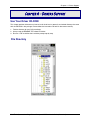
Chapter 3 – BIOS Setup...............................................................................................................................................26
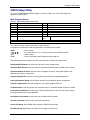
Running Phoenix AWARD BIOS..............................................................................................................................26
Entering Setup ......................................................................................................................................................26
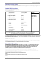
CMOS Setup Utility ..................................................................................................................................................27
Main Program Screen ...........................................................................................................................................27
Standard CMOS Setup ............................................................................................................................................28
Standard CMOS Setup Screen .............................................................................................................................28
Primary Master/Primary Slave ..............................................................................................................................28
BIOS Features Setup...............................................................................................................................................30
BIOS Features Setup Screen................................................................................................................................30
Chipset Features Setup ...........................................................................................................................................32
Chipset Features Setup Screen............................................................................................................................32
Integrated Peripherals..............................................................................................................................................34
Integrated Peripherals Setup Screen ....................................................................................................................34
Power Management Setup.......................................................................................................................................36
Power Management Setup Screen .......................................................................................................................36
PnP/PCI Configuration .............................................................................................................................................37
PnP/PCI Configuration Setup Screen ...................................................................................................................37
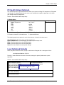
PC Health Status (Optional).....................................................................................................................................39
Load Optimized Defaults..........................................................................................................................................39
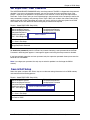
Set Supervisor / User Password ..............................................................................................................................40
Save & Exit Setup ....................................................................................................................................................40
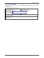
Exit Without Saving..................................................................................................................................................41
Chapter 4 – Drivers Support .......................................................................................................................................42
Use Your Driver CD-ROM........................................................................................................................................42
File Directory............................................................................................................................................................42
Appendix A – Watchdog Timer...................................................................................................................................43
Appendix B – Warranty ...............................................................................................................................................44
Multi-Tech Warranty Statement ............................................................................................................................44
Repair Procedures for U.S. and Canadian Customers .........................................................................................44
Repair Procedures for International Customers (Outside U.S.A. and Canada).....................................................44
Repair Procedures for International Distributors ...................................................................................................45
Replacement Parts ...............................................................................................................................................45
Index .............................................................................................................................................................................46

Chapter 1 – General Information
Multi-Tech Systems, Inc. Single Board Computer IAC-F696 User’s Guide (S000349A) 4
Chapter 1 – GENERAL INFORMATION
Introduction
IAC-F696 With its rich AGP V1.0 Compliant 2X integrated graphics capabilities, flexible FSB settings,
and support for PC133 DRAM, delivers excellent levels of scalability and performance on a cost-
effective, High integrated platform designed for the specific needs of the Automation, DVR, Information
PC, and Internet Appliance market segments.
Low power VIA CPU + VIA Apollo PLE133P = Ultimate Value Combination
IAC-F696 optimizes the performance of the VIA Low power Processor while its integrated AGP 2X
graphics engine delivers rich graphics capabilities for running 2D/3D software and Internet applications.
Its highly scaleable asynchronous bus design also makes it the ideal solution for VIA low power
processors running at 100/133MHz FSB speeds. With an advanced memory controller architecture, the
IAC-F696 supports up to 1.5GB of high-speed PC133 SDRAM. These advanced memory technologies
provide the bandwidth and performance necessary for even the most demanding Internet and 3D
graphics applications. Further integrated CPU & multimedia & connectivity features that help minimize
the cost of building automation and Internet Appliances without sacrificing features and performance
include two Fast Ethernet controllers, integrated AGP 2X graphics, AC’97 audio, Super I/O, and
advanced power management.
In addition, IAC-F696 features two IDE, one FDD port, two COM ports and one multi-mode parallel port
allows for more devices support and more flexibility. Other standard features include one socket for
Compact Flash, four USB headers and one IrDA header. IAC-F696 has also incorporated Watchdog
Timer that allows for monitoring ability to ensure system stability.
Features
• VIA EBGA 1GHz CPU
• VIA VT8601T North Bridge and VT82C686B South Bridge
• Award BIOS
• Integrated AGP 2X Graphics Engine
• Dual Realtek RTL 8100C 10/100 Base-T Fast Ethernet
• 2 x EIDE, 1 x FDD, 2 x COM, 1 x LPT, Keyboard & Mouse, 4 x USB, 1 x IrDA and 1 x VGA
• Watchdog Timer
• ISA & PCI expansion bus (PICMG)

Chapter 1 – General Information
Multi-Tech Systems, Inc. Single Board Computer IAC-F696 User’s Guide (S000349A) 5
Technical Specification
IAC-F696 Series
CPU
VIA C3 EBGA 1GHz s
Max. Speed
1GHz
L2 Cache
Integrated 192KB Cache (two 64KB L1 Cache and 64KB L2)
Chipset
VIA VT8601T (NB)+VT82C686B (SB)
Processor
System
BIOS
Award licensed BIOS (2M bit Flash ROM)
FSB
100/133MHz
Bus
PCI
32-bit/33 MHz
Technology
PC-100/133
Max.
Capacity
1.5 GB
Memory
Socket
Three 168-pin DIMM
Controller On-board integrated VGA controller
VRAM Share memory up to 8 MB
Graphic
Connector One DB15 (VGA)/VT1631 LVDS connector
Controller Dual Realtek 8100C X 2
Interface 10/100 Base-T (FE)
Ethernet
Connector RJ-45
Mode ATA 100/66/33
EIDE
Channel Two 20x2 Box header, support up to four devices
FDD
One 17x2 Box header, support up to two devices
Serial port
One DB9 (COM1: RS-232) and one 5 x 2 Box header (COM2: RS-232)
Parallel port
One 13 x 2 Box header (SPP/EPP/ECP)
PS/2
One mini-DIN6 PS/2 keyboard/mouse connector and one 5-pin
keyboard wafer
USB
Header for 4 ports (USB 1.1 compliant)
I/O Interface
IrDA
One IrDA compliant Infrared interface
Flash Memory
Disk
CF Type-II at solder side
Health Monitoring
System Temperature Alarm Sensor
Expansion Bus
PCI & ISA (PICMG)
I/O Bracket
COM1 (DB9) + LAN1 (RJ-45) + VGA(DB15) + PS/2(mini DIN)
RTC
Internal RTC with Li battery
Watchdog Timer
16-level time-out intervals
Power
Requirements
Standard ATX/AT Power
Operating
0 °C~60 °C
Temperature
Storage
-20 °C~70 °C
Dimensions
338 x 122 (13.3” x 4.8”)
EMI/EMS
EN 50081-1/1994>EN 55022/1997>
EN 61000-3-2/1995>EN 61000-3-3/1995,
EN 50082-1/1994>IEC 1000-4-2/1995,
IEC 1000-4-3/1995, IEC 1000-4-4/1995

Chapter 2 - Installation
Multi-Tech Systems, Inc. Single Board Computer IAC-F696 User’s Guide (S000349A) 6
CHAPTER 2 – INSTALLATION
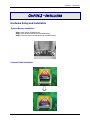
Hardware Setup and Installation
System Memory Installation
Step1: Open latches of DIMM socket.
Step2: Insert the RAM module into the DIMM socket.
Step3: Press the latches into the notches of the RAM module.
Compact Flash Installation

Chapter 2 - Installation
Multi-Tech Systems, Inc. Single Board Computer IAC-F696 User’s Guide (S000349A) 7
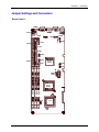
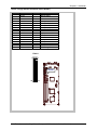
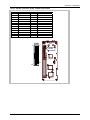
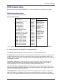
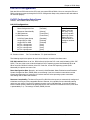
Jumper Settings and Connectors
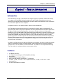
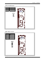
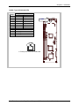
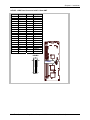
Board Outline
COMA1
LANB1
USBF2
KCN1
PKM1
VGAA1
SC2T2
COMB1
LNB1
SM1
PLRS1
LPTA1
IDEB1
FDCA1
SBVB1
ATXD1
USBF1
FAN1
SCF1
PSW1
LVDSE
CMOS
1
VLCD1
DIMMA3
DIMMA2
DIMMA1
North
Bridge
South
Bridge
IDEB2
KBPW1
SC2T1 IRDA1
FAN2 CPU

Chapter 2 - Installation
Multi-Tech Systems, Inc. Single Board Computer IAC-F696 User’s Guide (S000349A) 8
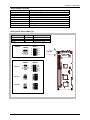
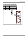
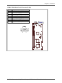
Jumper Settings Summary
Jumper
Function
SC2T1/SC2T2 Select COM2 Type
VLCD1 Select Panel Voltage
CMOS1 Clear CMOS Data
PLRS1 Power LED, HD LED, Reset, Speaker Connector
SCF1 Master/Slave Select
KBPW1 PS/2 Keyboard/Mouse
SBVB1 Select power mode
SLVA1 12/24 Bit Input Mode Select
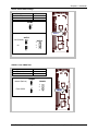
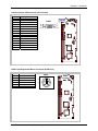
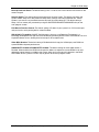
SC2T1/SC2T2: Select COM2 Type
COM2 TYPE SC2T1 SC2T2
RS-232 (Default) 1-2 1-5,2-6,3-7,4-8
RS-422 3-4 5-9,6-10,7-11,8-12
RS-485 5-6 5-9,6-10,7-11,8-12
RS-422
RS-485
RS-232
9
10
11
12
SC2T2
1
2
3
4
SC2T1
1
3
5
2
4
6
SC2T1
1
3
5
2
4
6
Default:
1
2
3
4
9
10
11
12
SC2T2
SC2T1
SC2T2

Chapter 2 - Installation
Multi-Tech Systems, Inc. Single Board Computer IAC-F696 User’s Guide (S000349A) 9
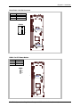
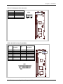
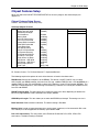
VLCD1: Select Panel Voltage
Panel Voltage VLCD1
+3.3 V (Default) 1-2
+5 V 2-3
CMOS1: Clear CMOS Data
Description CMOS1
Normal (Default) 1-2
Clear CMOS 2-3
Clear CMOS1
Normal (Default)
CMOS1
1
2
3
CMOS1
1
2
3
1
2
3
CMOS1
Default:
V
LCD1
3
2
1
V
LCD1
3.3V (Default)
3
2
1
V
LCD1
3
2
1
5V
3
2
1
VLCD1

Chapter 2 - Installation
Multi-Tech Systems, Inc. Single Board Computer IAC-F696 User’s Guide (S000349A) 10
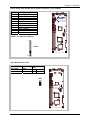
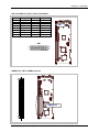
PLRS1: Power LED, HD LED, Reset, Speaker Connector (11 Pin 2.54mm)
Pin No. Description
1 Power LED +
2 Power LED +
3 GND
4 HDD LED +
5 HDD LED -
6 RESET SW +
7 RESET SW – (GND)
8 External Speaker -
9 Internal Buzzer -
10 NC
11 External Speaker +
SCF1: Master/Slave Select
Compact
Flash Card
ATA Disk
Chip
SCF1
Master Slave 1-2
Slave Master 2-3 (Default)
Default : 8-9 (ON) Internal Buzzer
11
1
PLRS1
PLRS1
SCF1
1
3
SCF1

Chapter 2 - Installation
Multi-Tech Systems, Inc. Single Board Computer IAC-F696 User’s Guide (S000349A) 11
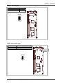
KBPW1: 1x3 Pin 2.54mm
PS/2 Keyboard/Mouse KBPW1
+5V (Default) 1-2
+5V STANDBY 2-3
SBVB1: Select power mode
MODE SBVB1
AT 1-2
ATX 2-3
KBPW
1
KBPW1
1
3
SBVB1
SBVB1
1
3

Chapter 2 - Installation
Multi-Tech Systems, Inc. Single Board Computer IAC-F696 User’s Guide (S000349A) 12
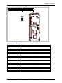
SLVA1: 12/24 Bit Input Mode Select
Bit Input Mode Select SLVA1
24 bits Mode 1-2 (Default)
12 bits Mode 2-3
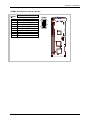
I/O Connector Summary
CONNECTOR FUNCTION
ATXD1
For ATX Function
IRDA1 IRDA1 Connector
USBF1/ USBF2 USB Port #1 & #2 Connector (2¯5 Pin 2.54mm)
FAN1/ FAN2 3 Pin FAN Connector
PSW1 ATX Power Button
IDEB1 / IDEB2 IDE Interface Connector (40Pin 2.54mm Pitch Header)
FDCA1 Floppy Interface Connector (34 Pin Header)
LPTA1 Parallel Connector (26 Pin 2.54mm Pitch Header)
COMA1 RS-232 Serial Port #1 Connector (D-Sub)
COMB1 Serial Port #2 Connector (Header)
LANB1 Type 2 (RJ-45 with LED)
VGAA1 External VGA Connector (15 Pin D-Sub)
PKM1 PS/2 Keyboard & Mouse Connector (6P Mini Din)
KCN1 5 Pin Keyboard Cable Connector
LNB1 LAN 2¯8 Pin 2.0mm (Female/ Male)
SM1 Sound/ Mouse (2¯8 Pin 2.0mm Female/ Male)
DIMMA1/2/3 168 Pin DIMM Connector
LVDSE1 LVDS Panel Connector 2¯20P 1.25mm SMT
SLVA1
SLVA1
1
3

Chapter 2 - Installation
Multi-Tech Systems, Inc. Single Board Computer IAC-F696 User’s Guide (S000349A) 13
ATXD1: For ATX Function
Pin No. Description
1 PSON
2 GND
3 +5V STANDBY
IRDA1: IRDA1 Connector
Pin No. Description
1 VCC
2 NC
3 IRRX
4 GND
5 IRTX
ATXD1
1
3
ATXD1
IRDA1
5
1
IRDA1

Chapter 2 - Installation
Multi-Tech Systems, Inc. Single Board Computer IAC-F696 User’s Guide (S000349A) 14
USBF1/USBF2: USB Port #1 & #2 Connector 2x5 Pin 2.54mm
Pin
No.
Description
Pin
No.
Description
1 USB_VCC 2 Ground
3 Key 4 USBD1+/3+
5 USBD0-/2- 6 USBD1-/3-
7 USBD0+/2+ 8 Key
9 Ground 10 USB_VCC
1
9
USBF1
2
10
USBF2
USBF1

Chapter 2 - Installation
Multi-Tech Systems, Inc. Single Board Computer IAC-F696 User’s Guide (S000349A) 15
FAN1/FAN2: 3 Pin FAN Connector
Pin No. Description
1 Ground
2 +12V
3 FAN Status
PSW1: For ATX Power Button
Pin No. Description
1 PANSW
2 GND
1
2
FAN1
/
2
1
2
3
FAN1
FAN2
PSW1
PSW1
1
2

Chapter 2 - Installation
Multi-Tech Systems, Inc. Single Board Computer IAC-F696 User’s Guide (S000349A) 16
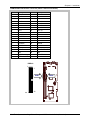
IDEB1/IDEB2: IDE Interface Connector (40Pin 2.54mm Pitch Header)
Pin No. Description Pin No. Description
1 Reset # 2 Ground
3 Data 7 4 Data 8
5 Data 6 6 Data 9
7 Data 5 8 Data 10
9 Data 4 10 Data 11
11 Data 3 12 Data 12
13 Data 2 14 Data 13
15 Data 1 16 Data 14
17 Data 0 18 Data 15
19 Ground 20 KEY
21 DMA REQ# 22 Ground
23 IOW # 24 Ground
25 IOR # 26 Ground
27 IOCHRDY 28 Ground
29 DMA ACK # 30 Ground
31 Interrupt 32 NC
33 SA1 34 PD80P / SD80P
35 SA0 36 SA2
37 HDC CS0 # 38 HDC CS1 #
39 HDD Active LED # 40 Ground
IDEB1/2
1
39
2
40
IDEB1
IDEB2

Chapter 2 - Installation
Multi-Tech Systems, Inc. Single Board Computer IAC-F696 User’s Guide (S000349A) 17
FDCA1: Floppy Interface Connector (34 Pin Header)
Pin No. Description Pin No. Description
1 Ground 2 Density Select
3 Ground 4 KEY
5 Ground 6 DS1
7 Ground 8 Index #
9 Ground 10 Motor Enable A #
11 Ground 12 Drive Select B #
13 Ground 14 Drive Select A #
15 Ground 16 Motor Enable B #
17 Ground 18 Direction #
19 Ground 20 Step #
21 Ground 22 Write Data #
23 Ground 24 Write Gate #
25 Ground 26 Track 0 #
27 Ground 28 Write Protect #
29 NC 30 Read Data #
31 Ground 32 Head Side Select #
33 NC 34 Disk Change #
FDCA1
1
33
2
34
FDCA1

Chapter 2 - Installation
Multi-Tech Systems, Inc. Single Board Computer IAC-F696 User’s Guide (S000349A) 18
LPTA1: Parallel Connector (26 Pin 2.54mm Pitch Header)
Pin No. Description Pin No. Description
1 Strobe # 2 Auto Form Feed
3 Data0 4 Error #
5 Data1 6 Initialize #
7 Data2 8 Printer Select IN #
9 Data3 10 Ground
11 Data4 12 Ground
13 Data5 14 Ground
15 Data6 16 Ground
17 Data7 18 Ground
19 Acknowledge # 20 Ground
21 Busy 22 Ground
23 Paper Empty 24 Ground
25 Printer Select 26 KEY
1
25
2
26
LPTA1
LPTA1

Chapter 2 - Installation
Multi-Tech Systems, Inc. Single Board Computer IAC-F696 User’s Guide (S000349A) 19
COMA1: RS-232 Serial Port #1 Connector (D-Sub)
Pin No. Description
1 Data Carrier Detect (DCDA #)
2 Receive Data (RXDA)
3 Transmit Data (TXDA)
4 Data Terminal Ready (DTRA #)
5 Ground (GND)
6 Data Set Ready (DSRA #)
7 Request To Send (RTSA #)
8 Clear To Send (CTSA #)
9 Ring Indicator (RIA #)
15
COMA1
96
COMA1

Chapter 2 - Installation
Multi-Tech Systems, Inc. Single Board Computer IAC-F696 User’s Guide (S000349A) 20
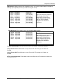
COMB1: Serial Port #2 Connector (Header)
Description
Pin No.
RS-232
1 Data Carrier Detect (DCDB #)
2 Data Set Ready (DSRB #)
3 Receive Data (RXDB)
4 Request To Send (RTSB #)
5 Transmit Data (TXDB)
6 Clear To Send (CTSB #)
7 Data Terminal Ready (DTRB #)
8 Ring Indicator (RIB #)
9 Ground
10 KEY
COMB1
1
9
2
10
COMB1
La pagina si sta caricando...
La pagina si sta caricando...
La pagina si sta caricando...
La pagina si sta caricando...
La pagina si sta caricando...
La pagina si sta caricando...
La pagina si sta caricando...
La pagina si sta caricando...
La pagina si sta caricando...
La pagina si sta caricando...
La pagina si sta caricando...
La pagina si sta caricando...
La pagina si sta caricando...
La pagina si sta caricando...
La pagina si sta caricando...
La pagina si sta caricando...
La pagina si sta caricando...
La pagina si sta caricando...
La pagina si sta caricando...
La pagina si sta caricando...
La pagina si sta caricando...
La pagina si sta caricando...
La pagina si sta caricando...
La pagina si sta caricando...
La pagina si sta caricando...
La pagina si sta caricando...
La pagina si sta caricando...
La pagina si sta caricando...
-
 1
1
-
 2
2
-
 3
3
-
 4
4
-
 5
5
-
 6
6
-
 7
7
-
 8
8
-
 9
9
-
 10
10
-
 11
11
-
 12
12
-
 13
13
-
 14
14
-
 15
15
-
 16
16
-
 17
17
-
 18
18
-
 19
19
-
 20
20
-
 21
21
-
 22
22
-
 23
23
-
 24
24
-
 25
25
-
 26
26
-
 27
27
-
 28
28
-
 29
29
-
 30
30
-
 31
31
-
 32
32
-
 33
33
-
 34
34
-
 35
35
-
 36
36
-
 37
37
-
 38
38
-
 39
39
-
 40
40
-
 41
41
-
 42
42
-
 43
43
-
 44
44
-
 45
45
-
 46
46
-
 47
47
-
 48
48


in altre lingue
- English: Multitech IAC-F696 User manual
Altri documenti
-
DeLOCK 83821 Scheda dati
-
-
DeLOCK 83822 Scheda dati
-
Tyan Tempest i5100W Manuale utente
-
-
-
-
-
-