Abus FTS 3002 Installation and Operation Instructions
- Tipo
- Installation and Operation Instructions

ABUS - Das gute Gefühl der Sicherheit
www.abus.com
D Technische Änderungen vorbehalten. Für Irrtümer und Druckfehler keine Haftung. ABUS © 2010
D Diese Anleitung ist wie folgt untergliedert:
I. Allgemeine Hinweise
II. Einsatzmöglichkeit der FTS 3002
III. Packungsinhalt
IV. Werkzeug
V. Montageanleitung
VI. Bedienung
I. Allgemeine Hinweise
Die Fenster- und Türsicherung FTS 3002 ist nach den strengen
SKG*-Prüfanforderungen geprüft und anerkannt. FTS 3002 bietet
zusätzlichen Schutz gegen unberechtigtes Eindringen in Ihre Räume.
Wir empfehlen, dass pro 1m Fenster-/Türhöhe jeweils eine Zusatz-
sicherung montiert wird.
Die optimale Schutzwirkung erreichen Sie, wenn Sie entsprechend dieser
Montage- und Bedienungsanleitung vorgehen. Die Befestigungsschrauben
sollten zur Vermeidung von Überdrehung mit einem geeigneten Werkzeug
von Hand eingeschraubt und angezogen werden.
Für eventuell auftretende Verletzungen bzw. Schäden, die bei der
Montage und/oder durch unsachgemäße Handhabung entstehen,
übernimmt der Hersteller keine Haftung!
II. Einsatzmöglichkeit der FTS 3002
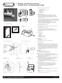
FTS 3002 eignet sich für alle gängigen nach außen öffnenden Fenster
und Türen (Abb. 1).
Die Montage kann auf Holz erfolgen.
Das Fenster/die Tür kann nach rechts oder links öffnen.
FTS 3002 wird grundsätzlich innen auf der Öffnungsseite montiert,
das Schloss auf dem Fensterflügel/Türblatt und das Schließblech
auf dem Rahmen.
III. Packungsinhalt
1 Schließkasten
1 Schließblech
2 Schlüssel
4 Schrauben 4,8 x 38 mm
2 Schrauben 4,2 x 50 mm
1 Montageanleitung
IV. Werkzeuge
Kreuzschlitz-Schraubendreher
Bohrmaschine
Bohrer für Holz: Ø 16 mm, Ø 3,5 mm und Ø 3,0 mm
V. Montageanleitung
Wichtige Hinweise:
Vor der Montage die Einstellung des Fensters/der Tür prüfen und ggf.
Beschläge neu einstellen, damit das Fenster/die Tür einwandfrei öffnet
und schließt. Die Bohrlöchertiefen bzw. die Schraubenlängen müssen
evtl. den örtlichen Gegebenheiten angepasst werden, damit das Austreten
des Bohrers bzw. der Schrauben auf der Rückseite vermieden wird.
Ggf. mit Bohranschlag arbeiten, kürzere Schrauben verwenden oder
vorhandene kürzen. Beim Bohren keine beweglichen Teile, Dichtungen
oder Glasscheiben verletzen.
Montage:
Haube abmontieren (Abb. 2)
Aufschließen und Schraube herausdrehen (1).
Haube verschieben (2) und abnehmen (3).
Riegelelement am Fensterflügel/Türblatt befestigen (Abb. 3)
Riegelelement 7– 8 mm vom Rahmen entfernt positionieren und ausrichten
(Abb. 3a). Löcher „A” anzeichnen und vorbohren (Holz Ø 3,5 mm).
Mit 4 Schrauben Ø 4,8 x 38 mm befestigen.
Schließblech befestigen (Abb. 4)
Riegel mit Drucktaste fest gegen Rahmen drücken, so dass Markierung
entsteht. Loch „B” Ø 16 mm ca. 22 mm tief bohren (Abb. 4a).
Schließblech entsprechend der Schlossgehäusekontur aufsetzen und
zentrisch zum eingedrückten Riegel ausrichten.
Löcher „D” anzeichnen und vorbohren (Holz Ø 3,0 mm).
Mit 2 Schrauben Ø 4,2 x 50 mm befestigen. Riegel eindrücken und
Funktion kontrollieren.
Haube aufsetzen und mit Schraube Ø 3,5 x 9,5 mm befestigen.
Wenn Schraube Ø 3,5 x 9,5 mm nicht benutzt werden kann
(z.B. bei Schiebefenstern usw.), Hohlstift mit Zange o.ä. in Haube
einschieben (Abb. 5). Nicht von Hand, Verletzungsgefahr!
Haube aufsetzen und verschieben bis sie einrastet.
VI. Bedienung
Verriegelung:
Durch Verschieben der Drucktaste rastet der Riegel im Schließwerk ein.
Der Schlüssel wird hierzu nicht benötigt.
Öffnen:
Durch leichtes Drehen des Schlüssels springt der Riegel automatisch
zurück.
Die Sicherung FTS 3002 ist wartungsfrei.
D Montage- und Bedienungsanleitung
für ABUS Fenster- und Türsicherung FTS 3002
B
35
19
47 87
58
20
33,5
1
2
3
Abb./fig./
schéma/afb./ill. 2
FTS 3002
FTS 3002
FTS 3002
FTS 3002
FTS 3002
FTS 3002
Abb./fig./schéma/afb./ill. 1
A
A
A
A
B
Drucktaste
Push botton
Bouton poussoir
Druktoets
Tasto
Riegelelement
Locking element
Grendelelement
Boîtier
Elemento del
chiavistello
7– 8 mm
Abb./fig./schéma/afb./ill. 3aAbb./fig./schéma/afb./ill. 3
D
D
Schließblech
Locking plate
Gâche
Sluitplaat
Lamiera di
chiusura
Abb./fig./
schéma/afb./ill. 4
Abb./fig./
schéma/afb./ill. 4a
Abb./fig./
schéma/afb./ill. 5

www.abus.com
G Subject to technical alterations. No liability for mistakes and printing errors. ABUS © 2010
F Nous nous réservons le droit de toutes modifications techniques. Nous n’assumons aucune responsabilité pour des erreurs ou défauts d’impression éventuels. ABUS © 2010
G These instructions are organised in the following sections:
I. General instructions
II. Possible uses for FTS 3002
III. Pack contents and tool requirements
IV. Tools
V. Fitting instructions
VI. Operation
I. General instructions
The window and door lock FTS 3002 is tested and recognised
as being in accordance with the strict SKG* test requirements.
FTS 3002 offers additional protection from unauthorised intruders
in your rooms. We recommend fitting an additional lock for every
1 m window/door height.
Optimum protection can be achieved by proceeding according to
these installation and operation instructions. To prevent the risk of
overtightening, the fastening screws should by screwed in using a
suitable tool and tightened by hand.
The manufacturer does not assume any liability for possible injuries
or damages caused during installation and/or by incorrect handling!
II. Possible uses for FTS 3002
FTS 3002 is suitable for all common windows and doors opening
to the outside (fig. 1).
It can be fitted to wood.
The window/door can open to the right or left.
FTS 3002 is always fitted on the inside on the opening side,
with the lock on the window casement/door and the locking plate
on the frame.
III. Pack contents
1 locking case
1 locking plate
2 keys
4 screws 4.8 x 38 mm
2 screws 4.2 x 50 mm
1 fitting instructions
IV. Tools
Cross head screwdriver
Drill
Drill bits for wood: 16 mm, 3.5 mm and 3 mm
V. Fitting instructions
Before installation, please check the setting of the window/door.
If necessary, readjust the fittings so that the window/door opens
and closes perfectly.
The depths of the drilled holes and screw lengths must be adjusted to the
actual conditions, to avoid the drill or screws from coming out at the back!
Possibly work with drill stopper or shorten the existing screws.
When drilling, do not damage any moving parts, seals or glass panes.
Installation:
Remove the cover (fig. 2)
Open and remove the screw (1).
Close cover (2) and remove (3).
Fasten the locking element on the window casement/door left (fig. 3)
Position locking element 7-8 mm away from the frame and align (fig. 3a).
Mark and pre-drill holes “A” (wood 3.5 mm).
Fasten with 4 screws 4.8 x 38 mm.
Fasten locking plate (fig. 4)
Press the locking bolt firmly against the frame with the push button
to leave a mark. Drill hole “B” 16 mm approx. 22 mm deep (fig. 4a).
Position the locking plate according to the lock case contour and
align centrally to the inserted locking bolt. Mark and pre-drill holes
“D” (wood 3 mm). Fasten with 2 screws 4.2 x 50 mm.
Press in the bar and check functions.
Position cover and fasten with screw 3.5 x 9.5 mm.
If screw 3.5 x 9.5 mm cannot be used (for example for sliding windows,
etc.), push a hollow pin into the cover using pliers or similar (fig. 5).
Not by hand, risk of injuries! Position cover and push on until it snaps in.
VI. Operation
Locking:
Press the bush button to make the locking bolt slide into the lock.
You do not need the key for this.
Opening:
Just turn the key slightly and the locking bolt automatically moves back.
Lock FTS 3002 requires no maintenance.
F Ce manuel comporte les chapitres suivants:
I. Instructions générales
II. Application du FTS 3002
III. Liste de colisage
IV. Outillage
V. Instructions de montage
VI. Utilisation
I. Instructions générales
Le dispositif de sécurité FTS 3002 pour fenêtres et portes est contrôlé est
agrée selon les directives de contrôle SKG particulièrement rigoureuses et
sévères. Ce dispositif vous assure une protection supplémentaire contre
toute violation de vos locaux.
Nous vous conseillons la mise en place d’un dispositif de sécurité
supplémentaire par mètre de hauteur de votre fenêtre ou de votre porte.
A condition de vous conformer strictement aux présentes instructions de
montage et de service, vous obtiendrez une protection optimale.
Afin d’éviter que les vis de fixation ne soient forcées, nous vous conseillons
de les visser manuellement en vous servant d’un outil adéquat.
En aucune façon, le fabricant ne saurait être tenu pour responsable
de blessures ou de dommages éventuels survenant au cours du montage
et/ou en raison d’un maniement incorrect.
II. Application du FTS 3002
Le dispositif de sécurité FTS 3002 s’adapte à toutes les fenêtres et à toutes
les portes s’ouvrant vers l’extérieur (cf. schéma 1).
Le montage peut être effectué sur du bois.
La fenêtre ou la porte peut s’ouvrir vers la droite ou vers la gauche.
Le dispositif de sécurité FTS 3002 doit toujours être monté sur la face
intérieure côté ouverture, le boîtier étant monté sur le battant ou sur le
vantail de porte et la gâche sur le cadre.
III. Liste de colisage
1 boîtier
1 gâche
2 clés
4 vis 4,8 x 38 mm
2 vis 4,2 x 50 mm
1 instructions de montage
IV. Outillage
Tournevis cruciforme
Perceuse
Forets à bois: diamètre 16 mm, diamètre 3,5 mm et diamètre 3 mm.
V. Instructions de montage
Observations importantes:
Avant tout montage, nous vous conseillons de contrôler l’ajustage de
la fenêtre ou de la porte et de procéder, le cas échéant, procédez à un
nouveau réglage des ferrures afin que la fenêtre ou la porte s’ouvre et
se ferme de manière irréprochable. Afin de prévenir tout affleurement de
la perceuse ou des vis sur la face arrière, la profondeur des forures et la
longueur des vis doivent être, le cas échéant, adaptées aux données con-
crètes sur site. Si nécessaire, nous vous conseillons d’utiliser un dispositif
de blocage pour la perceuse, de vous procurer des vis plus courtes ou de
raccourcir celles qui vous ont été fournies. Lors du perçage, il convient de
veiller à ne pas endommager les éléments mobiles, les joints ou les vitres.
Montage:
Démonter le cache (cf. schéma 2)
Déverrouiller le verrou et dévisser la vis (1).
Déplacer le cache (2) et enlever-le (3).
Montage du boîtier sur le battant de la fenêtre ou le vantail de porte
(cf. schéma 3)
Positionner le pêne à une distance de 7– 8mm du cadre et procéder à
l’alignement (cf. schéma 3a). Marquer les trous «A» et forer des avant-
trous (diamètre de 3,5 mm pour le bois). Montage du boîtier à l’aide des
4 vis de diamètre 4,8 x 38 mm.
Montage de la gâche (cf. schéma 4)
Utiliser le bouton-poussoir pour appuyer solidement le pêne contre le
cadre, de manière à créer un marquage. Procéder au forage du trou
«B» d’un diamètre de 16 mm et d’une profondeur d’environ 22 mm
(cf. schéma 4a). Mettre en place la gâche conformément aux contours
du boîtier et la centrer par rapport au pêne enfoncé. Marquer les trous
«D» et forer des avant-trous correspondants (d’un diamètre de 3,0 mm
pour le bois). Montage de la gâche à l’aide de 2 vis d’un diamètre de
4,2 x 50 mm.
Enfoncer le pêne et procéder à un contrôle de fonctionne-
ment correct.
Remettre le cache en place et fixer-le à l’aide d’une vis de 3,5 x 9,5 mm
de diamètre. Lorsqu’il est impossible d’utiliser la vis de 3,5 x 9,5 mm
de diamètre (pour les fenêtres coulissantes, par exemple), utiliser une
pince ou un outil similaire pour insérer la douille creuse dans le cache
(cf. schéma 5). Cette opération ne doit pas être effectuée manuellement.
Risque de blessures. Mettre en place le cache et déplacer-la jusqu’à ce
qu’elle s’encliquète.
VI. Utilisation
Verrouillage:
Le pêne s’encliquète dans le mécanisme de verrouillage par déplacement
du bouton-poussoir. Cette opération s’effectue sans clé.
Ouverture:
Le verrou se débloque automatiquement lorsqu’on tourne légèrement la clé.
Le verrou FTS 3002 ne nécessite aucune maintenance.
G Installation and operation instructions
for ABUS window and door lock FTS 3002
F Instructions de montage pour verrou ABUS FTS 3002

390234 12/10
www.abus.com
n Technische wijzigingen voorbehouden. Geen aansprakelijkheid voor vergissingen en drukfouten. ABUS © 2010
I Ci si riservano modifiche tecniche. Per errori e refusi di stampa non ci si assume alcuna responsabilità. ABUS © 2010
n Index: gebruik montage- en bedieningsinstructie:
I. Algemeen
II. Toepassing
III. Verpakkingsinhoud
IV. Gereedschap
V. Montage
VI. Bediening
I. Algemeen
Bijzetgrendel FTS 3002 is voor houten naar buiten draaiende elementen.
Zoals stompe ramen, houten dubbele ramen, schuiframen en
schuifdeuren. FTS 3002 is volgens keuringseisen NEN 5096 en SKG
gecertificeerd.
FTS 3002 biedt daarnaast bescherming tegen onbevoegd binnendringen
van uw woning. Advies: monteer aan de sluitzijde voor maximale
veiligheid 2 stuks per 1 meter raam- deurhoogte.
Optimale veiligheid wordt bereikt door nauwkeurig opvolgen van deze
montage- en gebruiksaanwijzing. Om overexpansie of doldraaien van de
bevestigingsschroeven te vermijden, draait u handmatig en met passend
gereedschap de schroeven vast.
Voor eventuele verwondingen en schade tijdens de montage of gebruik
aanvaardt de fabrikant geen aansprakelijkheid!
II. Toepassing
Opleggrendel FTS 3002 is geschikt als bijzetslot voor links of rechts naar
buitendraaiende elementen.
Deuren (éénzijdig bedienbaar), stompe ramen, schuifdeuren en
schuiframen (afb. 1).
FTS 3002 wordt uitsluitend op de openingszijde gemonteerd;
de slotkast op raamvleugel/deurpaneel en de sluitplaat op het kozijn.
III. Verpakkingsinhoud
1 slotkast met sierkap
1 sluitplaat met sierkap
2 sleutels
4 schroeven 4,8 x 38 mm
2 schroeven 4,2 x 50 mm
1 holle stift
IV. Gereedschap
Kruiskopschroevendraaier
Boormachine – gatenboor
Boor voor hout: Ø 16 mm, Ø 3,5 mm en Ø 3 mm
V. Montage
Belangrijke aanwijzigingen:
1. Controleer vóór montage de kwaliteit van het element,
afhangnaden mogen maximaal 3 mm breed zijn.
2. Meet vooraf of de minimale afmetingen beschikbaar zijn.
3. Boordieptes en schroeflengte aan situatie aanpassen.
4. Voorkom doorboren let op glas, beweegbare elementen en beslag.
Montage:
Demonteer de sierkap (afb. 2)
Open slot met sleutel en draai schroef (1) los.
Sierkap (2) verschuiven en afnemen (3).
Slotkast bevestigen (afb. 3)
Plaats slotkast op raam/deurblad met een tussenruimte van 7– 8 mm
tot kozijnstijl (afb. 3a).
Markeer boorgaten „A” en voorboren met boor(Ø 3,5 mm).
Slotkast met 4 schroeven Ø 4,8 x 38 mm vastzetten.
Sluitplaat bevestigen (afb. 4)
Sluit raam/deur. Druk de schoot tegen het kozijnstijl.
De afdruk is het markeringspunt voor het boorgat van de sluitplaat.
Boorgat „B” met gatenboor Ø 16 mm ca. 22 mm diep voorboren
(afb. 4a).
Plaats sluitplaat in het boorgat, parallel aan de slotkast.
Voor een juiste plaatsbepaling drukt u de schoot in de sluitplaat.
Open het slot met de sleutel en markeer de boorgaten „D”.
Sluitplaat verwijderen en voorboren met boor Ø 3 mm).
Plaats sluitplaat en zet deze vast met 2 schroeven Ø 4,2 x 50 mm.
Controleer de functie van FTS 3002 dmv de drukknop.
De schoot moet zonder problemen in de sluitplaat vallen.
Slot openen en sierkap over het slot schuiven, vastzetten met
schroef Ø 3,5 x 9,5 mm.
Bij schuifpuien is vastzetten van de sierkap met schroef Ø 3,5 x 9,5 mm
soms niet mogelijk. Gebruik dan de holle stift. Met behulp van een tang
de bijgaande holle stift in de sierkap schuiven (afb. 5).
Niet met de hand, gevaar voor verwondingen!
Sierkap over het slot schuiven tot drukknop inschuiven totdat deze
vastklikt.
VI. Bediening
Afsluiten:
Door het verschuiven van de druktoets klikt de grendel in de sluitplaat.
Sleutel is hiervoor niet nodig.
Openen:
Door de sleutel licht te draaien springt de grendel automatisch terug.
De beveiliging FTS 3002 is onderhoudsvrij.
I Queste istruzioni si suddividono nel modo seguente:
I. Istruzioni generali
II. Possibilità d’impiego della FTS 3002
III. Contenuto della confezione
IV. Attrezzi
V. Istruzioni di montaggio
VI. Uso
I. Istruzioni generali
La serratura universale per finestre FTS 3002 è conforme ai severi requisiti
di controllo. La FTS 3002 garantisce una protezione in più a difesa della
Vostra casa. Si consiglia di montare per ogni metro di altezza della finestra
una sicura supplementare.
Si può ottenere una protezione ottimale, procedendo secondo queste
istruzioni di montaggio ed uso. Le viti di fissaggio, per evitarne un
serraggio eccessivo,devono essere avvitate con un utensile adatto e
poi serrate a mano.
Per eventuali ferimenti e/o danni, che si verificano durante il
montaggio e/o per maneggio indebito, il produttore non si assume
alcuna responsabilità!
II. Possibilitá d’impiego della FTS 3002
La FTS 3002 èa adatta per tutte le usuali porte e finestre che si aprono
verso l’esterno (ill. 1).
Può essere montata su legno.
La finestra/la porta puó aprirsi a desta o a sinistra.
Di solito la FTS 3002 viene montata all´interno, sul lato dell’apertura,
la serratura sul battente della finestra/della porta e la lamiera di chiusura
sul telaio.
III. Contenuto della confezione
1 cassa della serratura
1 lamiera di chiusura
2 chiavi
4 viti 4,8 x 38 mm
2 viti 4,2 x 50 mm
1 istruzione per il montaggio
IV. Attrezzi
Cacciavite a stella
Trapano
Punta da trapano per legno: Ø 16 mm, Ø 3,5 mm e Ø 3 mm
V. Istruzioni di montaggio
Avvertenze importanti:
Prima del montaggio verificare per favore la regolazione della finestra
risp. della porta finestra. Se necessario registrare nuovamente i ferramenti
affinché la finestra (la porta-finestra) si chiuda e si apra perfettamente.
Le profondità per trapanare i fori, risp. le lunghezze delle viti devono
essere adattate alle condizioni particolari.
Evitare che la punta del trapano risp. la vite fuoriesca dall’altra parte!
Se necessario lavorare con arresto del trapano o accorciare le viti.
Quando si trapana, non danneggiare parti mobili, guarnizioni o vetri.
Montaggio:
Smontare la calotta (ill. 2)
Aprirla e svitare la vite (1).
Spingerla (direzione della freccia) (2) e toglierla (3).
Fissare al battente della finestra/della porta l’elemento del chiavistello
(ill. 3)
Mettere l’elemento del chiavistello a 7– 8 mm dal telaio e allinearlo (ill. 3a).
Disegnare i fori «A» e trapanare (legno diametro 3,5 mm).
Fissare con 4 viti Ø 4,8 x 38 mm.
Fissare la lamiera di chiusura (ill. 4)
Premere saldamente il chiavistello con il tasto contro il telaio, in modo
che si formi una demarcazione. Trapanare il foro «B» da Ø 16 mm con
una profondità di circa 22 mm (ill. 4a). Poggiare la lamiera di chiusura
in modo adeguato al contorno della scatola della serratura e allineare
centricamente rispetto al chiavistello inserito. Disegnare i fori «D» e
trapanare (legno con diametro 3,0 mm). Fissare con 2 viti di diametro
4,2 x 50 mm. Premere in dentro il chiavistello e controllare il funziona-
mento.
Poggiare la calotta e avvitare con vite Ø 3,5 x 9,5 mm.
Se non si può usare la vite Ø 3,5 x 9,5 mm (p.e. con finestre scorrevoli,
ecc.), infilare nella calotta un perno cavo con pinza o simili (ill. 5).
Non a mano; pericolo di ferirsi! Poggiare la calotta e spingere fino a che
si innesta.
VI. Uso
Bloccaggio:
Spostando il tasto, il chiavistello si innesta nel meccanismo di chiusura.
La chiave non serve.
Aprire:
Girando leggermente la chiave, il chiavistello salta fuori automaticamente.
La sicura FTS 3002 non richiede manutenzione.
n Montage- en bedieningsinstructie voor ABUS opleggrendel FTS 3002
I Istruzioni di montaggio ed uso della sicura per finestre e porte FTS 3002
classificatie manuele test
niet zelfstandig
inbraakwerendheidsklasse
NEN5096/ENV1630
RC 2 3 min. / A
contacttijd /
gereedschapsset
zonder
ABUS bevestigingsanker
gebruik BA-anker
houten kozijnen
-
 1
1
-
 2
2
-
 3
3


Abus FTS 3002 Installation and Operation Instructions
- Tipo
- Installation and Operation Instructions
in altre lingue
- English: Abus FTS 3002
- français: Abus FTS 3002
- Deutsch: Abus FTS 3002
- Nederlands: Abus FTS 3002
Documenti correlati
-
Abus FTS 99 Installation and Operation Instructions
-
-
-
-
-
-
-
-
-