Zanussi ZHC941X Manuale utente
- Categoria
- Cappe da cucina
- Tipo
- Manuale utente

Cappa
Cooker hood
Hotte de cuisine
Dunstabzugshaube
Dampkap
MANUALE DI INSTALLAZIONE, USO E MANUTENZIONE
INSTALLATION, USE AND MAINTENANCE HANDBOOK
MANUEL DINSTRUCTIONS POUR LINSTALLATION, LEMPLOI ET LENTRETIEN
HANDBUCH FÜR INSTALLATION, BEDIENUNG UND WARTUNG
INSTRUCTIES VOOR MONTAGE, GEBRUIK EN ONDERHOUD
ZHC 941
MANUAL DE INSTRUCCIONES
MANUAL DE INSTRUÇÕES
Campana
Exaustor

IT
2
2
Libretto di Istruzioni
INDICE
CONSIGLI E SUGGERIMENTI..............................................................................................................................................9
CARATTERISTICHE............................................................................................................................................................10
INSTALLAZIONE..................................................................................................................................................................12
USO ......................................................................................................................................................................................16
MANUTENZIONE.................................................................................................................................................................17

EN
3
3
Instructions Manual
INDEX
RECOMMENDATIONS AND SUGGESTIONS....................................................................................................................18
CHARACTERISTICS............................................................................................................................................................19
INSTALLATION....................................................................................................................................................................21
USE.......................................................................................................................................................................................25
MAINTENANCE....................................................................................................................................................................26

FR
4
4
Manuel d’Instructions
SOMMAIRE
CONSEILS ET SUGGESTIONS ..........................................................................................................................................27
CARACTERISTIQUES.........................................................................................................................................................28
INSTALLATION....................................................................................................................................................................30
UTILISATION........................................................................................................................................................................34
ENTRETIEN..........................................................................................................................................................................35

DE
5
5
Bedienungsanleitung
INHALTSVERZEICHNIS
EMPFEHLUNGEN UND HINWEISE....................................................................................................................................36
CHARAKTERISTIKEN..........................................................................................................................................................37
MONTAGE............................................................................................................................................................................39
BEDIENUNG.........................................................................................................................................................................43
WARTUNG............................................................................................................................................................................44

NL
6
6
Gebruiksaanwijzing
INHOUDSOPGAVE
ADVIEZEN EN SUGGESTIES.............................................................................................................................................45
EIGENSCHAPPEN...............................................................................................................................................................46
INSTALLATIE .......................................................................................................................................................................48
GEBRUIK..............................................................................................................................................................................52
ONDERHOUD ......................................................................................................................................................................53

ES
7
7
Manual de instrucciones
ÍNDICE
CONSEJOS Y SUGERENCIAS...........................................................................................................................................54
CARACTERÍSTICAS............................................................................................................................................................55
INSTALACIÓN......................................................................................................................................................................57
USO ......................................................................................................................................................................................61
MANTENIMIENTO................................................................................................................................................................62

PT
8
8
Manual de Instruções
ÍNDICE
CONSELHOS E SUGESTÕES............................................................................................................................................63
CARACTERÍSTICAS............................................................................................................................................................64
INSTALAÇÃO.......................................................................................................................................................................66
USO ......................................................................................................................................................................................70
MANUTENÇÃO ....................................................................................................................................................................71

EN
1
8
18
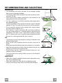
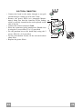
RECOMMENDATIONS AND SUGGESTIONS
INSTALLATION
• The manufacturer will not be held liable for any damages resulting
from incorrect or improper installation.
• The minimum safety distance between the cooker top and the extrac-
tor hood is 650 mm.
• Check that the mains voltage corresponds to that indicated on the
rating plate fixed to the inside of the hood.
• For Class I appliances, check that the domestic power supply guaran-
tees adequate earthing.
Connect the extractor to the exhaust flue through a pipe of minimum
diameter 120 mm. The route of the flue must be as short as possible.
• Do not connect the extractor hood to exhaust ducts carrying combus-
tion fumes (boilers, fireplaces, etc.).
• If the extractor is used in conjunction with non-electrical appliances
(e.g. gas burning appliances), a sufficient degree of aeration must be
guaranteed in the room in order to prevent the backflow of exhaust
gas. The kitchen must have an opening communicating directly with
the open air in order to guarantee the entry of clean air.
USE
• The extractor hood has been designed exclusively for domestic use to
eliminate kitchen smells.
• Never use the hood for purposes other than for which it has ben de-
signed.
• Never leave high naked flames under the hood when it is in operation.
• Adjust the flame intensity to direct it onto the bottom of the pan only,
making sure that it does not engulf the sides.
• Deep fat fryers must be continuously monitored during use: over-
heated oil can burst into flames.
• The hood should not be used by children or persons not instructed in
its correct use.
MAINTENANCE
• Switch off or unplug the appliance from the mains supply before carry-
ing out any maintenance work.
• Clean and/or replace the Filters after the specified time period.
• Clean the hood using a damp cloth and a neutral liquid detergent.
650 mm min.

EN
1
9
19
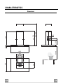
CHARACTERISTICS
Dimensions
650 min.
676
60
898
max. 940
min. 740
740
290
350
150
90
315
135
ø

EN
2
0
20
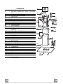
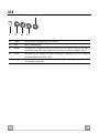
Components
Ref. Q.ty Product Components
1 1 Hood Body, complete with: Controls, Light, Blower,
Filters
2 1 Telescopic Chimney comprising:
2.1 1 Upper Section
2.2 1 Lower Section
7.1 1 Telescopic frame complete with extractor, consisting of:
7.1a 1 Upper frame
7.1b 1 Lower frame
8a 1 Right Air Outlet Grill
8b 1 Left Air Outlet Grill
9 1 Reducer Flange ø 150-120 mm
14 1 Hood Body Air Outlet Extension Piece consisting of two
Half Shells
14.1 1 Air Outlet Connection Extension
15 1 Air Outlet Connection
24 1 Junction box
25 2 Pipe clamps
Ref. Q.ty Installation Components
11 4 Wall Plugs ø 10
12c 6 Screws 2,9 x 6,5
12e 2 Screws 2,9 x 9,5
12f 4 Screws M6 x 10
12g 4 Screws M6 x 80
12h 4 Screws 5,2 x 70
21 1 Drilling template
22 4 6.4 mm int. dia washers
23 4 M6 nuts
Q.ty Documentation
1 Instruction Manual
12c
7.1a
7.1
22
23
12h
7.1b
2
2.1
2.2
8b
8a
12c
11
21
12g
1
12f
24
12e
14.1
15
14
12c
25
9

EN
2
1
21
INSTALLATION
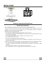
Drilling the Ceiling/shelf and fixing the frame
DRILLING THE CEILING/SHELF
• Use a plumb line to mark the centre of the hob on the ceiling/support shelf.
• Place the drilling template 21 provided on the ceiling/support shelf, making sure that the
template is in the correct position by lining up the axes of the template with those of the hob.
• Mark the centres of the holes in the template.
• Drill the holes at the points marked:
• For concrete ceilings, drill for plugs appropriate to the screw size.
• For hollow brick ceilings with wall thickness of 20 mm: drill ø 10 mm(immediately insert
the Dowels 11 supplied).
• For wooden beam ceilings, drill according to the wood screws used.
• For wooden shelf, drill ø 7 mm.
• For the power supply cable feed, drill ø 10 mm.
• For the air outlet (Ducted Version), drill according to the diameter of the external air ex-
haust duct connection.
• Insert two screws of the following type, crossing them and leaving 4-5 mm from the ceiling:
• For concrete ceilings, use the appropriate plugs for the screw size (not provided).
• for Cavity ceiling with inner space, with wall thickness of approx. 20 mm, Screws 12h,
supplied.
• For wooden beam ceilings, use 4 wood screws (not provided).
• For wooden shelf, use 4 screws 12g with washers 22 and nuts 23, provided.

EN
2
2
22
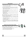
FIXING THE frame
• Loosen the two screws fastening the lower chimney and re-
move this from the lower frame.
• Loosen the two screws fastening the upper chimney and re-
move this from the upper frame.
If you wish to adjust the height of the frame, proceed as follows:
• Unfasten the eight metric screws joining the two columns, lo-
cated at the sides of the frame.
• Adjust the frame to the height required, then replace all the
screws removed as above.
• Insert the upper chimney stack from above, and leave it run-
ning free on the frame.
• Lift up the frame, fit the frame slots onto the screws up to the
slot end positions.
• Tighten the two screws and fasten the other two screws pro-
vided with the hood.
Before tightening the screws completely it is possible to adjust
the frame by turning it. Make sure that the screws do not come
out of their seats in the slotted holes.
• The frame mountings must be secure to withstand the weight
of the hood and any stresses caused by the occasional side
thrust applied to the device.
On completion, check that the base is stable, even if the frame
is subjected to bending.
• In all cases where the ceiling is not strong enough at the sus-
pension point, the installer must provide strengthening using
suitable plates and backing pieces anchored to the structurally
sound parts.
2
2
1
1
Ducted version air exhaust system Connection
When installing the ducted version, connect the hood to the
chimney using either a flexible or rigid pipe ø 150 or 120 mm,
the choice of which is left to the installer.
• To install a ø 120 mm air exhaust connection, insert the re-
ducer flange 9 on the hood body outlet.
• Fix the pipe using the pipe clamps 25 provided.
• Remove any activated charcoal filters.
9
ø 150
ø 120
25
25

EN
2
3
23
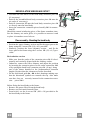
RECIRCULATION VERSION AIR OUTLET
• Assemble the two halves of the hood body extension piece 14
(if necessary).
• Push fit the assembled hood body extension piece 14 onto the
air outlet (if necessary).
• Push fit connection 15 onto the hood body extension piece 14
or directly onto the hood body.
• Insert the connection extension pieces laterally 14.1 in connec-
tion 15.
Should the central reinforcing piece of the frame somehow inter-
fere the chimney air outlet grille, it is possible to unscrew it and
to place it in another screw hole set.
14
15
14.1
Flue assembly - Mounting the hood body
• Position the upper chimney section and fix the upper part to the
frame using the 2 screws 12c (2,9 x 6,5) provided.
• Similarly, position the lower chimney section and fix the
lower part to the frame using the 2 screws 12c (2,9 x 6,5) pro-
vided.
Recirculation version
• Make sure that the outlet of the extension pieces 14.1 is hori-
zontally and vertically aligned with the chimney outlets.
• Otherwise, remove the lower chimney and adjust the position
by inverting the extension pieces for air outlet connection 14.1
or by cutting the hood body extension piece 14 (if any) along
one of the chases destined to the predetermined extension
lengths. Replace then the elements as earlier described.
• Fit the directional grids 8a - 8b in their housings making sure
that the directional symbols are towards the top. Also make
sure that they are correctly inserted in the connection exten-
sion pieces 14.1.
Before fixing the hood body to the frame:
• Remove the grease filters from the hood body.
• Remove any activated charcoal filters.
• From below, use the 4 screws 12f (M6 x 10 )provided to fix
the hood body to the frame.
12f
8b
8a
12c
12c

EN
2
4
24
ELECTRICAL CONNECTION
• Connect the hood to the mains through a two-pole
switch having a contact gap of at least 3 mm.
• Remove the grease filters (see paragraph Mainte-
nance) being sure that the connector of the feeding
cable is correctly inserted in the socket placed on the
side of the fan.
• Connect the control connector Cmd.
• Place the connectors in the junction box 24 and close
it using the 2 screws 12e (2,9 x 9,5) provided.
• Fix the junction box to the hood body using the 2
screws 12c (2,9 x 6,5) provided.
• For the recirculation version, fit the activated carbon
odour filter.
• Replace the grease filters.
24
12e
Cmd
12c

EN
2
5
25
USE
L
V1 V2 V3
S
L Light Switches the lighting system on and off.
S Led Motor running led.
V1 Motor Switches the extractor motor on and off at low speed. Used to provide a
contin-uos and silent air change in the presence of light cooking vapours.
V2 Speed Medium speed, suitable for most operating conditions given the optimum
treated air flox/noise level ratio.
V3 Intensive Maximum speed, used for eliminating the highest cooking vapour emission,
including long periods.

EN
2
6
26
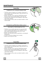
MAINTENANCE
Grease filters
CLEANING METAL SELF- SUPPORTING GREASE FILTERS
• The filters must be cleaned every 2 months of operation, or
more frequently for particularly heavy usage, and can be wa-
shed in a dishwasher.
• Remove the filters one at a time by pushing them towards
the back of the group and pulling down at the same time.
• Wash the filters, taking care not to bend them. Allow them
to dry before refitting.
• When refitting the filters, make sure that the handle is visible
on the outside.
Activated charcoal filter (Recirculation version)
REPLACING THE ACTIVATED CHARCOAL FILTER
• The filter is not washable and cannot be regenerated, and
must be replaced approximately every 4 months of opera-
tion, or more frequently for particularly heavy usage.
• Remove the metal grease filters
• Remove the saturated activated carbon filter by releasing the
fixing hooks
• Fit the new filter by hooking it into its seating
• Replace the metal grease filters.
Grease filters
CLEANING METAL SELF- SUPPORTING GREASE FILTERS
• The filters must be cleaned every 2 months of operation, or
more frequently for particularly heavy usage, and can be wa-
shed in a dishwasher.
• Remove the filters one at a time by pushing them towards
the back of the group and pulling down at the same time.
• Wash the filters, taking care not to bend them. Allow them
to dry before refitting.
• When refitting the filters, make sure that the handle is visible
on the outside.

4329694_ver4
Il simbolo sul prodotto o sulla confezione indica che il prodotto non deve essere considerato come un normale rifiuto domestico, ma deve essere portato nel
punto di raccolta appropriato per il riciclaggio di apparecchiature elettriche ed elettroniche. Provvedendo a smaltire questo prodotto in modo appropriato, si contribuisce
a evitare potenziali conseguenze negative per lambiente e per la salute, che potrebbero derivare da uno smaltimento inadeguato del prodotto. Per informazioni
più dettagliate sul riciclaggio di questo prodotto, contattare lufficio comunale, il servizio locale di smaltimento rifiuti o il negozio in cui è stato acquistato il prodotto.
The symbol on the product or on its packaging indicates that this product may not be treated as household waste. Instead it shall be handed over to the applicable
collection point for the recycling of electrical and electronic equipment. By ensuring this product is disposed of correctly, you will help prevent potential negative
consequences for the environment and human health, which could otherwise be caused by inappropriate waste handling of this product. For more detailed information
about recycling of this product, please contact your local city office, your household waste disposal service or the shop where you purchased the product.
Le symbole sur le produit ou son emballage indique que ce produit ne peut être traité comme déchet ménager. Il doit plutôt être remis au point de ramassage
concerné, se chargeant du recyclage du matériel électrique et électronique. En vous assurant que ce produit est éliminé correctement, vous favorisez la prévention
des conséquences négatives pour lenvironnement et la santé humaine qui, sinon, seraient le résultat dun traitement inapproprié des déchets de ce produit. Pour
obtenir plus de détails sur le recyclage de ce produit, veuillez prendre contact avec le bureau municipal de votre région, votre service délimination des déchets
ménagers ou le magasin où vous avez acheté le produit.
Das Symbol auf dem Produkt oder seiner Verpackung weist darauf hin, dass dieses Produkt nicht als normaler Haushaltsabfall zu behandeln ist, sondern an
einem Sammelpunkt für das Recycling von elektrischen und elektronischen Geräten abgegeben werden muss. Durch Ihren Beitrag zum korrekten Entsorgen dieses
Produkts schützen Sie die Umwelt und die Gesundheit Ihrer Mitmenschen. Umwelt und Gesundheit werden durch falsches Entsorgen gefährdet. Weitere Informationen
über das Recycling dieses Produkts erhalten Sie von Ihrem Rathaus, Ihrer Müllabfuhr oder dem Geschäft, in dem Sie das Produkt gekauft haben.
Het symbool op het product of op de verpakking wijst erop dat dit product niet als huishoudafval mag worden behandeld. Het moet echter naar een plaats
worden gebracht waar elektrische en elektronische apparatuur wordt gerecycled. Als u ervoor zorgt dat dit product op de correcte manier wordt verwijderd, voorkomt
u mogelijk voor mens en milieu negatieve gevolgen die zich zouden kunnen voordoen in geval van verkeerde afvalbehandeling. Voor meer details in verband met
het recyclen van dit product, neemt u het best contact op met de gemeentelijke instanties, het bedrijf of de dienst belast met de verwijdering van huishoudafval of
de winkel waar u het product hebt gekocht.
El símbolo en el producto o en su embalaje indica que este producto no se puede tratar como desperdicios normales del hogar. Este producto se debe entregar
al punto de recolección de equipos eléctricos y electrónicos para reciclaje. Al asegurarse de que este producto se deseche correctamente, usted ayudará a evitar
posibles consecuencias negativas para el ambiente y la salud pública, lo cual podría ocurrir si este producto no se manipula de forma adecuada. Para obtener
información más detallada sobre el reciclaje de este producto, póngase en contacto con la administración de su ciudad, con su servicio de desechos del hogar o
con la tienda donde compró el producto.
O símbolo no produto ou na embalagem indica que este produto não pode ser tratado como lixo doméstico. Em vez disso, deve ser entregue ao centro de
recolha selectiva para a reciclagem de equipamento eléctrico e electrónico. Ao garantir uma eliminação adequada deste produto, irá ajudar a evitar eventuais
consequências negativas para o meio ambiente e para a saúde pública, que, de outra forma, poderiam ser provocadas por um tratamento incorrecto do produto.
Para obter informações mais pormenorizadas sobre a reciclagem deste produto, contacte os serviços municipalizados locais, o centro de recolha selectiva da sua
área de residência ou o estabelecimento onde adquiriu o produto.
Dir. 89/336/CEE
73/23/CEE
93/68/CEE
-
 1
1
-
 2
2
-
 3
3
-
 4
4
-
 5
5
-
 6
6
-
 7
7
-
 8
8
-
 9
9
-
 10
10
-
 11
11
-
 12
12
-
 13
13
-
 14
14
-
 15
15
-
 16
16
-
 17
17
-
 18
18


Zanussi ZHC941X Manuale utente
- Categoria
- Cappe da cucina
- Tipo
- Manuale utente
in altre lingue
- English: Zanussi ZHC941X User manual
Altri documenti
-
Juno-Electrolux JDI5571E Manuale utente
-
 Franke Consumer Products FDF 9044 I Manuale utente
-
 Franke Consumer Products FGC 906 I Manuale utente
-
-
-
AEG DI7490-M Manuale utente
-
Franke FDB 10078 I Instructions for Use and Installation
-
 Franke Consumer Products FDMO 607 I Manuale utente
-
Electrolux EFA9150X Manuale utente
-


