Ubiquiti UAP-AC-PRO Guida Rapida
- Categoria
- Punti di accesso WLAN
- Tipo
- Guida Rapida

Access Point Ubiquiti UniFi
Indoor UAP-AC-PRO
O UniFi é o revolucionário sistema Wi-Fi que combina
desempenho empresarial, escalabilidade ilimitada e um
controlador de gerenciamento central.
O Access Point possui a mais recente tecnologia Wi-Fi
802.11ac, 3x3 MIMO em um design industrial refinado e é
ideal para a implantação de redes sem fio de desempenho
máximo.
www.bztech.com.br

802.11ac Dual-Radio
Pro Access Point
Model: UAP-AC-PRO

Introduction
Thank you for purchasing the Ubiquiti Networks®
UniFi®802.11ac Dual-Radio Pro Access Point. This Quick Start
Guide is designed to guide you through installation and
includes warranty terms.
IMPORTANT: The UAP-AC-PRO requires the UniFi
Controller v5.4 or higher, available at:
www.ubnt.com/download/unifi
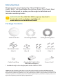
Package Contents
UniFi AP AC Pro Mounting Bracket Ceiling Backing Plate
Flat Head Screws
(Qty. 4)
Keps Nuts
(Qty. 4)
Screws
(Qty. 4)
Screw Anchors
(Qty. 4)
Cable Feed Plug Gigabit PoE* (48V, 0.5A)
with Mount Bracket
Power Cord*
* Included only in the single-pack of the UAP-AC-PRO
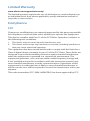
TERMS OF USE: Ubiquiti radio devices must be professionally installed. Shielded Ethernet
cable and earth grounding must be used as conditions of product warranty. TOUGHCable
™
is
designed for outdoor installations. It is the professional installer’s responsibility to follow local
country regulations, including operation within legal frequency channels, output power, and
Dynamic Frequency Selection (DFS) requirements.

Installation Requirements
• Phillips screwdriver
• Drill and drill bit (6 mm for wall-mounting or 3 mm for
ceiling-mounting)
• Optional: Drywall or keyhole saw (to cut 18 mm hole for
Ethernet cable feed)
• Cat5/6 UTP cable for indoor installations
Outdoor Installation Requirements
IMPORTANT: The UAP-AC-PRO may be installed
outdoors under an eave or other protected location. Do
not install the UniFi AP in an open environment.
• Mounting location should be at least 60 cm (2 ft) from the
edge of the eave or ceiling.
• Cable feed opening must be directed away from the open
environment.
• Cable feed must be pointed downwards when wall-mounted.
• Shielded Category 5 (or above) cabling with drain wire
should be used for all outdoor wired Ethernet connections
and should be grounded through the AC ground of the PoE.
We recommend that you protect your networks from
harmful outdoor environments and destructive ESD events
with industrial-grade, shielded Ethernet cable from Ubiquiti
Networks. For more details, visit
www.ubnt.com/toughcable
System Requirements
• Linux, MacOSX, or Microsoft Windows 7/8/10
• Java Runtime Environment 1.8 or above recommended
• Web Browser: Google Chrome (Other browsers may have
limited functionality.)
• UniFi Controller software v5.4 or newer (available at:
www.ubnt.com/download/unifi)

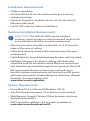
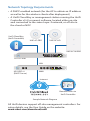
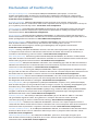
Network Topology Requirements
• A DHCP-enabled network (for the AP to obtain an IP address
as well as for the wireless clients after deployment)
• A UniFi Cloud Key or management station running the UniFi
Controller v5.4 (or newer) software, located either on-site
and connected to the same Layer-2 network, or off-site in
the cloud or NOC
US-16-150W
USG-PRO-4
(DHCP Server)
Internet
UAP-AC-PRO
UAP-AC-M-PRO
UAP-AC-HD
LAN
WAN
UniFi Cloud Key
(UniFi Controller)
Remote Access too
UniFi Controllerr
Good
Fair
Poor
Great
Network:
Switches
12
Gateway
ধ£-A!ধ32
18%
Internet
Capacity
43%
Clients
412
Guests
113
IoT
45
Everything is
great
My Dashboard
Edit Widgets
-24hrs
-24hrs
Max
980
-2
0
Now
Now
Throughput
Latency
ISP Load:
Great
-24hrs
Max
0
Now
-8ধ1'
-24hrs
High
Low
Now
Retry Rate
Great
Wi-Fi Load:
225.2 Mbps
125.2 Mbps
1
-f-8!ă$-9;8-#<ধ32
36
6
11
40
44
48
52
56
60
64
100
104
108
112
116
120
124
128
132
136
140
149
153
157
161
165
A
WA
Access Points
20
39;$ধ='9
ă$'
Back Room
Storage
Roof
!££>!@'WWW
91 GB
86 GB
53 GB
48 GB
45 GB
3666£-$!ধ329
YouTube
£-'2;9
29;!+8!1
£-'2;9
Squarespace
£-'2;9
33+£'
£-'2;9
Facebook
£-'2;9
Top Interference
ă$'
Roof
Storage
51%
45%
45%
Top CPU Usage
ă$'
Back Room
Home
51%
45%
45%
39;$ধ='£-'2;9
Wi-Fi Key Metrics
£-'2;9
-,32'
¥£-'2;9
2&83-&
£-'2;9
MacBook
£-'2;9
PC Laptop
£-'2;9
iPad
39;$ধ='>-;$,'9
36'138@9!+'
£-'2;8'7<'2$@-9;8-#<ধ32
'=-$'-9;8-#<ধ32
SW-24A
f-;$,'2
SW-8A
f32('8'2$'
SW-8B
Storage
SW-24E
Roof
SW-24D
!££>!@'WWW
56.9%
56.9%
35.6%
35.6%
34%
34%
28%
28%
24%
24%
32+'9;£-'2;6ধ1'
-f-<11!8@
3<ধ2+ধ£-A!ধ32
>-;$,<11!8@
iPad-1
692£-2'
!;'>!@f!-2
32;83££'8fă$'
32;83££'8fă$'
¦ধ£-A!ধ32
¦ধ£-A!ধ32
¦ধ£-A!ধ32
2£-2'
MBP-2
£-'2;9
iPad-2
ধ£-A!ধ32
£-'2;9
38;ধ£-A!ধ32
8d 4h 0m
32
24
2d 8h 30m
1,324
2d 8h 30m
64%
1,324
32%
Port Usage
!1'
Status
Users
Guests
Purpose
='8!+'!;!
Port 1- GB
VPN-LA-PDX
21
2
Corporate
320 GB
Port 2 - GB PoE+
VPN-LA-PDX2
6
0
2£@
11 GB
Port 3- 10 GB
'13;'fø$'f
43
0
2£@
12 GB
120
80
32
f32('8'2$'
45%
ă$'f8;'6;
45%
MBP-1
8!ă$
Devices
8!ă$
2d 8h 30m
248 GB
536
1,248 GB
Port 4- GB POE
8!29('8f
7
12
2£@
0 GB
13
0%
0%
0%
100%
100%
100%
Average Capacity
500 Mbps
='8!+'-8ধ1'ধ£-A!ধ32
8%
='8!+'6'$;8!£ă$-'2$@
Wl#c9mA
1300 Mbps
0 Mbps
100%
0%
l#c9mA
W¤l#c9mA
2;'82';322'$ধ32V
30 Mbps
40 Mbps
50 Mbps
20 Mbps
10 Mbps
0 Mbps
-24 hrs
-12 hrs
Now
3>2£3!&
,'38'ধ$!£!6!$-;@
Throughput
Portlan
d
SDN
Last 24 Hrs
A
64% 11ac W2
08% 11n
13 LAN
01 LAN
50%
03 WLAN
28% 11ac
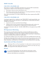
Sample Network Diagram
All UniFi devices support off-site management controllers. For
setup details, see the User Guide on the website:
www.ubnt.com/download/unifi

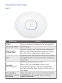
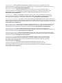
Hardware Overview
LED
LED Color Status
White Factory default, waiting to be integrated.
Flashing White Initializing.
Alternating
White/Blue
Device is busy; do not touch or unplug it.
This usually indicates that a process such
as a firmware upgrade is taking place.
Blue
Indicates the device has been successfully
integrated into a network and is working
properly.
Quickly
Flashing Blue
This is used to locate an AP.
When you click Locate in the UniFi
Controller software, the AP will flash. It
will also display the location of the AP on
the map.
Steady Blue
with Occasional
Flashing
Indicates the device is in an isolated state
(all WLANs are brought down until an
uplink is found).

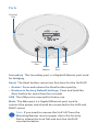
Ports
Main
Port
Secondary
Port
Security
Slot
Reset
Button
USB
Port
Secondary The Secondary port is a Gigabit Ethernet port used
for bridging.
Reset The Reset button serves two functions for the UniFi AP:
• Restart Press and release the Reset button quickly.
• Restore to Factory Default Settings Press and hold the
Reset button for more than five seconds.
USB The USB port is reserved for future use.
Main The Main port is a Gigabit Ethernet port used to
connect the power and should be connected to the LAN and
DHCPserver.
Note: If you need to remove the UniFi AP from the
Mounting Bracket, insert a paper clip in the Security
Slot to release the Lock Tab and turn the UniFi AP
counterclockwise.

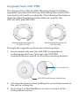
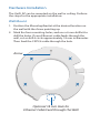
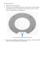
Upgrade from UAP-PRO
The design of the UAP-AC-PRO Mounting Bracket facilitates
upgrades from the UAP-PRO, by eliminating the need to drill
new holes in the wall or ceiling tile. The following illustrations
show the Mounting Bracket holes that are used for the
UAP-AC-PRO and UAP-PRO:
Mounting Bracket Holes (4)
for UAP-AC-PRO
Mounting Bracket Holes (3)
for UAP-PRO
To begin the upgrade, perform the following steps:
1. Insert a paper clip into the UAP-PRO Locking Notch
to disengage the lock. Then turn the UAP-PRO
counterclockwise and lift it off of the mounting bracket.
Locking Notch
UAP-PRO (wall mount installation)
2. Unscrew the three screws holding the mounting bracket to
the wall or ceiling tile.
3. Go to step 3 of the Wall Mount section or step 4 of the
Ceiling Mount section.

Hardware Installation
The UniFi AP can be mounted on the wall or ceiling. Perform
the steps for the appropriate installation:
Wall Mount
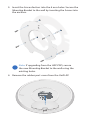
1. Position the Mounting Bracket at the desired location on
the wall with the Arrow pointing up.
2. Mark the four mounting holes, and use a 6 mm drill bit to
drill the holes. If your Ethernet cable feeds through the
wall, cut or drill a circle approximately 18 mm in diameter.
Then feed the CAT5/6 cable through the hole.
Optional 18 mm Hole for
Ethernet Cable Feed through the Wall
Arrow

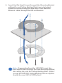
3. Insert the Screw Anchors into the 6 mm holes. Secure the
Mounting Bracket to the wall by inserting the Screws into
the anchors.
Note: If upgrading from the UAP-PRO, secure
the new Mounting Bracket to the wall using the
existingholes.
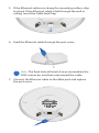
4. Remove the rubber port cover from the UniFi AP.

5. If the Ethernet cable runs along the mounting surface, skip
to step 6. If the Ethernet cable is fed through the wall or
ceiling, insert the Cable Feed Plug.
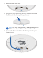
6. Feed the Ethernet cable through the port cover.
Note: The feed hole will stretch to accommodate the
RJ45 connector, and then seal around the cable.
7. Connect the Ethernet cable to the Main port and replace
the port cover.

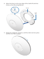
8. Align the Notch on the top edge of the UniFi AP with the
Arrow on the Mounting Bracket.
Lock
Tab
Arrow
Notch
9. Rotate the UniFi AP clockwise until the tabs lock into place
and the Lock Tab engages.

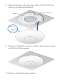
Ceiling Mount
1. Remove the ceiling tile.
2. Place the Ceiling Backing Plate in the center of the ceiling
tile. Mark the four mounting screw holes and an 18 mm
hole for the Ethernet cable feed.
18 mm Hole for Ethernet Cable Feed
3. Use a 3 mm drill bit to drill the screw holes, and cut or drill
the hole for the Ethernet cable feed.

4. Insert the Flat Head Screws through the Mounting Bracket,
ceiling tile, and Ceiling Backing Plate (see note below).
Fasten the screws using the Keps Nuts. Then feed the
Ethernet cable through the tile and bracket.
Note: If upgrading from the UAP-PRO, insert the
Flat Head Screws through the new Mounting Bracket,
the ceiling tile, and the Ceiling Backing Plate. (Either
re-use the UAP-PRO Ceiling Backing Plate or replace
it with the new UAP-AC-PRO plate.)

5. Insert the Cable Feed Plug.
6. Remove the port cover from the UniFi AP, and then feed
the Ethernet cable through the port cover.
Note: The feed hole will stretch to accommodate the
RJ45 connector, and then seal around the cable.
7. Connect the Ethernet cable to the Main port and replace
the port cover.

8. Align the Notch on the top edge of the UniFi AP with the
Arrow on the Mounting Bracket.
Lock Tab
Arrow
Notch
9. Rotate the UniFi AP clockwise until the tabs lock into place
and the Lock Tab engages.
10. Set the ceiling tile back into place.

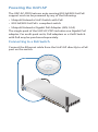
Powering the UniFi AP
The UAP-AC-PRO features auto-sensing 802.3af/802.3at PoE
support and can be powered by any of the following:
• Ubiquiti Networks UniFi Switch with PoE
• 802.3af/802.3at PoE+ compliant switch
• Ubiquiti Networks Gigabit PoE Adapter (48V, 0.5A)
The single-pack of the UAP-AC-PRO includes one Gigabit PoE
adapter. For multi-pack units, PoE adapters or a UniFi Switch
with PoE may be purchased separately.
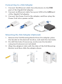
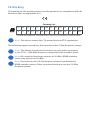
Connecting to a PoE Switch
Connect the Ethernet cable from the UniFiAP directly to a PoE
port on the switch.
1 3 5 7 9 11 13 15 17 19 21 22
2 4 6 8 10 12 14 16 18 20 22 24
SFP1
SFP2

Connecting to a PoE Adapter
1. Connect the Ethernet cable from the device to the POE
port of the Gigabit PoE adapter.
2. Connect an Ethernet cable from your LAN to the LAN port
of the Gigabit PoE adapter.
3. Connect the Power Cord to the adapter, and then plug the
Power Cord into a power outlet.
Mounting the PoE Adapter (Optional)
1. Remove the PoE Mounting Bracket from the adapter, place
the bracket at the desired location, and mark the two holes.
2. Pre-drill the holes if necessary, and secure the bracket
using two fasteners (not included).
3. Align the adapter’s slots with the tabs of the PoE Mounting
Bracket, and then slide the adapterdown.

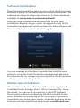
Software Installation
Download and install the latest version of the UniFi Controller
software. Launch it and follow the on-screen instructions. The
software and step-by-step instructions in the User Guide are
available at: www.ubnt.com/download/unifi
After you have installed the software and run the UniFi
Installation Wizard, a login screen will appear for the UniFi
Controller management interface. Enter the Admin Name and
Password that you created and click Log In.
You can manage your wireless network and view network
statistics using the UniFi Controller management interface.
For information on configuring and using the UniFi Controller
software, refer to the User Guide.
Mobile App Installation
Ubiquiti Networks also offers the UniFi mobile app, which
is available from the App Store® (iOS) or Google Play
™
Store
(Android). You can use it to provision a UniFi AP for basic
functionality without configuring a UniFi Controller. It also
allows seamless provisioning of APs for remote controllers
(controllers not on the same Layer 2 network) and easy access
to local controllers and those monitored on unifi.ubnt.com

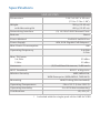
Specifications
UAP-AC-PRO
Dimensions 196.7 x196.7 x 35 mm
(7.74 x 7.74 x 1.38")
Weight
with Mounting Kit
350 g (12.35 oz)
450 g (15.87 oz)
Networking Interface (2) 10/100/1000 Ethernet Ports
Buttons Reset
Power Method PoE 802.3af/802.3at
Power Supply 48V, 0.5A Gigabit PoE Adapter*
Max. Power Consumption 9W
Operating Frequency 2.4 GHz
5 GHz
Max. TX Power
2.4 GHz
5 GHz
22 dBm
22 dBm
Antennas (3) Dual-Band Antennas, 3 dBi each
Wi-Fi Standards 802.11 a/b/g/n/ac
Wireless Security WEP, WPA-PSK,
WPA-Enterprise (WPA/WPA2, TKIP/AES)
Mounting Wall/Ceiling (Kits Included)
Operating Temperature -10 to 70° C (14 to 158° F)
Operating Humidity 5 to 95% Noncondensing
Certications CE, FCC, IC
* Included with the single-pack of the UAP-AC-PRO
La pagina si sta caricando...
La pagina si sta caricando...
La pagina si sta caricando...
La pagina si sta caricando...
La pagina si sta caricando...
La pagina si sta caricando...
La pagina si sta caricando...
La pagina si sta caricando...
La pagina si sta caricando...
-
 1
1
-
 2
2
-
 3
3
-
 4
4
-
 5
5
-
 6
6
-
 7
7
-
 8
8
-
 9
9
-
 10
10
-
 11
11
-
 12
12
-
 13
13
-
 14
14
-
 15
15
-
 16
16
-
 17
17
-
 18
18
-
 19
19
-
 20
20
-
 21
21
-
 22
22
-
 23
23
-
 24
24
-
 25
25
-
 26
26
-
 27
27
-
 28
28
-
 29
29


Ubiquiti UAP-AC-PRO Guida Rapida
- Categoria
- Punti di accesso WLAN
- Tipo
- Guida Rapida
in altre lingue
Documenti correlati
-
Ubiquiti Networks UniFi UAP-AC-LITE Manuale utente
-
Ubiquiti UniFI UAP-AC Guida Rapida
-
-
Ubiquiti UAP-nanoHD Compact 802.11ac Wave 2 Enterprise Access Point Guida utente
-
-
Ubiquiti UAP-PRO Guida Rapida
-
-
-
-