AKG PT 40 Manuale del proprietario
- Categoria
- Microfoni
- Tipo
- Manuale del proprietario

PT 40
bodypack transmitter
Bedienungshinweise . . . . . . . . . . . . . . . . . . S. 2
Bitte vor Inbetriebnahme des Gerätes lesen!
User Instructions . . . . . . . . . . . . . . . . . . . . p. 10
Please read the manual before using the equipment!
Mode d’emploi . . . . . . . . . . . . . . . . . . . . . . p. 18
Veuillez lire cette notice avant d’utiliser le système!
Istruzioni per l’uso . . . . . . . . . . . . . . . . . . . p. 26
Prima di utilizzare l’apparecchio, leggere il manuale!
Modo de empleo . . . . . . . . . . . . . . . . . . . . p. 34
Antes de utilizar el equipo, sírvase leer el manual!
Instruções de uso . . . . . . . . . . . . . . . . . . . p. 42
Favor leia este manual antes de usar o equipamen
to!
WMS40
wireless microphone system

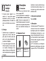
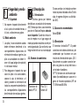
1 Sicherheit und
Umwelt
1.1 Sicherheit
1. Setzen Sie das Gerät nicht direkter
Sonneneinstrahlung, starker Staub-
und Feuchtigkeitseinwirkung, Regen,
Vibrationen oder Schlägen aus.
1.2 Umwelt
1. Entsorgen Sie verbrauchte Batterien
und Akkus immer gemäß den jeweils
geltenden Entsorgungsvorschriften.
Werfen Sie Batterien oder Akkus
weder ins Feuer (Explosionsgefahr)
noch in den Restmüll.
2. Wenn Sie das Gerät verschrotten, ent-
fernen Sie die Batterien bzw. Akkus,
trennen Sie Gehäuse, Elektronik und
Kabel und entsorgen Sie alle
Komponenten gemäß den dafür gelten-
den Entsorgungsvorschriften.
2 Beschreibung
2.1 Einleitung
Vielen Dank, dass Sie sich für ein
Produkt aus dem Hause AKG entschie-
den haben. Bitte lesen Sie die
Bedienungsanleitung aufmerksam
durch, bevor Sie das Gerät benützen,
und bewahren Sie die Bedienungs-
anleitung sorgfältig auf, damit Sie jeder-
zeit nachschlagen können. Wir wün-
schen Ihnen viel Spaß und Erfolg!
2.2 Lieferumfang
Kontrollieren Sie bitte, ob die Ver-
packung alle oben angeführten Teile ent-
hält. Falls etwas fehlt, wenden Sie sich
bitte an Ihren AKG-Händler.
2.3 Empfohlenes Zubehör
Tasche CB 40
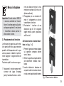
2.4 Beschreibung
An den Taschensender PT 40 können
Sie sowohl dynamische Mikrofone als
auch Kondensatormikrofone an-
schließen, die mit einer Versorgungs-
spannung von ca. 3,8 Volt arbeiten.
Selbstverständlich können Sie auch eine
E-Gitarre, einen E-Bass oder ein
Umhängekeyboard anschließen.
Der PT 40 arbeitet auf einer fixen, quarz-
stabilisierten Trägerfrequenz im UHF-
Trägerfrequenzbereich von 710 MHz bis
865 MHz.
2
1 Taschensender
PT 40
2 Batterien 1,5 V,
Größe AA

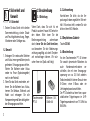
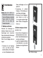
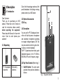
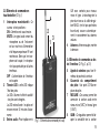
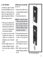
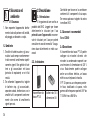
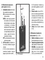
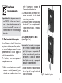
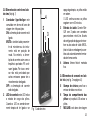
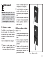
2.5 Bedienelemente an der
Oberseite (siehe Abb. 1)
1 Ein/Ausschalter: Dieser Schiebe-
schalter hat drei Stellungen:
ON: Die Spannungsversorgung für
den Sender ist eingeschaltet.
MUTE: Das vom Mikrofon bzw.
Instrument kommende Audio-
signal ist stummgeschaltet,
Spannungsversorgung und HF-
Trägerfrequenz bleiben jedoch
eingeschaltet. Dadurch wird der
Empfänger trotz ”abgeschalte-
tem Mikrofon nicht durch andere
Sender gestört.
OFF: Die Spannungsversorgung für
den Sender ist ausgeschaltet.
2 Kontroll-LED: Diese LED zeigt den
Ladezustand der Batterien an.
LED leuchtet beim Einschalten kurz
auf und erlischt wieder: Batterien in
Ordnung.
LED leuchtet: Batterien in ca. 50
Minuten erschöpft.
3 Audioeingang: 3-polige Mini-XLR-
Buchse mit Kontakten für Mikrofon-
und Linepegel. Durch die Stecker-
beschaltung der empfohlenen
AKG-Mikrofone bzw. des Gitarren-
kabels MKG/L (nicht mitgeliefert)
werden automatisch die richtigen
Kontakte belegt.
4 Antenne: Fix montierte, flexible
Antenne.
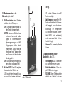
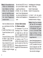
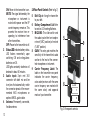
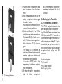
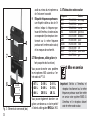
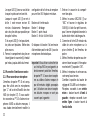
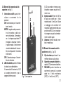
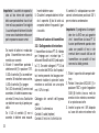
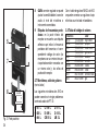
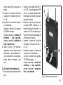
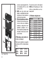
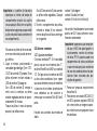
2.6 Bedienelemente an der
Rückseite (s. Abb. 2, S. 4)
5 Gürtelspange: Zum Befestigen
des Taschensenders am Gürtel.
6 Batteriefachdeckel: Siehe Ka-
pitel 3.2 Batterien einlegen.
7 MIC/LINE: Dieser Schiebeschalter
schaltet den Audioteil zwischen
3
Abb. 1: Oberseite
1
2
3
4

Mikrofonpegel (”MIC”) und Line-
pegel (”LINE”) um.
8 GAIN: Mit diesem Regler können
Sie die Empfindlichkeit des
Audioteils an den Pegel des ange-
schlossenen Mikrofons bzw.
Instruments anpassen.
9Trägerfrequenzetikette: An der
Rückseite des Senders ist eine
Haftetikette mit der Trägerfrequenz
des Senders, dem entsprechenden
Farbcode (Empfänger mit dersel-
ben Trägerfrequenz sind mit dersel-
ben Farbe gekennzeichnet) und den
Prüfzeichen angebracht.
2.7 Mikrofone, Gitarrenkabel (nicht
mitgeliefert)
Folgende AKG-Mikrofone können Sie
problemlos an den Audioeingang des
PT 40 anschließen:
Mittels des Gitarrenkabels MKG/L von
AKG können Sie eine E-Gitarre, einen E-
Bass oder ein Umhängekeyboard an-
schließen.
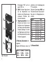
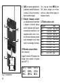
2.8 Farbcode-Tabelle
4
7
5
6
8
9
2 x 1.5V
+–
+
–
Abb. 2: Rückseite
C 417 L
C 420 L
C 444 L
C 419 L
D 409 L
CK 55 L
C 411 L
C 418 L
LM 3 L
Frequenz Farbe
US54: 710.400 MHz rotbraun
US58: 734.600 MHz purpur
KR3: 745.650 MHz mintgrün
KR4: 750.900 MHz dunkelgrau
EU62: 802.525 MHz bordeauxrot
EU63: 812.800 MHz gelb
UK69A: 854.900 MHz violett
UK69B: 858.200 MHz grün
ISM1: 863.100 MHz melonengelb
ISM2: 864.375 MHz grau

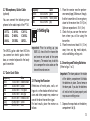
3 Inbetriebnahme
3.1 Empfänger positionieren
Reflexionen des Sendersignals an
Metallteilen, Wänden, Decken, etc. oder
Abschattungen durch menschliche
Körper können das direkte Sendersignal
schwächen bzw. auslöschen.
Stellen Sie den Empfänger daher wie
folgt auf:
1. Positionieren Sie den Empfänger
immer in der Nähe des Aktions-
bereiches (Bühne), achten Sie jedoch
auf einen Mindestabstand zwischen
Sender und Empfänger von 3 m bis
optimal 5 m.
2. Voraussetzung für optimalen
Empfang ist Sichtverbindung zwi-
schen Sender und Empfänger.
3. Positionieren Sie den Empfänger in
einem Abstand von mehr als
1,5 m von großen metallenen Gegen-
stände, Wänden, Bühnengerüsten,
Decken, u.ä.
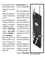
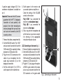
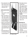
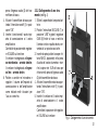
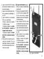
3.2 Batterien einlegen und testen
(siehe Abb. 1 bis 3)
1. Drücken Sie den Schnapphaken am
Batteriefachdeckel (6) nach unten.
2. Ziehen Sie den Batteriefachdeckel (6)
nach unten vom Sender ab.
3. Legen Sie die mitgelieferten Batterien
in das Batteriefach ein und achten
Sie dabei auf die richtige Polarität der
Batterien.
5
Wichtig: Bevor Sie Ihr WMS 40 in
Betrieb nehmen, kontrollieren Sie, ob
Sender und Empfänger auf derselben
Frequenz arbeiten. Am leichtesten
können Sie dies anhand des
Farbcodes überprüfen.
Abb. 3: Batterien einlegen

Wenn Sie die Batterien falsch einle-
gen, wird der Sender nicht mit Strom
versorgt.
4. Schalten Sie den Sender ein, indem
Sie den Ein/Aus-Schalter (1) auf “ON”
stellen.
Die Kontroll-LED (2) blitzt kurz auf. Wenn
die Batterien in gutem Zustand sind,
erlischt die Kontroll-LED (2 )wieder.
Wenn die Kontroll-LED (2) zu leuch-
ten beginnt, sind die Batterien in ca.
50 Minuten erschöpft. Tauschen Sie
die Batterien möglichst bald gegen
frische aus.
Wenn die Kontroll-LED (2) nicht auf-
blitzt, sind die Batterien erschöpft.
Legen Sie neue Batterien ein.
5. Schließen Sie das Batteriefach,
indem Sie den Batteriefachdeckel
von unten auf das Batteriefach auf-
schieben, bis der Schnapphaken ein-
rastet.
3.3 Sender in Betrieb nehmen
3.3.1 Mikrofon anschließen
Der Taschensender PT 40 ist für die
Verwendung mit den ”L”-Mikrofonen
der MicroMic-Serie von AKG (siehe
Kapitel 2.7) ausgelegt. Wenn Sie andere
Mikrofone von AKG oder auch von ande-
ren Herstellern an den PT 40 an-
schließen möchten, beachten Sie bitte,
dass Sie eventuell den Stecker Ihres
Mikrofons umlöten oder durch einen 3-
poligen Mini-XLR-Stecker ersetzen müs-
sen.
Kontaktbelegung des Audioeingangs:
Kontakt 1: Abschirmung
Kontakt 2: Tonader (inphase)
Kontakt 3: Versorgungsspannung
An Kontakt 3 steht eine positive
Versorgungsspannung von 3,8 V für
Kondensatormikrofone zur Verfügung.
1. Nehmen Sie den Batteriefachdeckel ab.
2. Stellen Sie den MIC/LINE-Schalter (7)
auf ”MIC” und drehen Sie mit einem
kleinen Schraubenzieher den GAIN-
Regler (8) bis zur Mitte zwischen dem
linken und rechten Anschlag auf.
6
Wichtig: Der Schaumstoffpolster an der
Innenseite des Batteriefachdeckels
fixiert die Batterien in ihrer Position.
Entfernen Sie den Schaumstoff-
polster nicht, da die Batterien anson-
sten nicht richtig im Batteriefach
fixiert sindund Klappergeräusche
verursachen können
Wichtig: Wir bitten Sie um Verständnis
dafür, dass AKG eine einwandfreie
Funktion des Taschensenders PT 40
mit Fremdfabrikaten nicht garantie-
ren kann, und eventuelle Schäden
infolge des Betriebs mit Fremd-
fabrikaten von der Garantieleistung
ausgeschlossen sind.

3. Stecken Sie den Mini-XLR-Stecker am
Kabel Ihres Mikrofons an die Audio-
Eingangsbuchse (3) des Taschen-
senders an.
4. Schalten Sie den Taschensender ein,
indem Sie den Ein/Aus-Schalter auf
”ON” stellen.
5. Schalten Sie den Empfänger und Ihre
PA-Anlage bzw. Ihren Verstärker ein.
Kontrollieren Sie die Stellung des
VOLUME-Reglers am Empfänger:
Empfänger mit Mikrofoneingang
verbunden = linker Anschlag,
Empfänger mit Line-Eingang ver-
bunden = rechter Anschlag.
6. Sprechen oder singen Sie in das
Mikrofon und stellen Sie die Laut-
stärke der PA-Anlage bzw. des
Verstärkers wie in deren Bedienungs-
anleitung beschrieben oder nach
Gehör ein. (Siehe auch Kapitel 4
Mikrofontechnik.)
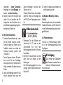
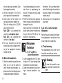
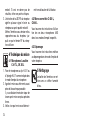
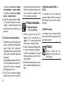
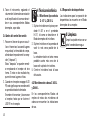
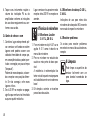
3.3.2 Instrument anschließen (s. Abb. 4)
1. Nehmen Sie den Batteriefachdeckel
ab.
2. Stellen Sie den MIC/LINE-Schalter (7)
auf ”LINE” und drehen Sie mit einem
kleinen Schraubenzieher den GAIN-
Regler (8) bis zur Mitte zwischen dem
linken und rechten Anschlag auf.
3. Stecken Sie den Klinkenstecker des
Gitarrenkabels MKG/L (optional) an
die Ausgangsbuchse Ihres Instru-
ments und den Mini-XLR-Stecker
des Gitarrenkabels an die Audio-
Eingangsbuchse (3) des Taschen-
senders an.
4. Schalten Sie den Taschensender ein,
indem Sie den Ein/Aus-Schalter auf
”ON” stellen.
5. Schalten Sie den Empfänger und Ihre
PA-Anlage bzw. Ihren Verstärker ein.
Kontrollieren Sie die Stellung des
VOLUME-Reglers am Empfänger:
Empfänger mit Mikrofoneingang
7
3
7
8
Abb. 4: Instrument anschließen

verbunden = linker Anschlag,
Empfänger mit Line-Eingang ver-
bunden = rechter Anschlag.
6. Spielen Sie auf Ihrem Instrument und
stellen Sie die Lautstärke der PA-
Anlage bzw. des Verstärkers wie in
deren Bedienungsanleitung beschrie-
ben oder nach Gehör ein.
3.4 Vor dem Soundcheck
1. Schreiten Sie den Bereich ab, in dem
Sie den Sender einsetzen werden.
Achten Sie dabei auf Stellen, wo die
Feldstärke absinkt und daher der
Empfang kurzzeitig gestört wird
(“Dropouts”).
Solche Dropouts können Sie behe-
ben, indem Sie den Empfänger
anders positionieren. Hat dies keinen
Erfolg, vermeiden Sie diese kritischen
Stellen.
2. Wenn am Empfänger die die RF-LED
erlischt, bedeutet dies, dass kein
Signal empfangen wird oder der
Squelch aktiv ist.
Schalten Sie den Sender ein und/oder
gehen Sie näher zum Empfänger, bis
die RF-LED am Empfänger aufleuch-
tet.
4 Mikrofontechnik
4.1 Lavaliermikrofone
C 417 L, CK 55 L
1. Befestigen Sie das Mikrofon am
Ansteckclip H 40/1 oder an der
Anstecknadel H 41/1 wie in der
Bedienungsanleitung des Mikofons
beschrieben.
2. Klemmen Sie das Mikrofon so nahe
beim Mund wie möglich an der
Kleidung an.
Die Rückkopplungsgefahr ist umso
geringer, je näher das Mikrofon beim
Mund sitzt!
3. Achten Sie darauf, das Mikrofon auf
den Mund auszurichten.
4.2 Headset-Mikrofone C 420 L,
C 444 L
Anwendungshinweise für diese beiden
Headset-Mikrofone von AKG finden Sie
in der Bedienungsanleitung des jeweili-
gen Mikrofons.
4.3 Fehlerbehebung
Hinweise zur Fehlerbehebung finden
Sie in der Bedienungsanleitung Ihres
Empfängers.
5 Reinigung
Zum Reinigen der Oberflächen
des Senders verwenden Sie am
besten ein mit Wasser befeuchte-
tes weiches Tuch.
8

9
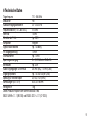
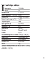
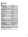
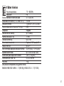
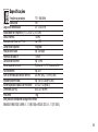
6 Technische Daten
Trägerfrequenz 710 - 865 MHz
Modulation FM
Audioübertragungsbandbreite 40 - 20.000 Hz
Frequenzstabilität (-10°C bis +50°C) ±15 kHz
Nennhub 15 kHz
Klirrfaktor bei 1 kHz typ. 0,8%
Kompander integriert
Signal/Rauschabstand typ. 103 dB(A)
HF-Ausgangsleistung 10 mW
Stromaufnahme typ. 70 mA
Spannungsversorgung 2 x 1,5 V-Batterien Größe AA
Betriebszeit typ. 30 h
Audio-Eingangspegel für Nennhub 300 mV (MIC); 110 mV (LINE)
Eingangsimpedanz typ. 140 kΩ//450 pF (LINE)
Speisung für Mikrofonkapsel 3,8 V/4,7 kΩ (Stift 3)
Abmessungen (B x T x H) 64 x 22 x 96 mm
Nettogewicht 76 g
Dieses Produkt entspricht den Normen EN60065:1998,
EN301 489-9 v.1.1.1 (09-2000) und EN300 422-2 v.1.1.1 (07-2000).

FCC Statement
This equipment has been tested and
found to comply with the limits for a Class
B digital device, pursuant to Parts 74, 15,
and 90 of the FCC Rules. These limits are
designed to provide reasonable protec-
tion against harmful interference in a resi-
dential installation. This equipment gene-
rates, uses, and can radiate radio fre-
quency energy and, if not installed and
used in accordance with the instructions,
may cause harmful interference to radio
communications. However, there is no
guarantee that interference will not occur
in a particular installation. If this equip-
ment does cause harmful interference to
radio or television reception, which can
be determined by turning the equipment
off and on, the user is encouraged to try
to correct the interference by one or more
of the following measures:
• Reorient or relocate the receiving
antenna.
• Increase the separation between the
equipment and the receiver.
• Connect the equipment into an outlet
on a circuit different from that to
which the receiver is connected.
• Consult the dealer or an experienced
radio/TV technician for help.
Shielded cables and I/O cords must be
used for this equipment to comply with
the relevant FCC regulations.
Changes or modifications not expressly
approved in writing by AKG Acoustics
may void the user’s authority to operate
this equipment.
This device complies with Part 15 of the
FCC Rules. Operation is subject to the
following two conditions: (1) this device
may not cause harmful interference, and
(2) this device must accept any inter-
ference received, including interference
that may cause undesired operation.
1 Safety and
Environment
1.1 Safety
1. Do not expose the equipment to
direct sunlight, excessive dust, moi-
sture, rain, mechanical vibrations, or
shock.
1.2 Environment
1. Be sure to dispose of used batteries
as required by local waste disposal
rules. Never throw batteries into a fire
(risk of explosion) or garbage bin.
2. When scrapping the equipment,
remove the batteries, separate the
case, circuit boards, and cables, and
dispose of all components in accord-
ance with local waste disposal rules.
10

2 Description
2.1 Introduction
Dear Customer:
Thank you for purchasing an AKG
product. Please take a few minutes to
read the instructions below carefully
before operating the equipment.
Please keep the Manual for future refe-
rence. Have fun and impress your
audience!
2.2 Unpacking
Check that the package contains all the
parts listed above. If anything is missing,
please contact your AKG dealer.
2.3 Optional Accessories
CB 40 bag
2.4 Description
You can use the PT 40 bodypack trans-
mitter with both dynamic microphones
and condenser microphones operating
on a supply voltage of approx. 3.8 V. You
may also connect an electric guitar, elec-
tric bass, or remote keyboard.
The PT 40 operates on one fixed, quartz
stabilized frequency in the 710 MHz to
865 MHz UHF carrier frequency range.
2.5 Top Panel Controls (Refer to fig. 1)
1On/Off Switch: This slide switch
provides three positions labeled as
follows:
11
Fig. 1: Top panel controls
1
2
3
4
1 PT 40 bodypack
transmitter
2 AA size dry
batteries

ON: Power to the transmitter is on.
MUTE: The signal delivered by the
microphone or instrument is
muted while power and the RF
carrier frequency remain on. This
prevents the receiver from re-
sponding to interference from
other transmitters.
OFF: Power to the transmitter is off.
2 Status LED: Indicates battery status.
LED flashes momentarily upon
switching ON and extinguishes:
batteries are OK.
LED lights constantly: batteries will
be dead in about 50 minutes.
3 Audio input: 3-pin mini XLR
connector with both mic and line
level pins that automatically match
the connector pinout of the recom-
mended AKG microphones or
optional MKG/L guitar cable.
4Antenna: Permanently connected,
flexible antenna.
2.6 Rear Panel Controls (Refer to fig. 2)
5 Belt Clip for fixing the transmitter
to your belt.
6 Battery Compartment Lid: Refer
to section 3.2 Inserting Batteries.
7 MIC/LINE: This slide switch sets
the audio input either to micropho-
ne level (“MIC” position) or line level
(“LINE” position).
8 GAIN: This rotary pot matches the
sensitivity of the transmitter’s audio
section to the level of the connec-
ted microphone or instrument.
9 Carrier Frequency Label: The
label on the transmitter rear panel
indicates the carrier frequency,
color code (receivers with the same
carrier frequency are marked with
the same color), and approval
marks of your transmitter.
12
7
5
6
8
9
2 x 1.5V
+–
+
–
Fig. 2: Rear panel controls

2.7 Microphones, Guitar Cable
(optional)
You can connect the following micro-
phones to the audio input of the PT 40:
The MKG/L guitar cable from AKG lets
you connect an electric guitar, electric
bass, or remote keyboard to the body-
pack transmitter.
2.7 Color Code Table
3 Setting Up
3.1 Placing the Receiver
Reflections off metal parts, walls, cei-
lings, etc. or the shadow effects of musi-
cians and other people may weaken or
cancel the direct transmitter signal.
For best results, place the receiver as
follows:
1. Place the receiver near the perform-
ance area (stage). Make sure, though,
that the transmitter will never get any
closer to the receiver than 10 ft (3 m).
Optimum separation is 16 ft. (5 m).
2. Check that you can see the receiver
from where you will be using the
transmitter.
3. Place the receiver at least 5 ft. (1.5 m)
away from any big metal objects,
walls, scaffolding, ceilings, etc.
3.2 Inserting and Testing Batteries
(Refer to figs. 1 to 3)
1. Depress the snap hook on the battery
compartment lid (6).
13
Frequency Color
US54: 710.400 MHz reddish brown
US58: 734.600 MHz purple
KR3: 745.650 MHz mint green
KR4: 750.900 MHz dark gray
EU62: 802.525 MHz Bordeaux red
EU63: 812.800 MHz yellow
UK69A: 854.900 MHz violet
Frequency Color
UK69B: 858.200 MHz green
ISM1: 863.100 MHz melon yellow
ISM2: 864.375 MHz gray
Important: Prior to setting up your
WMS 40, check that the transmitter
and receiver are tuned to the same
frequency. The easiest way to do this
is to compare the color codes on the
transmitter and receiver.
Important: The foam pads on the inside
of the battery compartment lid holds
the batteries in place. Do not remove
the foam pad. If you do, the batteries
will not be held in place properly and
may cause a rattling noise.
C 417 L
C 420 L
C 444 L
C 419 L
D 409 L
CK 55 L
C 411 L
C 418 L
LM 3 L

2. Pull the battery compartment lid (6)
down to remove it from the trans-
mitter.
3. Insert the supplied batteries into the
battery compartment conforming to
the polarity marks.
The transmitter will not function with
incorrectly inserted batteries.
4. Set the on/off switch (1) to “ON” to
switch the power to the transmitter on.
The status LED (2) will flash momen-
tarily. If the batteries are in good con-
dition, the status LED (2) will extin-
guish.
If the status LED (2) illuminates the
batteries will be dead within about 50
minutes. Replace the batteries with
new ones as soon as possible.
If the status LED (2) fails to flash
momentarily the batteries are dead.
Insert new batteries.
5. To close the battery compartment,
slide the battery compartment
lid (6) onto the battery compartment
from below to the point that it will
click shut.
3.3 Setting Up the Transmitter
3.3.1 Connecting a Microphone
The PT 40 bodypack transmitter has
been designed primarily for use with ”L”
type MicroMic Series microphones from
AKG (see section 2.7). If you wish to
connect other microphones from AKG or
other manufacturers to the PT 40, plea-
se note that you may have to rewire the
existing connector of your microphone
or replace it with a 3-pin mini XLR
connector.
Audio input pinout:
Pin 1: shield
Pin 2: audio (inphase)
Pin 3: supply voltage
14
Fig. 3: Inserting batteries

A positive supply voltage of 3.8 V for
condenser microphones is available on
pin 3.
1. Remove the battery compartment lid.
2. Set the MIC/LINE switch (7) to “MIC”
and use a small screwdriver to set the
GAIN control (8) to a position halfway
between full CCW and full CW.
3. Plug the mini XLR connector on the
cable of your microphone into the
audio input connector (3) on the
bodypack transmitter.
4. Set the on/off switch (1) to “ON” to
switch power to the transmitter on.
5. Switch power to the receiver and
your sound system or amplifier on.
Check the setting of the VOLUME
control on the receiver:
Fully CCW if you connected the
receiver to a microphone input.
Fully CW if you connected the
receiver to a line input.
6. Talk or sing into the microphone and
set the levels on your mixer or ampli-
fier referring to the appropriate
instruction manual or by ear.
3.3.2 Connecting an Instrument (fig. 4)
1. Remove the battery compartment lid.
2. Set the MIC/LINE switch (7) to “LINE”
and use a small screwdriver to set the
GAIN control (8) to a position halfway
between full CCW and full CW.
3. Plug the 1/4” jack plug on the option-
al MKG/L guitar cable to the output
jack on your instrument and the mini
XLR connector on the guitar cable
15
Important: Please note that AKG cannot
guarantee that the PT 40 bodypack
transmitter will work perfectly with
products from other manufacturers
and any damage that may result from
such use is not covered by the AKG
warranty scheme.
3
7
8
Fig. 4: Connecting an instrument

into the audio input connector (3) on
the bodypack transmitter.
4. Set the on/off switch (1) to “ON” to
switch power to the transmitter on.
5. Switch power to the receiver and
your sound system or amplifier on.
Check the setting of the VOLUME
control on the receiver:
Fully CCW if you connected the
receiver to a microphone input.
Fully CW if you connected the
receiver to a line input.
6. Play your instrument and set the
levels on your mixer or amplifier refer-
ring to the appropriate instruction
manual or by ear.
3.4 Before the Soundcheck
1. Move the transmitter around the area
where you will use the system to
check the area for "dead spots", i.e.,
places where the field strength seems
to drop and reception deteriorates.
If you find any dead spots, try to elim-
inate them by repositioning the
receiver. If this does not help, avoid
the dead spots.
2. The RF LED on the receiver going out
means no signal is being received or
the squelch is active.
Switch power to the transmitter ON
and/or move closer to the receiver, to
the point that the RF LED on the
receiver will come back on.
4 Microphone
Technique
4.1 C 417 L, CK 55 L
Lavalier Microphones
1. Fix the microphone to the H 40/1 lava-
lier clip or H 41/1 tie pin referring to the
microphone’s instruction manual.
2. Clamp the microphone on your cloth-
ing as close as possible to your
mouth.
Remember that gain-before-feed-
back will be the higher the smaller the
distance between the microphone
and the mouth!
3. Make sure to aim the microphone at
your mouth.
4.2 C 420 L, C 444 L Head-worn
Microphones
Refer to the user’s manual of the respec-
tive microphone for instructions on how
to use head-worn microphones.
4.3 Troubleshooting
For troubleshooting hints, refer to the
instruction manual of your receiver.
5 Cleaning
To clean the transmitter case,
use a soft cloth moistened with
water.
16

17
6 Specifications
Carrier frequency range 710 to 865 MHz
Modulation FM
Audio bandwidth 40 to 20,000 Hz
Frequency stability (-10°C to +50°C) ±15 kHz
Rated deviation 15 kHz (SP1, SP2: 13.5 kHz)
T.H.D. at 1 kHz 0.8% typ.
Compander integrated
Signal/noise ratio 103 dB(A) typ.
RF output 10 mW
Current consumption 70 mA typ.
Power requirement two 1.5-V AA size batteries
Battery life 30 hours typ.
Audio input level for rated deviation 300 mV (MIC); 110 mV (LINE)
Input impedance typ. 140 kΩ//450 pF (LINE)
Condenser mic power supply 3.8 V/4.7 kΩ (pin 3)
Size (WxDxH) 64 x 22 x 96 mm / (2.5 x 0.9 x 3.8 in.)
Net weight 76 g (2.7 oz.)
This product complies with the following standards:
EN60065:1998, EN301 489-9 v.1.1.1 (09-2000), and EN300 422-2 v.1.1.1 (07-2000).

1 Sécurité et
écologie
1.1. Sécurité
1. Ne placez jamais l’appareil à un
endroit où il risque d’être exposé
directement au soleil, à une atmos-
phère poussiéreuse, à l’humidité, à la
pluie, aux vibrations ou aux secous-
ses.
1.2. Ecologie
1. Conformez-vous aux règlements en
vigueur pour la mise au rebut des
piles usées. Ne mettez jamais des
piles ni au feu (risque d’explosion) ni
aux ordures ménagères.
2. Si vous mettez l'appareil à la ferraille,
enlevez les piles ou les accus, sépa-
rez le boîtier, l'électronique et les
câbles et éliminez les différents élé-
ments conformément aux règlements
en vigueur.
2 Description
2.1 Introduction
Nous vous remercions d’avoir
choisi un produit AKG.
Lisez très attentivement ce mode d’em-
ploi avant la mise en service de l’ap-
pareil. Conservez soigneusement le
mode d’emploi pour pouvoir le consulter
lorsque vous vous posez des questions.
Nous vous souhaitons beaucoup de
succès.
2.2. Equipement fourni
Contrôlez si le carton contient bien tous
les éléments énumérés ci-dessus. Si ce
n’est pas le cas, veuillez contacter votre
distributeur AKG.
2.3 Accessoires optionnels
Pochette CB 40
2.4 Description
L’émetteur de poche PT 40 peut être uti-
lisé aussi bien avec des microphones
dynamiques qu’avec des microphones
électrostatiques fonctionnant sur une
tension d’alimentation de 3,8 volts envi-
ron. Vous avez bien sûr aussi la possibi-
lité de raccorder une guitare, une basse
ou un clavier portatif.
Le PT 40 fonctionne sur une fréquence
porteuse fixe, stabilisée par cristal, dans
la gamme UHF de 710 MHz à 865 MHz.
18
1 émetteur de
poche PT 40
2 piles de 1,5 V,
dimension AA

2.5 Eléments de commande en
haut de boîtier
(Cf. Fig. 1)
1 Interrupteur marche/arrêt : Ce
curseur a trois positions :
ON : L’émetteur est sous tension.
MUTE : Le signal audio venant du
microphone ou de l’instrument
est sur muet mais l’alimentation
et la fréquence porteuse HF sont
maintenues. Bien que le micro-
phone soit coupé, le récepteur
n’est pas perturbé par d’autres
émetteurs.
OFF : L’alimentation de l’émetteur
est coupée.
2 Témoin LED : cette LED indique
l’état des piles.
La LED s’allume et s’éteint aussitôt
: les piles sont chargées.
La LED reste allumée : les piles ont
encore environ 50 minutes d’auto-
nomie.
3 Entrée audio : Prise tripôlaire mini
XLR avec contacts pour niveaux
micro et ligne. Le brochage de la
prise du micro ou du câble de gui-
tare MKG/L (ne fait pas partie des
fournitures) assure automatique-
ment le raccordement aux bornes
voulues.
4 Antenne : Antenne souple, montée
à demeure.
2.6 Eléments de commande au dos
de l’émetteur (Cf. Fig. 2, p. 20)
5 Agrafe de ceinture : pour fixer l’é-
metteur de poche à la ceinture
6 Couvercle du compartiment
des piles : Voir point 3.2 Mise en
place des piles
7 MIC/LINE : Ce curseur permet de
commuter la section audio entre
niveau micro (“MIC”) et niveau ligne
(“LINE”).
8 GAIN : Ce régulateur permet d’ad-
apter la sensibilité de la section
19
Fig. 1 : Eléments de commande (en haut)
1
2
3
4

audio au niveau du microphone ou
de l’instrument raccordé.
9 Etiquette fréquences porteuses :
une étiquette collée au dos de l’é-
metteur indique la fréquence por-
teuse de l’émetteur, le code couleur
correspondant (les récepteurs fonc-
tionnant sur la même fréquence
porteuse ont le même code couleur)
et les marques de conformité.
2.7 Microphones, câble guitare (ne
font pas partie des fournitures)
Vous pouvez brancher sans problème
les microphones AKG suivants sur l’en-
trée audio du PT 40:
Vous pouvez également brancher une
guitare, une basse ou un clavier portatif
à l’aide du câble guitare MKG/L d’AKG.
2.8 Tableau des codes couleur
3 Mise en service
20
7
5
6
8
9
2 x 1.5V
+–
+
–
Fig. 2 : Eléments de commande (dos)
Fréquence Couleur
US54: 710.400 MHz brun rouge
US58: 734.600 MHz pourpre
KR3: 745.650 MHz menthe
KR4: 750.900 MHz gris foncé
EU62: 802.525 MHz bordeaux
EU63: 812.800 MHz jaune
UK69A: 854.900 MHz violet
UK69B: 858.200 MHz vert
ISM1: 863.100 MHz jaune melon
ISM2: 864.375 MHz gris
Important: Vérifiez si l’émetteur et
récepteur fonctionnent sur la même
fréquence porteuse avant de mettre
en service votre système WMS 40.
L’émetteur et le récepteur doivent
avoir le même code couleur.
C 417 L
C 420 L
C 444 L
C 419 L
D 409 L
CK 55 L
C 411 L
C 418 L
LM 3 L
La pagina si sta caricando...
La pagina si sta caricando...
La pagina si sta caricando...
La pagina si sta caricando...
La pagina si sta caricando...
La pagina si sta caricando...
La pagina si sta caricando...
La pagina si sta caricando...
La pagina si sta caricando...
La pagina si sta caricando...
La pagina si sta caricando...
La pagina si sta caricando...
La pagina si sta caricando...
La pagina si sta caricando...
La pagina si sta caricando...
La pagina si sta caricando...
La pagina si sta caricando...
La pagina si sta caricando...
La pagina si sta caricando...
La pagina si sta caricando...
La pagina si sta caricando...
La pagina si sta caricando...
La pagina si sta caricando...
La pagina si sta caricando...
La pagina si sta caricando...
La pagina si sta caricando...
La pagina si sta caricando...
La pagina si sta caricando...
La pagina si sta caricando...
La pagina si sta caricando...
La pagina si sta caricando...
La pagina si sta caricando...
La pagina si sta caricando...
La pagina si sta caricando...
La pagina si sta caricando...
La pagina si sta caricando...
-
 1
1
-
 2
2
-
 3
3
-
 4
4
-
 5
5
-
 6
6
-
 7
7
-
 8
8
-
 9
9
-
 10
10
-
 11
11
-
 12
12
-
 13
13
-
 14
14
-
 15
15
-
 16
16
-
 17
17
-
 18
18
-
 19
19
-
 20
20
-
 21
21
-
 22
22
-
 23
23
-
 24
24
-
 25
25
-
 26
26
-
 27
27
-
 28
28
-
 29
29
-
 30
30
-
 31
31
-
 32
32
-
 33
33
-
 34
34
-
 35
35
-
 36
36
-
 37
37
-
 38
38
-
 39
39
-
 40
40
-
 41
41
-
 42
42
-
 43
43
-
 44
44
-
 45
45
-
 46
46
-
 47
47
-
 48
48
-
 49
49
-
 50
50
-
 51
51
-
 52
52
-
 53
53
-
 54
54
-
 55
55
-
 56
56


AKG PT 40 Manuale del proprietario
- Categoria
- Microfoni
- Tipo
- Manuale del proprietario
in altre lingue
- English: AKG PT 40 Owner's manual
- français: AKG PT 40 Le manuel du propriétaire
- español: AKG PT 40 El manual del propietario
- Deutsch: AKG PT 40 Bedienungsanleitung
- português: AKG PT 40 Manual do proprietário