
Agilent Technologies
Operation and Maintenance
Manual
Agilent 355 Sulfur and 255 Nitrogen
Chemiluminescence Detectors

Notices
© Agilent Technologies, Inc. 2007
No part of this manual may be reproduced
in any form or by any means (including
electronic storage and retrieval or transla-
tion into a foreign language) without prior
agreement and written consent from Agi-
lent Technologies, Inc. as governed by
United States and international copyright
laws.
Manual Part Number
G6600-90006
Edition
First edition, June 2007
Replaces G6600-90002
Printed in USA
Agilent Technologies, Inc.
2850 Centerville Road
Wilmington, DE 19808-1610 USA
Warranty
The material contained in this docu-
ment is provided “as is,” and is sub-
ject to being changed, without notice,
in future editions. Further, to the max-
imum extent permitted by applicable
law, Agilent disclaims all warranties,
either express or implied, with regard
to this manual and any information
contained herein, including but not
limited to the implied warranties of
merchantability and fitness for a par-
ticular purpose. Agilent shall not be
liable for errors or for incidental or
consequential damages in connection
with the furnishing, use, or perfor-
mance of this document or of any
information contained herein. Should
Agilent and the user have a separate
written agreement with warranty
terms covering the material in this
document that conflict with these
terms, the warranty terms in the sep-
arate agreement shall control.
Technology Licenses
The hardware and/or software described in
this document are furnished under a
license and may be used or copied only in
accordance with the terms of such license.
Restricted Rights Legend
If software is for use in the performance of
a U.S. Government prime contract or sub-
contract, Software is delivered and
licensed as “Commercial computer soft-
ware” as defined in DFAR 252.227-7014
(June 1995), or as a “commercial item” as
defined in FAR 2.101(a) or as “Restricted
computer software” as defined in FAR
52.227-19 (June 1987) or any equivalent
agency regulation or contract clause. Use,
duplication or disclosure of Software is
subject to Agilent Technologies’ standard
commercial license terms, and non-DOD
Departments and Agencies of the U.S. Gov-
ernment will receive no greater than
Restricted Rights as defined in FAR
52.227-19(c)(1-2) (June 1987). U.S. Govern-
ment users will receive no greater than
Limited Rights as defined in FAR 52.227-14
(June 1987) or DFAR 252.227-7015 (b)(2)
(November 1995), as applicable in any
technical data.
Safety Notices
CAUTION
A CAUTION notice denotes a haz-
ard. It calls attention to an operat-
ing procedure, practice, or the like
that, if not correctly performed or
adhered to, could result in damage
to the product or loss of important
data. Do not proceed beyond a
CAUTION notice until the indicated
conditions are fully understood and
met.
WARNING
A WARNING notice denotes a
hazard. It calls attention to an
operating procedure, practice, or
the like that, if not correctly per-
formed or adhered to, could result
in personal injury or death. Do not
proceed beyond a WARNING
notice until the indicated condi-
tions are fully understood and met.
Acknowledgements
Torx® is a registered trademark of Textron
Inc.; Teflon® is a registered trademark of
E.I. du Pont de Nemours and Company.
Kimwipe® is a registered trademark of the
Kimberly-Clark Corporation.

Operation and Maintenance Manual 3
Warnings
English
WARNING
This symbol on the instrument indicates that the user should refer to the man-
ual for operating instructions.
WARNING
Any operation requiring access to the inside of the equipment, could result in
injury. To avoid potentially dangerous shock, disconnect from power supply
before opening the equipment.
WARNING
For continued protection against fire hazard replace fuse with same type and
rating.
WARNING
This symbol indicates that to comply with European Union Directive
2002/96/EC for waste electrical and electronic equipment (WEEE), the Ana-
lyzer should be disposed of separately from standard waste.
WARNING
This is a safety Class I product. It must be wired to a mains supply with a protective
earthing ground incorporated into the power cord. Any interruption of the protective
conductor, inside or outside the equipment, is likely to make the instrument dangerous.
Intentional interruption is prohibited.
WARNING
If this instrument is used in a manner not specified by Agilent, the protection provided by
the instrument may be impaired.
WARNING
High voltage is present in the instrument when the power cord is connected, even if the
main power switch is in the standby mode. To avoid potentially dangerous shock, discon-
nect the power cord before removing the side panels.

4 Operation and Maintenance Manual
WARNING
Ozone is a hazardous gas and a strong oxidant. Exposure to ozone should be minimized
by using the instrument in a well-ventilated area and by venting the exhaust of the vac-
uum pump to a fume hood. The ozone generator should be turned off when the instrument
is not in use.
WARNING
Burner temperature Is extremely hot. Do not touch. Allow to cool before servicing.
WARNING
Hydrogen is an extremely flammable gas. Use appropriate care when handling. Inspect
all connections with a suitable leak detector.
WARNING
Oxygen rich environments can promote combustion and even result in spontaneous com-
bustion under conditions of high pressure and exposure to contamination. Use only oxy-
gen rated components and ensure that components are oxygen clean prior to use with
pure oxygen.
WARNING
Exceeding the gas inlet pressure of 25 psig (1.72 bar) may damage the hydrogen and oxi-
dant sensors or burst their connective tubing.

Operation and Maintenance Manual 5
Español
WARNING
Cualquier operación que requiera acceso al interior del equipo, puede causar
una lesión. Para evitar peligros potenciales, desconectarlo de la alimentación
a red antes de abrir el equipo.
WARNING
Para protección contínua contra el peligro de fuego, sustituir el fusible por
uno del mismo tipo y características.
WARNING
Este símbolo en el instrumento indica que el usuario debería referirse al man-
ual para instrucciones de funcionamiento.
WARNING
Esto es un producto con clase I de seguridad. Debe conectarse a una red que disponga de
tierra protectora en el cable de red. Cualquier interrupción del conductor protector,
dentro o fuera del equipo, puede ser peligroso. Se prohibe la interrupción intencionada.
WARNING
Si este instrumento se usa de una forma no especificada por Agilent, puede desactivarse
la protección suministrada por el instrumento.

6 Operation and Maintenance Manual
Français
WARNING
Chaque opération à l'intérieur de l'appareil, peut causer du préjudice. Afin
d'éviter un shock qui pourrait être dangereux, disconnectez l'appareil du
réseau avant de l'ouvrir.
WARNING
Afin de protéger l'appareil continuellement contre l'incendie, échangez le fus-
ible par un fusible du même type et valeur.
WARNING
Le symbol indique que l'utilisateur doit consulter le manuel d'instructions.
WARNING
Ceci est un produit de Classe de sécurité I. L'instrument doit être branché sur
l'alimentation secteur par un fil de secteur prévu d'une prise de masse. Chaque
interruption du conducteur protégeant, à l'intérieur ou á l'extérieur de l'appareil peut
rendre l'instrument dangereux. Interruption intentionnelle est interdite.
WARNING
Si l'instrument n'est pas utilisé suivant les instructions de Agilent, les dispositions de
sécurité de l'appareil ne sont plus valables.

Operation and Maintenance Manual 7
Deutsch
WARNING
Vor dem Öffnen des Gerätes Netzstecker ziehen!
WARNING
Für kontinuierlichen Schutz gegen Brandgefahr dürfen bei Sicherungswech-
sel nur Sicherungen der gleichen Stärke verwendet werden!
WARNING
Dieses Symbol auf dem Gerät weist darauf hin, dass der Anwender zuerst das
entsprechende Kapitel in der Bedienungsanleitung lesen sollte.
WARNING
Dies ist ein Gerät der Sicherheitsklasse I und darf nur mit einem Netzkabel mit
Schutzleiter betrieben werden. Jede Unterbrechung des Schutzleiters au erhalb oder
innerhalb des Gerätes kann das Gerät elektrisch gefährlich machen. Absichtliches
Unterbrechen des Schutzleiters ist ausdrücklich verboten.
WARNING
Wenn das Gerät nicht wie durch die Firma Agilent, vorgeschrieben und im Handbuch
beschrieben betrieben wird, können die im Gerät eingebauten Schutzvorrichtungen
beeinträchtigt werden.

8 Operation and Maintenance Manual
Italiano
WARNING
Qualsiasi intervento debba essere effettuato sullo strumento può essere
potenzialmente pericoloso a causa della corrente elettrica. Il cavo di alimen-
tazione deve essere staccato dallo strumento prima della sua apertura.
WARNING
Per la protezione da rischi da incendio in seguito a corto circuito, sostituire I
fusibili di protezione con quelli dello stesso tipo e caratteristiche.
WARNING
Il simbolo sullo strumento avverte l'utilizzatore di consultare il Manuale di
Istruzioni alla sezione specifica.
WARNING
Questo strumento è conforme alle specifiche per I prodotti in Classe I - Il cavo di
alimentazione dalla rete deve essere munito di "terra". Qualsiasi interruzione del cavo di
terra all'interno ed all'esterno dello strumento potrebbe risultare pericolòsa. Sono
proibite interruzioni intenzionali.
WARNING
Se questo strumento viene utilizzato in maniera non conforme alle specifiche di Agilent,
le protezioni di cui esso è dotato potrebbero essere alterate.

Operation and Maintenance Manual 9
Dutch
WARNING
Iedere handeling binnenin het toestel kan beschadiging veroorzaken. Om ied-
ere mogelijk gevaarlijke shock te vermijden moet de aansluiting met het net
verbroken worden, vóór het openen van het toestel.
WARNING
Voor een continue bescherming tegen brandgevaar, vervang de zekering door
een zekering van hetzelfde type en waarde.
WARNING
Het symbool geeft aan dat de gebruiker de instructies in de handleiding moet
raadplegen.
WARNING
Dit is een produkt van veiligheidsklasse I. Het toestel moet aangesloten worden op het
net via een geaard netsnoer. Bij onderbreking van de beschermende geleider, aan de
binnenzijde of aan de buitenzijde van het toestel, kan gebruik het toestel gevaarlijk
maken. Opzettelijke onderbreking is verboden.
WARNING
Indien het toestel niet gebruikt wordt volgens de richtlijnen van Agilent, gelden de
veiligheidsvoorzieningen niet meer.

10 Operation and Maintenance Manual
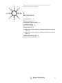
The following symbols are used on the equipment:
Caution - Refer to manual for
operating instructions
Caution - Risk of electrical
shock.
Caution - Hot surface.
Atención - Ver documentación
pertinente.
Atención - Riesgo de sacudidas
eléctricas.
Atención - Superficie caliente.
Attention - Consultez les
ocuments d'accomagnement.
Attention - Risque de choc
électrique.
Attention - Surface brûlante.
Vorsicht - Siehe beiliegende
Unterlagen.
Vorsicht - Risiko eines
Elektroschocks.
Vorsicht - Heisse Oberfläche.
Pericolo - Vedi
documentazione allegata.
Pericolo - Pericolo di scosse
elettriche.
Pericolo - Superficie rovente.
Voorzichtig - Raadpleeg di
bijehorende documentatie.
Voorzichtig - Hoge spanning,
levensgevaar.
Voorzichtig - Heet oppervlak.

Operation and Maintenance Manual 11
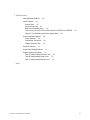
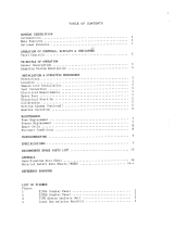
Contents
1 Introduction
2 System Description
Specifications 20
Technical Information — 355 SCD 20
Technical Information — 255 NCD 20
Physical Specifications 21
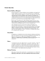
Theory of Operation 23
Sulfur Chemiluminescence Detector 23
Nitrogen Chemiluminescence Detector 23
Dual Plasma Controller 24
Description of Major Components 25
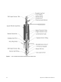
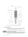
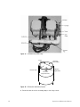
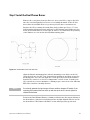
Dual Plasma Burner 25
Figure 1. Cross-Section of the Dual Plasma Burner for the 355 SCD 26
Figure 2. Cross-Section of the Dual Plasma Burner for the 255 NCD 27
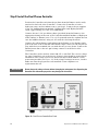
Dual Plasma Controller 27
Ozone Generator 28
Chemiluminescence Reaction Cell and Photomultiplier Tube 28
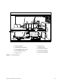
Figure 3. 355 SCD Left Side 29
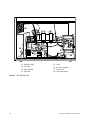
Figure 4. 355 SCD Right Side 30
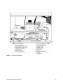
Figure 5. 255 NCD Left Side View 31
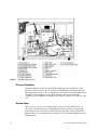
Figure 6. 255 NCD Right Side View 32
Pressure Transducer 32
Vacuum Pump 32
Chemical Trap 33
Oil Coalescing Filter 33
FID Adapter (Optional) 33
NCD Reaction Cell 33
NCD Photomultiplier Tube and Cooler 34
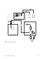
Figure 7. Schematic for 355 SCD 35
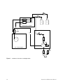
Figure 8. Schematic for 255 NCD, in Nitrogen Mode 36
Figure 9. Schematic for 255 NCD, in Nitrosamine Mode 37

12 Operation and Maintenance Manual
3 Installation
Overview 40
Step 1: Selecting a Location 41
Power Requirements 41
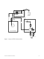
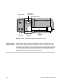
Figure 10. Drawing of the Detector with Dual Plasma Burner and Controller 42
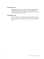
Environmental Considerations 42
Combustion Gas Requirements 42
Step 2: Unpack and Inspect the Instrument 45
Required Installation Tools 45
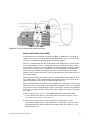
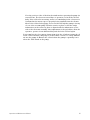
Step 3: Set Up the Vacuum Pump 46
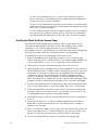
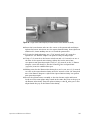
Installing the Edwards RV5 Pump Oil-Sealed Vacuum Pump 46
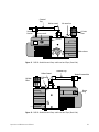
Figure 11. RV5 Oil-Sealed Vacuum Pump and Associated Traps (Front Side) 49
Figure 12. RV5 Oil-Sealed Vacuum Pump and Associated Traps (Back Side) 49
Figure 13. RV5 Oil- Sealed Vacuum Pump and Associated Traps (Top) 50
Figure 14. RV-5 Oil-S ealed Vacuum Pump Exhaust Line 51
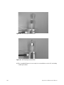
Installing the Welch Dry Piston Vacuum Pump 52
Figure 15. The Welch Dry Piston Pump 54
Figure 16. Oil Drain Kit with Ballast Control 54
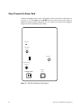
Step 4: Connect the Power Cord 56
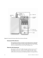
Figure 17. SCD Rear Panel Diagram 56
Step 5: Install the Dry Compressed Air or O
2
Supply 57
Step 6: Install the Signal Output Cables 58
Standard Cable Connection 58
HP 3390 Series Integrator Cable Connection 58
HP 3396 Integrator Cable Connection 58
HP 5890 GC Analog Input Board 58
Agilent 6890 GC Analog Input Board 58
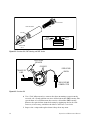
Step 7: Install the Dual Plasma Burner 59
Figure 18. Dimensions of GC Liner Cut-Outs 59
Step 8: Install the Dual Plasma Controller 60
Figure 19. Dual Plasma Controller Rear Panel 60
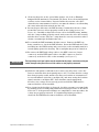
Step 9: Install Column Connections 61
Capillary Columns 61
Figure 20. Measuring Column Insertion 61

Operation and Maintenance Manual 13
Packed Columns and Columns with an Outside Diameter > 0.8 mm 61
Step 10: Install the Transfer Line 62
4 Front Panel Controls and Initial Startup
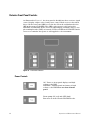
Detector Front Panel Controls 64
Figure 21. Front Panel Controls 64
Power Controls 64
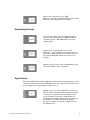
Display Output Controls 65
Signal Controls 65
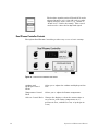
Dual Plasma Controller Controls 66
Figure 22. Dual Plasma Controller Front Panel 66
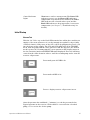
Initial Startup 67
Detector Interface Setup 69
Initial Checkout 69
Monitoring Oxidizer and Hydrogen Flow with the Dual Plasma Controller 70
5Operation
Start-Up Procedure 72
Detector Operation 73
Detector Stability and Response 73
Column Bleed 73
Coking 73
Hydrogen Poisoning 73
Contaminated Gases 74
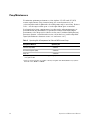
Fluctuating Pressures 74
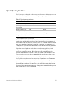
Typical Operating Conditions 75
Table 1. Typical Operating Conditions 75
Detection Limits 76
Table 2. Expected Detection Limits for Chromatographic Conditions 76
Instrument Shut-Down 77
Daily Shutdown 77
Complete Shutdown 77
Special Operating Modes 78
Using the 255 NCD in Nitrosamine Mode 78
Using the SCD in High Sensitivity Mode for Nonhydrocarbon Gaseous Samples 78

14 Operation and Maintenance Manual
6Maintenance
Pump Maintenance 82
Table 3. Operating Life of Components for Edwards RV5 Vacuum Pump 82
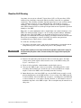
Cleaning the Detector 83
Changing the Oil Mist Filter (RV5) 84
Reaction Cell Cleaning 85
Figure 23. Reaction Cell, PMT Housing and PMT Socket 86
Figure 24. Reaction Cell 86
Flow Sensor Calibration 88
Detector Sensitivity 89
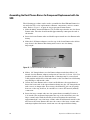
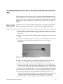
Assembling the Dual Plasma Burner for Component Replacement with the SCD 90
Figure 25. Ferrule Placement on Lower Burner Tube 90
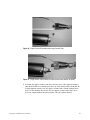
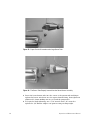
Figure 26. Proper Ferrule Orientation to the Large Ceramic Tube 91
Figure 27. Large Ceramic Tube Properly Inserted into the Quartz Heater Assembly 91
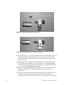
Figure 28. Orientation of the Double Taper Ferrule 92
Figure 29. Positioning the Upper Tube in the Union Fitting 92
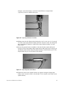
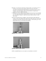
Figure 30. Tightening the Heater Swivel Nut 93
Figure 31. Proper Alignment of the Burner 93
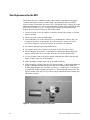
Assembling the Dual Plasma Burner for Component Replacement with the NCD 95
Figure 32. Ferrule Placement on Lower Burner Tube 95
Figure 33. Proper Ferrule Orientation to the Large Quartz Tube 96
Figure 34. The Quartz Tube Properly Inserted into the Quartz Heater Assembly 96
Figure 35. Burner Assembly Detail 97
Figure 36. Burner Assembly Alignment 97
Tube Replacement for the SCD 98
Figure 37. Orientation of the Double Taper Ferrule 98
Figure 38. Positioning the Upper Tube in the Union Fitting 99
Figure 39. Proper Ferrule Orientation to the Large Ceramic Tube 99
Figure 40. Large Ceramic Tube Properly Inserted into the Quartz Heater Assembly 100
Figure 41. Tightening the Heater Swivel Nut 100
Figure 42. Proper Alignment of the Burner 101
Tube Replacement for the NCD 102
Figure 43. Proper Ferrule Orientation to the Large Quartz Tube 102
Figure 44. Large Quartz Tube Properly Inserted into the Quartz Heater Assembly 103
Figure 45. NCD Tube Replacement Detail 104
Figure 46. NCD Tube Replacement Detail 104

Operation and Maintenance Manual 15
7 Troubleshooting
Solving Detector Problems 106
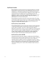
Power Problems 107
Detector Fuse 107
Vacuum Pump Fuse 107
Dual Plasma Controller Fuses 107
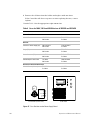
Table 4. Fuses for 100 V, 120 V and 230 V Versions of 355 SCD and 255 NCD 108
Figure 47. Fuse Positions on the Power Supply Board 108
Ozone Generation Problems 109
Ozone Generator 109
High Voltage Transformer 109
Plugged Restrictor Lines 110
Response Problems 111
Temperature Reading Problems 112
Diagnosing General Problems 113
Table 5. Troubleshooting Detector Issues 113
Table 6. Troubleshooting Pump Issues 115
Table 7. Troubleshooting Burner Issues 116
Index

16 Operation and Maintenance Manual

17
Agilent 355 Sulfur and 255 Nitrogen Chemiluminescence Detectors
Operation and Maintenance Manual
Agilent Technologies
1
Introduction
This manual will guide you in the installation, operation, and troubleshooting
of the Agilent 355 Sulfur Chemiluminescence Detector (SCD) and the Agilent
255 Nitrogen Chemiluminescence Detector (NCD). This manual is intended for
use with the Agilent 355 SCD or 255 NCD with the Dual Plasma Burner and
Controller.
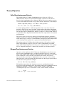
This operation and service manual has some important conventions, such as
the use of boxed warnings. This information is deliberately set out from the
text for emphasis and should be followed to assure operator safety and proper
instrumental operation.
If you are installing the 355 SCD or 255 NCD yourself, follow the installation
procedures described in the following sections. If your instrument is already
installed, turn to the Operation section to begin.

18 Operation and Maintenance Manual


20 Operation and Maintenance Manual
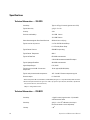
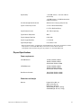
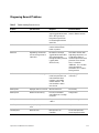
Specifications
Technical Information — 355 SCD
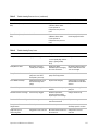
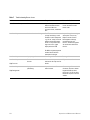
Technical Information — 255 NCD
Sensitivity
*
* Burner temperature 800 °C, 80 SCCM air, and 60 SCCM hyrdrogen, test compound dimethyl sulfide in toluene.
Typical < 0.5 pg S/second (signal to noise 3.3:1)
Typical Selectivity g S/g C > 2 x 10
7
Linearity >10
4
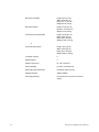
Precision and Stability
†
† Based on thiopene in benzene at 1 ppm mass sulfur, 1 µL injection split 1:10, 30 m, 0.32 mm ID, 1 µm thick CP
wax (n=10 for 2.5 hours; n=42 for 72 hours).
Subject to change without notice.
<2% RSD 2 hours
<5% RSD 72 hours
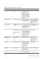
Ozone flow through the Post Ozone Restrictor 20-30 mL/min at 3-6 psig
Typical reaction cell pressure 4 - 8 Torr RV5 Oil Sealed Pump
6 - 12 Torr Dry Piston Pump
Typical Burner Pressure 250-400 Torr operating
Typical Burner Temperature 800 °C
Typical Air Flow Rate 65 SCCM recommended
3-10 SCCM recommended with FID adapter
Typical Hydrogen Flow Rate 40 SCCM recommended
Signal Output Ranges 0-1V, 0-10V
Typical time to reach 800 °C from room
temperature
10 min typical(120 VAC, 60 Hz)
Typical safety shroud outside temperature <65 °C at 800 °C Burner temperature typical
Recorder output 0-1 V or 0-10 V
Sensitivity <3 pg N/second (signal to noise 3:1) in both N
and nitrosamine modes
Selectivity g N/g C > 2 to 10
7
in N mode (selectivity in
nitrosamine mode is matrix-dependent)
Linearity >10
4
La pagina si sta caricando...
La pagina si sta caricando...
La pagina si sta caricando...
La pagina si sta caricando...
La pagina si sta caricando...
La pagina si sta caricando...
La pagina si sta caricando...
La pagina si sta caricando...
La pagina si sta caricando...
La pagina si sta caricando...
La pagina si sta caricando...
La pagina si sta caricando...
La pagina si sta caricando...
La pagina si sta caricando...
La pagina si sta caricando...
La pagina si sta caricando...
La pagina si sta caricando...
La pagina si sta caricando...
La pagina si sta caricando...
La pagina si sta caricando...
La pagina si sta caricando...
La pagina si sta caricando...
La pagina si sta caricando...
La pagina si sta caricando...
La pagina si sta caricando...
La pagina si sta caricando...
La pagina si sta caricando...
La pagina si sta caricando...
La pagina si sta caricando...
La pagina si sta caricando...
La pagina si sta caricando...
La pagina si sta caricando...
La pagina si sta caricando...
La pagina si sta caricando...
La pagina si sta caricando...
La pagina si sta caricando...
La pagina si sta caricando...
La pagina si sta caricando...
La pagina si sta caricando...
La pagina si sta caricando...
La pagina si sta caricando...
La pagina si sta caricando...
La pagina si sta caricando...
La pagina si sta caricando...
La pagina si sta caricando...
La pagina si sta caricando...
La pagina si sta caricando...
La pagina si sta caricando...
La pagina si sta caricando...
La pagina si sta caricando...
La pagina si sta caricando...
La pagina si sta caricando...
La pagina si sta caricando...
La pagina si sta caricando...
La pagina si sta caricando...
La pagina si sta caricando...
La pagina si sta caricando...
La pagina si sta caricando...
La pagina si sta caricando...
La pagina si sta caricando...
La pagina si sta caricando...
La pagina si sta caricando...
La pagina si sta caricando...
La pagina si sta caricando...
La pagina si sta caricando...
La pagina si sta caricando...
La pagina si sta caricando...
La pagina si sta caricando...
La pagina si sta caricando...
La pagina si sta caricando...
La pagina si sta caricando...
La pagina si sta caricando...
La pagina si sta caricando...
La pagina si sta caricando...
La pagina si sta caricando...
La pagina si sta caricando...
La pagina si sta caricando...
La pagina si sta caricando...
La pagina si sta caricando...
La pagina si sta caricando...
La pagina si sta caricando...
La pagina si sta caricando...
La pagina si sta caricando...
La pagina si sta caricando...
La pagina si sta caricando...
La pagina si sta caricando...
La pagina si sta caricando...
La pagina si sta caricando...
La pagina si sta caricando...
La pagina si sta caricando...
La pagina si sta caricando...
La pagina si sta caricando...
La pagina si sta caricando...
La pagina si sta caricando...
La pagina si sta caricando...
La pagina si sta caricando...
La pagina si sta caricando...
La pagina si sta caricando...
-
 1
1
-
 2
2
-
 3
3
-
 4
4
-
 5
5
-
 6
6
-
 7
7
-
 8
8
-
 9
9
-
 10
10
-
 11
11
-
 12
12
-
 13
13
-
 14
14
-
 15
15
-
 16
16
-
 17
17
-
 18
18
-
 19
19
-
 20
20
-
 21
21
-
 22
22
-
 23
23
-
 24
24
-
 25
25
-
 26
26
-
 27
27
-
 28
28
-
 29
29
-
 30
30
-
 31
31
-
 32
32
-
 33
33
-
 34
34
-
 35
35
-
 36
36
-
 37
37
-
 38
38
-
 39
39
-
 40
40
-
 41
41
-
 42
42
-
 43
43
-
 44
44
-
 45
45
-
 46
46
-
 47
47
-
 48
48
-
 49
49
-
 50
50
-
 51
51
-
 52
52
-
 53
53
-
 54
54
-
 55
55
-
 56
56
-
 57
57
-
 58
58
-
 59
59
-
 60
60
-
 61
61
-
 62
62
-
 63
63
-
 64
64
-
 65
65
-
 66
66
-
 67
67
-
 68
68
-
 69
69
-
 70
70
-
 71
71
-
 72
72
-
 73
73
-
 74
74
-
 75
75
-
 76
76
-
 77
77
-
 78
78
-
 79
79
-
 80
80
-
 81
81
-
 82
82
-
 83
83
-
 84
84
-
 85
85
-
 86
86
-
 87
87
-
 88
88
-
 89
89
-
 90
90
-
 91
91
-
 92
92
-
 93
93
-
 94
94
-
 95
95
-
 96
96
-
 97
97
-
 98
98
-
 99
99
-
 100
100
-
 101
101
-
 102
102
-
 103
103
-
 104
104
-
 105
105
-
 106
106
-
 107
107
-
 108
108
-
 109
109
-
 110
110
-
 111
111
-
 112
112
-
 113
113
-
 114
114
-
 115
115
-
 116
116
-
 117
117
-
 118
118


Agilent Technologies 355 SCD Manuale utente
- Tipo
- Manuale utente
- Questo manuale è adatto anche per
in altre lingue
Documenti correlati
-
Agilent Technologies TriScroll 300 Series Istruzioni per l'uso
-
Agilent Technologies 6106A Manuale utente
-
-
-
-
Altri documenti
-
 Hach ORBISPHERE 510 Basic User Manual
-
KitchenAid JS48CXFXDB01 Guida d'installazione
-
 Teledyne 317R Manuale utente
-
Hach TitraLab AT1102 Basic User Manual
-
 Hach TitraLab KF1000 Series Basic User Manual
-
 Hach NX7500 Manuale utente
-
 Hach 29971-72 Manuale utente
-
Dometic Kampa Geyser Istruzioni per l'uso
-
 Hach 9525sc Manuale utente
-
HP Treadmill 4328A Manuale utente


