Tascam MZ-372 Manuale del proprietario
- Categoria
- Mixer audio
- Tipo
- Manuale del proprietario

ENGLISH
FRANÇAIS
ESPAÑOL
DEUTSCH
ITALIANO
日本語
OWNER'S MANUAL
MODE D’EMPLOI
MANUAL DEL USUARIO
BEDIENUNGSANLEITUNG
MANUALE DI ISTRUZIONI
取扱説明書
LX372G0003
MZ-372
MIXER

2 TASCAM MZ-372
• TASCAMisatrademarkofTEACCORPORATION,
registeredintheU.S.andothercountries.
• Othercompanynames,productnamesand
logosinthisdocumentarethetrademarks
orregisteredtrademarksoftheirrespective
owners.
TEACCORPORATION
https://tascam.jp/jp/
Phone:+81-42-356-9143
1-47Ochiai,Tama-shi,Tokyo206-8530Japan
TEACAMERICA,INC.
https://tascam.com/us/
Phone:+1-323-726-0303
10410PioneerBlvd.Suite#1and#4,
SantaFeSprings,California90670,U.S.A.
TEACUKLtd.
https://tascam.eu/
Phone:+44-1923-797205
MeridienHouse,69-71ClarendonRoad,
Watford,Herts,WD171DS,UnitedKingdom
TEACEUROPEGmbH
https://tascam.de/
Phone:+49-611-71580
Bahnstrasse12,65205Wiesbaden-Erbenheim,
Germany
TEACSALES&TRADING(SHENZHEN)CO.,LTD
http://tascam.cn/
Phone:+86-755-88311561~2
Room817,XinianCenterA,TairanNineRoadWest,
ShennanRoad,FutianDistrict,Shenzhen,
GuangdongProvince518040,China

TASCAM MZ-372 3
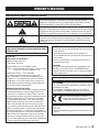
IMPORTANT SAFETY PRECAUTIONS
CAUTION: TO REDUCE THE RISK OF ELECTRIC SHOCK, DO NOT
REMOVE COVER (OR BACK). NO USER-SERVICEABLE PARTS INSIDE.
REFER SERVICING TO QUALIFIED SERVICE PERSONNEL.
The lightning flash with arrowhead symbol, within equilateral
triangle, is intended to alert the user to the presence of uninsulated
“dangerous voltage” within the product’s enclosure that may be of
sufficient magnitude to constitute a risk of electric shock to persons.
The exclamation point within an equilateral triangle is intended to
alert the user to the presence of important operating and mainte-
nance (servicing) instructions in the literature accompanying the
appliance.
WARNING: TO PREVENT FIRE OR SHOCK HAZ-
ARD, DO NOT EXPOSE THIS APPLIANCE TO RAIN
OR MOISTURE.
For U.S.A.
Declaration of Conformity
Model Number: MZ-372
Trade Name: TASCAM
Responsible party: TEAC AMERICA, INC.
Address: 10410 Pioneer Blvd. Suite #1 and #4, Santa
Fe Springs, California 90670, U.S.A.
Telephone number: 1-323-726-0303
This device complies with Part 15 of the FCC
Rules. Operation is subject to the following two
conditions: (1) this device may not cause harmful
interference, and (2) this device must accept any
interference received, including interference that
may cause undesired operation.
INFORMATION TO THE USER
This equipment has been tested and found to com-
ply with the limits for a Class B digital device, pur-
suant to Part 15 of the FCC Rules. These limits are
designed to provide reasonable protection against
harmful interference in a residential installation.
This equipment generates, uses, and can radiate
radio frequency energy and, if not installed and
used in accordance with the instruction manual,
may cause harmful interference to radio communi-
cations. However, there is no guarantee that inter-
ference will not occur in a particular installation. If
this equipment does cause harmful interference to
radio or television reception, which can be deter-
mined by turning the equipment off and on, the
user is encouraged to try to correct the interference
by one or more of the following measures.
a) Reorient or relocate the receiving antenna.
b) Increase the separation between the equipment
and receiver.
c) Connect the equipment into an outlet on a
circuit different from that to which the receiver is
connected.
d) Consult the dealer or an experienced radio/TV
technician for help.
CAUTION
Changes or modifications to this equipment not
expressly approved by TEAC CORPORATION for
compliance could void the user’s authority to oper-
ate this equipment.
IN USA/CANADA, USE ONLY ON 120 V SUPPLY.
For Canada
THIS CLASS B DIGITAL APPARATUS COMPLIES WITH
CANADIAN ICES-003.
CET APPAREIL NUMERIQUE DE LA CLASSE B EST
CONFORME A LA NORME NMB-003 DU CANADA.
This product complies with the
European Directives request and the
other Commission Regulations.
CE Marking Information
EN55103-2
a) Applicable electromagnetic environment: E1, E2,
E3, E4
OWNER’S MANUAL

4 TASCAM MZ-372
IMPORTANT SAFETY INSTRUCTIONS
1. Read these instructions.
2. Keep these instructions.
3. Heed all warnings.
4. Follow all instructions.
5. Do not use this apparatus near water.
6. Clean only with dry cloth.
7. Do not block any ventilation openings. Install in
accordance with the manufacturer’s instructions.
8. Do not install near any heat sources such as ra-
diators, heat registers, stoves, or other apparatus
(including amplifiers) that produce heat.
9. Do not defeat the safety purpose of the polar-
ized or grounding-type plug. A polarized plug
has two blades with one wider than the other. A
grounding type plug has two blades and a third
grounding prong. The wide blade or the third
prong are provided for your safety. If the provid-
ed plug does not fit into your outlet, consult an
electrician for replacement of the obsolete outlet.
10. Protect the power cord from being walked on
or pinched particularly at plugs, convenience
receptacles, and the point where they exit from
the apparatus.
11. Only use attachments/accessories specified by
the manufacturer.
12. Use only with the cart, stand, tripod, bracket, or
table specified by the manufacturer, or sold with
the apparatus. When a cart is used, use caution
when moving the cart/apparatus combination to
avoid injury from tip-over.
13. Unplug this apparatus during lightning storms or
when unused for long periods of time.
14. Refer all servicing to qualified service personnel.
Servicing is required when the apparatus has
been damaged in any way, such as power-supply
cord or plug is damaged, liquid has been spilled
or objects have fallen into the apparatus, the
apparatus has been exposed to rain or moisture,
does not operate normally, or has been dropped.
0The mains plug is used as the disconnect de-
vice, the disconnect device shall remain readily
operable.
0Caution should be taken when using earphones
or headphones with the product because exces-
sive sound pressure (volume) from earphones or
headphones can cause hearing loss.
0If you are experiencing problems with this prod-
uct, contact TEAC for a service referral. Do not use
the product until it has been repaired.
0Do not remove the external cases or cabinets to
expose the electronics. No user serviceable parts
are inside.
0If you are experiencing problems with this prod-
uct, contact the store where you purchased the
unit for a service referral. Do not use the product
until it has been repaired.
0Use of controls or adjustments or performance of
procedures other than those specified herein may
result in hazardous radiation exposure.
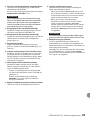
CAUTION
0Do not expose this apparatus to drips or
splashes.
0Do not place any objects filled with liquids, such
as vases, on the apparatus.
0Do not install this apparatus in a confined space
such as a book case or similar unit.
0The apparatus should be located close enough
to the AC outlet so that you can easily grasp the
power cord plug at any time.
0If the product uses batteries (including a battery
pack or installed batteries), they should not be
exposed to sunshine, fire or excessive heat.
0CAUTION for products that use replaceable
lithium batteries: there is danger of explosion
if a battery is replaced with an incorrect type of
battery. Replace only with the same or equiva-
lent type.

TASCAM MZ-372 5
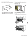
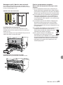
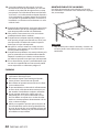
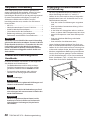
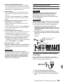
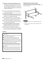
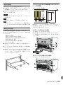
RACK-MOUNTING THE UNIT
Use the supplied rack-mounting kit to mount the unit
in a standard 19-inch rack, as shown below.
CAUTION
i Leave 1U of space above the unit for ventilation.
i Allow at least 10 cm (4 in) at the rear of the unit
for ventilation.
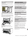
Rack-mounting using the universal holes
To use the universal holes of this unit to mount it in a
rack, install it with the rackmount screw kit as shown
in the illustrations below.
Universal Hole position
Installation in a 4U space
Use the a holes to mount the unit in the rack.
Installing this way creates gaps above and below the
MZ-372 (c).
These gaps can be used to route cables connected to
the back of the unit, for example.
Cable
Installation in a 3U or larger space
Use the b holes to mount the unit in the rack.

6 TASCAM MZ-372
For European Customers
Disposal of electrical and electronic equipment
(a) All electrical and electronic equipment should be
disposed of separately from the municipal waste
stream via designated collection facilities appoint-
ed by the government or the local authorities.
(b) By disposing of the electrical and electronic
equipment correctly, you will help save valuable
resources and prevent any potential negative
effects on human health and the environment.
(c) Improper disposal of waste equipment can have
serious effects on the environment and human
health as a result of the presence of hazardous
substances in electrical and electronic equipment.
(d) The crossed out wheeled dust bin symbol
indicates that electrical and electron-
ic equipment must be collected and
disposed of separately from household
waste.
(e) The return and collection systems are available
to the end users. For more detailed information
about disposal of old electrical and electronic
equipment, please contact your city office, waste
disposal service or the shop where you purchased
the equipment.
For China
“仅适用于海拔2000m 以下地区安全使用”
“仅适用于非熱帯气候条件下安全使用”
“環境保護使用年限”
产品有毒有害物质或元素的名称及含量
机种: MZ-372 有毒有害物质或元素
品名 铅
(Pb)
汞
(Hg)
镉
(Cd)
六价铬
(Cr6+)
多溴联苯
(PBB)
多溴二苯醚
(PBDE)
1 CHASSIS 部份 ○ ○ ○ ○ ○ ○
2 FRONT PANEL 部份 ○ ○ ○ ○ ○ ○
3 螺丝部份 ○ ○ ○ ○ ○ ○
4 线材部份 ○ ○ ○ ○ ○ ○
5 PCB Assy 部份 × ○ ○ ○ ○ ○
6 电源部份 ○ ○ ○ ○ ○ ○
7 附属品部份 × ○ ○ ○ ○ ○
8 LABEL 部份 ○ ○ ○ ○ ○ ○
9 包装部份 ○ ○ ○ ○ ○ ○
○ :表示该有毒有害物质在该部件所有均质材料中的含有量均在 GB/T26572 标准规定的限量要求以下。
× :表示该有毒有害物质至少在该部件的某一均质材料中的含量超出 GB/T26572 标准规定的限量要求。
(针对现在代替技术困难的电子部品及合金中的铅 ))

TASCAM MZ-372 7
Thank you very much for purchasing the TASCAM
MZ−372.
Before using this unit, read this Owner’s Manual care-
fully so that you will be able to use it correctly and
enjoy working with it for many years. After you have
finished reading this manual, please keep it in a safe
place for future reference.
You can also download this Owner’s Manual from the
TEAC Global Site (http://teac-global.com/).
Features
0Rackmount mixer with numerous input channels
and two pairs of main outputs
0Six input channels are equipped with gain con-
trols, LED level meters, three-band equalizers and
faders Mic or line input can be easily selected with
switches
0Independent front mic input with volume control
and two-band equalizer
0Talkover function automatically lowers back-
ground music volume according to mic volume
0Two main outputs with stereo LED level meters
0Sub output with volume control and mono/stereo
output format selection
0Headphone output with volume control can be
used for pre-fader monitoring of selected input
channels and the main output
03U rackmount size
Items included with this product
This product includes the following items.
Take care when opening the package to avoid
damaging the items. Keep the packing materials for
transportation in the future.
Please contact the store where you purchased this
unit if any of these items are missing or have been
damaged during transportation.
0Main unit ...........................................................................× 1
0AC adapter (TASCAM PS-M1524) ............................. × 1
0Cord for AC adapter (JAPAN USA/EUROPE) ..........× 2
0Rackmount screw kit .................................................... × 1
0Owner’s Manual (this document)
including warranty ........................................................× 1
CAUTION
Always use the included AC adapter (TASCAM
PS-M1524) when using this unit. Never use the
included AC adapter with any other device. Doing
so could cause damage, fire or electric shock.
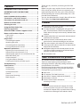
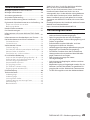
Contents
IMPORTANT SAFETY PRECAUTIONS....................... 3
IMPORTANT SAFETY INSTRUCTIONS ..................... 4
Features .................................................................... 7
Items included with this product ........................... 7
Conventions used in this manual ........................... 8
Precautions for placement and use ........................ 8
Beware of condensation ......................................... 8
Cleaning the unit ..................................................... 8
Using the TEAC Global Site ..................................... 8
Product registration ................................................ 8
About TASCAM customer support service ............. 8
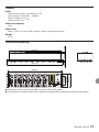
Names and functions of parts ................................ 9
Front panel ............................................................................9
Rear panel ........................................................................... 10
Preparation ............................................................ 11
Connecting the power ................................................... 11
Attaching the cord ........................................................... 11
Connecting other equipment...................................... 12
Turning the power on and off...................................... 13
Operation procedures ........................................... 14
Adjusting mic input channels (1-6)............................ 14
Adjusting line input channels (1-6) ........................... 14
Adjusting the input of a mic connected to the
MAIN MIC INPUT jack ...................................................... 14
Output channels ............................................................... 14
Using the talkover function .......................................... 15
Listening to channel pre-fader signals ..................... 15
Troubleshooting .................................................... 15
Specifications ......................................................... 16
Audio inputs ....................................................................... 16
Audio outputs ................................................................... 16
Audio performance ......................................................... 16
General ................................................................................. 17
Dimensional drawings.................................................... 17
Block diagram .................................................................... 18

8 TASCAM MZ-372
Conventions used in this manual
In this manual, we use the following conventions:
0The names of switches, connectors and other
physical parts of this unit are written using a bold
font like this: POWER switch.
0Additional information is provided as necessary as
tips, notes and cautions.
TIP
These are tips about how to use the unit.
NOTE
These provide additional explanations and de-
scribe special cases.
CAUTION
Failure to follow these instructions could result
in injury, damage to equipment or lost recording
data, for example.
Precautions for placement and use
0The operating temperature range of this unit is
5–35 °C.
0Do not install this unit in the following types of
locations. Doing so could cause malfunction.
Places with significant vibrations
Near windows or other places exposed to
direct sunlight
Near heaters or other extremely hot places
Extremely cold places
Places with bad ventilation or high humidity
Very dusty locations
0To enable good heat dissipation, do not place
anything on top of the unit.
0Do not place the unit on top of a power amplifier
or other device that generates heat.
Beware of condensation
If the unit is moved from a cold to a warm place,
or used after a sudden temperature change, there
is a danger of condensation; vapor in the air could
condense on the internal mechanism, making correct
operation impossible.
To prevent this, or if this occurs, let the unit sit for one
or two hours at the new room temperature before
using it.
Cleaning the unit
To clean the unit, wipe it gently with a soft dry cloth.
Do not wipe with chemical cleaning cloths, benzene,
thinner, alcohol or other chemical agents. Doing so
could damage the surface or cause discoloration.
Using the TEAC Global Site
You can download updates for this unit from the
TEAC Global Site:
http://teac-global.com/
In the TASCAM Downloads section, select the desired
language to open the Downloads website page for
that language.
Product registration
Customers in the USA, please visit the following TAS-
CAM website to register your TASCAM product online.
https://tascam.com/us/
About TASCAM customer support
service
TASCAM products are supported and warrantied only
in their country/region of purchase.
To receive support after purchase, on the TASCAM
Distributors list page of the TEAC Global Site (http://
teac-global.com/), search for the local company or
representative for the region where you purchased
the product and contact that organization.
When making inquiries, the address (URL) of the shop
or web shop where it was purchased and the pur-
chase date are required.
Moreover, the warranty card and proof of purchase
might also be necessary.

TASCAM MZ-372 9
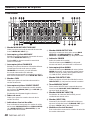
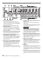
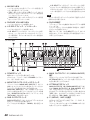
Names and functions of parts
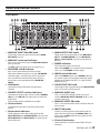
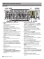
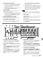
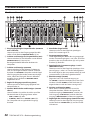
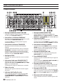
Front panel
1 MAIN MIC INPUT VOLUME knob
Use to adjust the mic input level from the MAIN
MIC INPUT jack (w).
2 MAIN MIC switch and indicator
Press to turn mic input from the MAIN MIC INPUT
jack (w) on/off.
The MIC indicator lights when mic input is on.
3 TALKOVER switch/indicator
Press to turn the talkover function on/off.
When the talkover function is on, the TALKOVER
indicator lights, and the levels of all input chan-
nels are lowered automatically when sound is
input from a mic connected to the MAIN MIC
INPUT.
4 GAIN knobs
Use these to adjust the levels of each input
channel.
5 SOURCE SELECT switches/indicators
Use these to set the input source to the C (MONO)
/MIC (h) or LINE A/B (v) input jacks on the back
of the unit.
The indicator for the selected input lights.
6 Channel faders
Use these to adjust the send levels of channel
signals.
7 Output level indicators
These indicators show the output levels of the
MAIN OUTPUTS 1-2 (UNBALANCED) (f) jacks and
MAIN OUTPUTS 1-2 (BALANCED) (c) jacks on the
back of the unit.
8 MAIN OUTPUT VOL knobs
These adjust the output levels of the MAIN OUT-
PUTS 1-2 (UNBALANCED) (f) and MAIN OUT-
PUTS 1-2 (BALANCED) (c) jacks on the back of
the unit.
9 POWER indicator
This shows the status of the unit.
When the POWER (a) switch on the back of the
unit is on, the POWER indicator lights.
0 MONO switch/indicator
When the MONO switch is on (MONO indicator
lit), mono signals will be output from the stereo
output buses (MAIN OUTPUT 1/2, SUB OUTPUT,
MONITOR OUT).
q SUB OUTPUT VOL knob
Use to adjust the output level of the SUB OUTPUT
jacks (x) on the back of the unit.
w MAIN MIC INPUT jack
This is an XLR/TRS combo jack for mic input.
Use the MAIN MIC INPUT VOLUME knob (1) to
set the input level.
e MAIN MIC INPUT EQ knobs
This is a 2-band equalizer (HIGH/LOW) for the mic
input sound.
r INPUTS EQ knobs
Use this 3-band equalizer (HIGH/MID/LOW) to
adjust the sound from the C (MONO) /MIC (h)
input jack or LINE A or B (v) input jacks on the
back of the unit.
t Channel level meters
These indicators show the input levels of input
channels.

10 TASCAM MZ-372
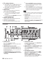
y PFL switches/indicators
o When a PFL switch is on (PFL indicator lit), the
pre-fader signal (signal before fader adjust-
ment) can be monitored through headphones.
o When a PFL switch is off, only the normal
monitoring sound is output.
u MIXING knob
Use this to mix the pre-fader and monitoring
signals output to the headphones.
o Turn all the way to the PFL side to monitor
channels that have their PFL (y) switches
pressed in.
o Turn all the way to the MONITOR side to moni-
tor the monitoring signal.
i PHONES VOLUME knob
Use this to adjust the headphone output level.
o L/R SPLIT switch/indicator
Press to change the headphone output mode.
o When the L/R SPLIT switch is on (indicator
lit), pre-fader signals are output from the left
channel and the monitoring signal is output
from the right channel.
o When the L/R SPLIT switch is off (indicator un-
lit), the monitoring signal is output. When PFL
switches are on, the pre-fader and monitoring
signals are mixed and output together.
NOTE
The PFL signals are mixed with the monitoring sig-
nal, so the selected PFL signals will sound louder.
p PHONES jack
Use this standard stereo jack to connect stereo
headphones.
Use an adapter to connect headphones with a
mini plug.
The monitoring and PFL signals can be monitored,
depending on the PFL (y) and L/R SPLIT (o)
switch settings.
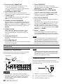
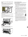
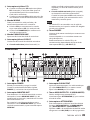
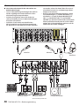
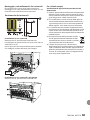
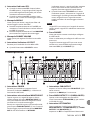
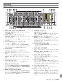
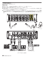
Rear panel
a POWER switch
Press to turn the unit on and off.
When on, the POWER (9) indicator lights on the
front of the unit.
s MONITOR OUT mic mix switch
This sets whether or not the input signal from a
mic connected to the MAIN MIC INPUT (w) jack
on the front of the unit is sent to and mixed with
the monitoring output.
To mix the input signal from a mic connected to
the MAIN MIC INPUT (w) jack with the monitor-
ing output, set the MONITOR OUT mic mix switch
to WITH MIC.
d SUB OUTPUT switch
Set whether the output from the SUB OUTPUT
(x) jacks is stereo or mono.
Set it to MONO for mono output.
f MAIN OUTPUTS 1-2 (UNBALANCED) jacks
These analog outputs are RCA pin jacks.
Use the ATTENUATOR (g) switch to change the
output level.
g ATTENUATOR switches
These switch the output levels from the MAIN
OUTPUTS 1-2 (UNBALANCED) (f) and MAIN
OUTPUTS 1-2 (BALANCED) (c) jacks.
Set them to OFF if the destination amplifier
receives high gain, and set it to ON (-6dB) if the
destination amplifier receives low gain.

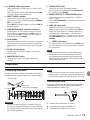
TASCAM MZ-372 11
h C (MONO) /MIC input jacks
These are analog XLR input jacks (1: GND, 2: HOT,
3: COLD).
Their input gains can be adjusted using the GAIN
(4) knobs on the front of the unit.
j INPUT LEVEL switches
Use these to set the input levels of the input
sources (mic or line) connected to the C (MONO) /
MIC (h) input jacks.
Set to MIC for mic level signals, and set to LINE for
line level signals.
k LINE/PHONO input selection switches
For channels 2–4, if the output of a CD player or
similar device is connected to a LINE A input (v)
jack, set this to LINE. If a record player output is
connected, set it to PHONO.
l Cord holder
Attach the power cord of the included AC adapter
(TASCAM PS-M1524) here to prevent accidental
disconnection. (See “Attaching the cord” on page
11.)
; DC IN 15V connector
Connect the included AC adapter (TASCAM PS-
M1524) here.
z MONITOR OUT jacks
These RCA pin jacks are analog monitoring
outputs.
x SUB OUTPUT jacks
These RCA pin jacks are analog outputs.
Mono signals will be output if the SUB OUTPUT
(d) switch is set to MONO.
c MAIN OUTPUTS 1-2 (BALANCED) jacks
These analog outputs are XLR jacks. (1: GND, 2:
HOT, 3: COLD)
Use the ATTENUATOR (g) switches to change the
output levels.
v LINE A/B input jacks
These RCA pin jacks are analog line outputs.
Record players can be connected to the LINE A
input jacks of channels 2–4. When connecting
a record player to these jacks, also connect its
grounding wire to the | (GND) jack (b), and set
the LINE/PHONO input selection switch (k) to
PHONO.
b
| (GND) connectors
If a record player is connected to the LINE A input
(v) jacks of channel 2–4, also connect its ground-
ing wire to this.
NOTE
If a humming noise occurs when connecting a
device other than a record player, connecting
a grounding wire from the metal frame of that
device (or the rack frame if rackmounted) to this
could reduce the noise.
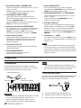
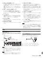
Preparation
Connecting the power
Use the included AC adapter (TASCAM PS-M1524) to
connect a power supply to the unit as shown below.
Power outlet
DC plug
TASCAM
PS-M1524 (included)
CAUTION
Always use the AC adapter (TASCAM PS-M1524)
that was packaged with the unit. Using a different
AC adapter could cause malfunction, overheating,
fire or other problems.
NOTE
The AC adapter for the unit includes two types of
adapter cords. Attach the type of AC adapter cord
that matches the power outlet that you are using.
Attaching the cord
In order to prevent the cord from becoming discon-
nected during use, attach it to the cord holder (l)
when connecting it to the unit.
1. Remove the cord holder (l) screw.
2. Place the cord in the cord holder (l).
3. Tighten the cord holder (l) screw.

12 TASCAM MZ-372
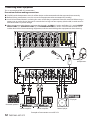
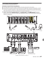
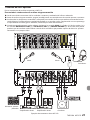
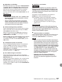
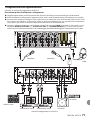
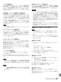
Connecting other equipment
This is an example of MZ-372 connections.
Precautions before making connections
0Carefully read the operation manuals of the devices to be connected and then connect them correctly.
0Before making connections, turn this unit and all equipment to be connected off (standby).
0Install all connected devices, including this unit, so that they are powered from the same line. When using a
power strip or similar device, be sure to use one that has high current capacity (thick cable) in order to mini-
mize fluctuations in power voltage.
0When connecting audio devices, minimize the channel 1–6 GAIN (4) knobs and faders (6), and the MAIN
OUTPUT VOL (8), SUB OUTPUT VOL (q) and PHONES VOLUME (i) knobs. Failure to do so could cause
sudden loud noises from monitoring equipment, and this could damage the equipment or harm hearing.
Powered speakers
Headphones
CD player
Record player
Mic Mic
Stereo amplifierStereo amplifier
Examples of connections to an MZ-372

TASCAM MZ-372 13
Connecting microphones
Mics can be connected to the MAIN MIC INPUT (w)
jack on the front of the unit or to one of the channel
1–6 C (MONO) /MIC (h) input jacks on the back of
the unit with the INPUT LEVEL (j) switch set to MIC.
Connecting electronic devices and other
audio equipment
When connecting an electronic device or other audio
equipment, connect it to channel 1–6 C (MONO) /
MIC (h) input jacks, and set the INPUT LEVEL switch
(j) to LINE. The device can be connected to channel
1–6 LINE A or B (v) input jacks.
When connected to channel 2–4 LINE A (v) input
jacks, set the LINE/PHONO (k) input switch to LINE.
NOTE
The C (MONO) /MIC (h) jacks are mono inputs.
Connecting record players
When connecting a record player, connect it to
channel 2–4 LINE A (v) input jacks, and set the LINE/
PHONO (k) input switch to PHONO.
Connect the grounding wire from the record player
to the | (GND) (b) connector.
Connecting monitor speakers
Connect monitor speakers (powered speakers or an
amplifier and speaker system) to the MONITOR OUT
(z) jacks.
To mix in the mic input signal from the MAIN MIC
INPUT (w) jack, and output it from the monitor
speakers, set the MONITOR OUT (s) mic mix switch
to WITH MIC.
Connecting headphones
Connect headphones to the PHONES (p) jack (stan-
dard stereo).
You can monitor input channel pre-fader signals and
the signal before it is sent to the stereo output bus.
CAUTION
Before connecting headphones, minimize the vol-
ume with the PHONES VOLUME (i) knob. Failure
to do so could result in a sudden loud noise that
could harm hearing, for example.
NOTE
Since the headphone sound is output from the
monitoring bus, the position of the MAIN OUT-
PUT VOL (8) knob has no effect on it.
Connecting stereo amplifiers
When connecting a stereo amplifier, connect it to the
MAIN OUTPUTS 1-2 (UNBALANCED) (f) or MAIN
OUTPUTS 1-2 (BALANCED) (c) jacks.
TIP
i When connecting 2 or more amplifier and speaker
systems, including main and sub, main and mon-
itoring, or front and rear combinations, using the
MAIN OUTPUTS 1-2 (UNBALANCED) (f), MAIN
OUTPUTS 1-2 (BALANCED) (c), and SUB OUT-
PUT (x) jacks could be convenient. Moreover, the
outputs of the jacks are independent and have
their own dedicated output knobs, so you can set
the output levels separately with this unit.
i By connecting a recorder to MONITOR OUT
(z) jacks, the signal output to amplifier/speaker
systems can be recorded.
Turning the power on and off
CAUTION
i Turn down the volume of the sound system con-
nected to the unit before starting up or shutting
down the unit.
i Do not wear connected headphones when turn-
ing the unit on and off. Loud noises could damage
the speakers or harm your hearing.
Before turning the power on
1. Make the following settings on the front of the
unit.
o EQ knobs w center values
o Other knobs w all the way left (MIN side)
o Faders w all the way down
o Switches w off (not pushed in)
2. Minimize the output levels of audio sources and
input levels of amplifiers connected to this unit.
Turning the power on
1. Use the POWER (a) switch on the back of the
unit to turn its power on.
The POWER (9) indicator on the front of the unit
will light when on.
2. Turn connected input audio source devices on.
3. Finally turn amplifiers on.
Turning the power off
Follow the procedures above in reverse when turning
the power off.
Failure to follow the correct order could result in
clicking noises, for example, that might damage
equipment.

14 TASCAM MZ-372
Operation procedures
After turning the power on, adjust the levels of the
input signals.
Adjusting mic input channels (1-6)
1. Set the channel 1–6 GAIN (4) and EQ (r) knobs
to their center values.
2. Press the channel 1–6 SOURCE SELECT (5) C/
MIC switches so the C/MIC indicators (2) light.
3. When connecting a mic to a channel 1–6 C
(MONO) /MIC (h) input jack, set the INPUT
LEVEL switch (j) to MIC.
4. Set the MAIN OUTPUT VOL (8) knob levels low.
5. Try speaking into the mic.
Use the channel 1–6 GAIN (4) knob to adjust
the input level so that its level meter (t) lights
around 0 dB.
6. Use the channel 1–6 EQ (r) knobs to adjust the
equalizer.
7. Follow the above procedures for other input
channels with connected mics.
Adjusting line input channels (1-6)
1. Set the channel 1–6 GAIN (4) and EQ (r) knobs
to their center values.
2. When connecting an audio device to channel
1–6, press the SOURCE SELECT switch (5), so
that the SOURCE SELECT indicator (A/B/C/MIC)
lights.
3. When connecting an audio device to a channel
1–6 C (MONO) /MIC (h) input jack, set the
INPUT LEVEL switch (j) to LINE.
When connecting an audio device to channel 1–6
LINE A/B (v) input jacks, set the LINE/PHONE
switch (k) to LINE.
4. Set the MAIN OUTPUT VOL (8) knob levels low.
5. Start playback on the connected audio device.
Use the channel 1–6 GAIN (4) knob to adjust
the input level so that its level meter (t) lights
around 0 dB.
6. Use the channel 1–6 EQ (r) knobs to adjust the
equalizer.
7. Follow the above procedures to adjust other
input channels with connected audio devices.
Adjusting the input of a mic connected
to the MAIN MIC INPUT jack
1. Connect a mic to the MAIN MIC INPUT jack (w),
and press the MAIN MIC (2) switch so the MAIN
MIC (2) indicator lights.
2. Use the MAIN MIC INPUT VOLUME (1) knob to
adjust the mic input level.
3. Use the MAIN MIC INPUT EQ (e) knobs to adjust
the 2-band (HIGH/LOW) equalizer for the mic
sound.
Output channels
Output signals can be sent to the following jacks from
the stereo output bus.
0MAIN OUTPUTS 1-2 (UNBALANCED) (f) and
MAIN OUTPUTS 1-2 (BALANCED) (c) jacks
0SUB OUTPUT (x) jacks
0MONITOR OUT (z) jacks
NOTE
The output level from the MONITOR OUT (z)
jacks cannot be adjusted.
Adjusting the levels output from the MAIN
OUTPUTS 1-2 (UNBALANCED) and MAIN
OUTPUTS 1-2 (BALANCED) jacks
While checking the output level indicators (7), use
the channel faders (6) and MAIN OUTPUT VOL (8)
knobs to adjust the output levels. The optimal output
level adjustment is usually when the output level
indicators (7) light around 0 dB.
When an amplifier is connected to the MAIN OUT-
PUTS 1-2 (UNBALANCED) (f) or MAIN OUTPUTS
1-2 (BALANCED) (c) jacks, set the ATTENUATOR (g)
switch to OFF if it accepts high gain or ON (-6dB) if it
accepts low gain.
Adjusting the level output from the SUB
OUTPUT jacks
Use the SUB OUTPUT VOL (q) knob to adjust the
output level.
If the MONO (0) switch is set to ON (MONO indicator
lit) mono signals will be output from all output jacks.
To output mono signals from only the SUB OUTPUT
(x) jacks, set the SUB OUTPUT (d) switch to MONO.

TASCAM MZ-372 15
Using the talkover function
When the talkover function is turned on by pressing
the TALKOVER (3) switch, the levels of channels 1–6
will be automatically lowered when sound is input
from a mic connected to the MAIN MIC INPUT (w)
jack, making the mic signal easier to hear.
To turn the talkover function off, press the TALKOVER
(3) switch to turn it off (TALKOVER (3) indicator
becomes unlit).
Listening to channel pre-fader signals
By pressing the PFL (y) switches of channels to turn
them on, you can enable headphone monitoring of
individual channels 1–6, even when their faders (6)
are set at minimum values.
You can also monitor the signal before it is sent to the
stereo output bus.
1. Press the PFL (y) switches for the channels you
want to monitor so that their PFL indicators light,
and turn the MIXING (u) knob to PFL.
To monitor the signal before it is sent to the
stereo output bus, turn the MIXING (u) knob to
MONITOR.
2. After making mixing adjustments, use the
PHONES VOLUME (i) knob to adjust the moni-
toring output level.
NOTE
i The L/R SPLIT (o) switch can be turned on/off to
change the headphone output mode.
i When the L/R SPLIT switch (o) is on (indicator
lit), the pre-fader signals are output from the left
channel and the monitoring signal is output from
the right channel.
i When the L/R SPLIT switch (o) is off (indicator
unlit), the pre-fader signals and the monitoring
signal are mixed and output together from both
headphone channels.
i When the PFL (y) switch is off, if the L/R SPLIT
(o) switch is set to on, the monitoring signal
will be output from the right channel and no
sound will be output from the left channel of the
headphones.
Troubleshooting
If you are having trouble with the operation of this
unit, please try the following before seeking repair.
If these measures do not solve the problem, please
contact the store where you purchased this unit or
TASCAM customer support service.
The unit will not turn on.
0Confirm that the AC adapter (TASCAM PS-M1524)
is securely connected to both the outlet and the
DC jack.
Sound is not output from speakers connect-
ed via the MAIN OUTPUTS 1-2 jacks.
0Check the settings and volume of the connected
amplifier.
0Confirm that channel faders (6) are raised.
0Confirm that the input sound source is connected
properly.
The volume is low even when faders are
raised.
0Confirm that the GAIN (4) knobs for channels 1–6
are set properly.
0If mics are being input on channels 1–6, confirm
that the INPUT LEVEL (j) switches are set to
LINE.
The sound is distorted.
0Confirm that the GAIN (4) knobs for channels 1–6
are set properly.
0Confirm that the EQ is not set too high.
0Confirm that the channel 1–6 (6) faders and
MAIN OUTPUT VOL (8) knob are not set too
high.
Sound from a record player is strange.
0Confirm that it is connected to channel 2–4 LINE
A (v) input jacks and the LINE/PHONO (k) input
switch is set to PHONO.
0Confirm that the grounding wire from the record
player is connected to the | (GND) (b) connec-
tor.
A connected device is making a humming
noise.
0Connect a grounding wire from the metal frame
of the connected device to the |(GND) (b)
connector on this unit.
No sound is output from the monitoring sys-
tem connected to the MONITOR OUT jacks.
0Check the settings of the connected monitoring
system.
0Confirm that the channel 1–6 GAIN (4) knobs and
channel faders (6) are raised.

16 TASCAM MZ-372
Specifications
Audio inputs
MAIN MIC INPUT (BALANCED) jacks
Connectors:
XLR-3-31 (1: GND, 2: HOT, 3: COLD)
6.3mm (1/4”) standard TRS jacks (Tip: HOT,
Ring: COLD, Sleeve: GND)
Input impedance: 33 kΩ
Nominal input level: -65 dBu
(VOLUME knob at MAX)
Nominal input level: -30 dBu
(VOLUME knob at MIN)
INPUTS: MIC (BALANCED) jacks
Connectors: XLR-3-31 (1: GND, 2: HOT, 3: COLD)
Set to MIC
Maximum input level: -30 dBu
Minimum input level: -65 dBu
Input impedance: 33 kΩ
Set to LINE (UNBALANCED)
Nominal input level: -1 dBu
Maximum input level: 20 dBu
Input impedance: 22 kΩ
INPUTS: LINE (UNBALANCED) jacks
Connectors: RCA pin jacks
Nominal input level: -10 dBV
Maximum input level: 10 dBV
Input impedance: 22 kΩ
00 dBu=0.775 Vrms, 0 dBV=1 V
Audio outputs
MAIN OUTPUTS (UNBALANCED) jacks
Connectors: RCA pin jacks
Rated output level: -10 dBV
Maximum output level: 10 dBV
Output impedance: 200 Ω
MAIN OUTPUTS (BALANCED) jacks
Connectors: XLR-3-32 (1: GND, 2: HOT, 3: COLD)
Rated output level: 4 dBu
Maximum output level: 24 dBu
Output impedance: 200 Ω
SUB OUTPUT connectors
Connectors: RCA pin jacks
Rated output level: -16 dBV
Maximum output level: 0 dBV
Output impedance: 200 Ω
MONITOR OUT jacks
Connectors: RCA pin jacks
Rated output level: -16 dBV
Maximum output level: 0 dBV
Output impedance: 200 Ω
PHONES jack
Connectors: 6.3mm (1/4”) standard stereo jack
Maximum output: 50 mW + 50 mW
(into 32 Ω load)
00 dBu=0.775 Vrms, 0 dBV=1 V
Audio performance
Frequency response
20 Hz–20 kHz (INPUTS LINE to MAIN OUTPUTS)
Distortion
0.03% or less (INPUTS LINE to MAIN OUTPUTS)
S/N ratio
80 dB or more (INPUTS LINE to MAIN OUTPUTS)
Crosstalk
65 dB or more (INPUTS LINE to MAIN OUTPUTS)

TASCAM MZ-372 17
General
Power
Dedicated AC adapter (TASCAM PS-M1524)
Input voltage: AC 100–240V ~, 50/60Hz
Output voltage: DC 15V
Output current: 2.4 A
Power consumption
35 W
Dimensions
482.0 × 132.0 × 93.2 mm (width × height × depth, including protrusions)
Weight
3.2 kg
Dimensional drawings
462.0mm
482.0mm
76.0mm
120.7mm
18.3mm 63.2mm 11.7m
m
442.2mm
132.0mm
0Illustrations in this manual might differ in part from the actual product.
0Specifications and external appearance might be changed without notification to improve the product.

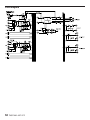
18 TASCAM MZ-372
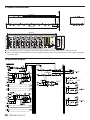
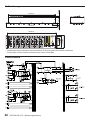
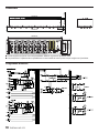
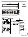
Block diagram

TASCAM MZ-372 19
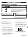
PRÉCAUTIONS DE SÉCURITÉ IMPORTANTES
ATTENTION: POUR RÉDUIRE LE RISQUE D'ÉLECTROCUTION, NE RETIREZ
PAS LE CAPOT (OU L'ARRIÈRE). AUCUNE PIÈCE INTERNE N'EST RÉPARABLE
PAR L'UTILISATEUR. CONFIEZ TOUTE RÉPARATION À UN SERVICE APRÈS-
VENTE QUALIFIÉ.
Le symbole d'éclair à tête de flèche dans un triangle équilatéral sert à
prévenir l'utilisateur de la présence dans l'enceinte du produit d'une «ten-
sion dangereuse» non isolée d'une grandeur suffisante pour constituer
un risque d'électrocution pour les personnes.
Le point d'exclamation dans un triangle équilatéral sert à prévenir
l'utilisateur de la présence d'instructions importantes de fonctionnement
et de maintenance (entretien) dans les documents accompagnant
l'appareil.
AVERTISSEMENT: POUR PRÉVENIR LES RISQUES
D'INCENDIE ET D'ÉLECTROCUTION, N'EXPOSEZ PAS
CET APPAREIL À LA PLUIE NI À L'HUMIDITÉ.
AUX USA/CANADA, UTILISEZ UNIQUEMENT UNE
TENSION D'ALIMENTATION DE 120 V.
Pour le Canada
THIS CLASS B DIGITAL APPARATUS COMPLIES WITH
CANADIAN ICES-003.
CET APPAREIL NUMÉRIQUE DE LA CLASSE B EST
CONFORME À LA NORME NMB-003 DU CANADA.
Ce produit est conforme aux impératifs
des directives européennes et autres
règlements de la Commission.
Informations sur le marquage CE
EN55103-2
a) Environnement électromagnétique applicable: E1,
E2, E3, E4
INSTRUCTIONS DE SÉCURITÉ IMPORTANTES
1. Lisez ces instructions.
2. Conservez ces instructions.
3. Tenez compte de tous les avertissements.
4. Suivez toutes les instructions.
5. N'utilisez pas cet appareil avec de l'eau à proximité.
6. Nettoyez-le uniquement avec un chiffon sec.
7. Ne bloquez aucune ouverture de ventilation. Instal-
lez-le conformément aux instructions du fabricant.
8. Ne l'installez pas près de sources de chaleur telles
que des radiateurs, bouches de chauffage, poêles
ou autres appareils (y compris des amplificateurs)
dégageant de la chaleur.
9. Ne neutralisez pas la fonction de sécurité de la fiche
polarisée ou de terre. Une fiche polarisée a deux
broches, l'une plus large que l'autre. Une fiche de
terre a deux broches identiques et une troisième
broche pour la mise à la terre. La broche plus large
ou la troisième broche servent à votre sécurité. Si la
fiche fournie n'entre pas dans votre prise, consultez
un électricien pour le remplacement de la prise
obsolète.
10. Évitez de marcher sur le cordon d'alimentation et
de le pincer, en particulier au niveau des fiches, des
prises secteur, et du point de sortie de l'appareil.
11. N'utilisez que des fixations/accessoires spécifiés par
le fabricant.
MODE D'EMPLOI

20 TASCAM MZ-372
12. Utilisez-le uniquement avec le chariot, socle, trépied,
support ou table spécifié par le fabricant ou vendu
avec l'appareil. Si un chariot est utilisé, faites atten-
tion à ne pas être blessé par un renversement lors du
déplacement de l'ensemble chariot/appareil.
13. Débranchez cet appareil en cas d'orage ou de non
utilisation prolongée.
14. Confiez toute réparation à des techniciens
de maintenance qualifiés. Une réparation est
nécessaire si l'appareil a été endommagé d'une
quelconque façon, par exemple si le cordon ou
la fiche d'alimentation est endommagé, si du li-
quide a été renversé sur l'appareil ou si des objets
sont tombés dedans, si l'appareil a été exposé
à la pluie ou à l'humidité, s'il ne fonctionne pas
normalement, ou s'il est tombé.
0La fiche secteur est utilisée comme dispositif de dé-
connexion et doit donc toujours rester disponible.
0Des précautions doivent être prises en cas d'utilisa-
tion d'écouteurs ou d'un casque avec le produit car
une pression sonore excessive (volume trop fort) dans
les écouteurs ou dans le casque peut causer une perte
auditive.
0Si vous rencontrez des problèmes avec ce produit,
contactez TEAC pour une assistance technique.
N'utilisez pas le produit tant qu'il n'a pas été réparé.
0Ne retirez pas les capots externes ou boîtiers pour
exposer l’électronique. aucune pièce interne n’est
réparable par l’utilisateur.
0Si vous rencontrez des problèmes avec ce produit,
contactez le magasin où vous avez acheté l’unité.
n’utilisez pas le produit tant qu’il n’a pas été réparé.
0L’utilisation de commandes, de réglages ou le suivi
de procédures autres que ce qui est décrit dans ce
document peut provoquer une exposition à un rayon-
nement dangereux.
ATTENTION
0N'exposez pas cet appareil aux gouttes ni aux
éclaboussures.
0Ne placez pas d'objet rempli de liquide sur l'appa-
reil, comme par exemple un vase.
0N’installez pas cet appareil dans un espace confiné
comme une bibliothèque ou un meuble similaire.
0L’appareil doit être placé suffisamment près de
la prise de courant pour que vous puissiez à tout
moment attraper facilement la fiche du cordon
d'alimentation.
0Si le produit utilise des piles/batteries (y compris
un pack de batteries ou des batteries fixes), elles ne
doivent pas être exposées au soleil, au feu ou à une
chaleur excessive.
0PRÉCAUTION pour les produits qui utilisent des
batteries remplaçables au lithium: remplacer une
batterie par un modèle incorrect entraîne un risque
d'explosion. Remplacez-les uniquement par un
type identique ou équivalent.
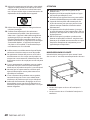
MONTAGE EN RACK DE L'UNITÉ
Utilisez le kit de montage en rack pour monter l'unité
dans un rack 19" standard, comme représenté ci-dessous.
ATTENTION
i Laissez 1U d'espace au-dessus de l'unité pour la
ventilation.
i Laissez au moins 10 cm à l'arrière de l'unité pour la
ventilation.
La pagina si sta caricando...
La pagina si sta caricando...
La pagina si sta caricando...
La pagina si sta caricando...
La pagina si sta caricando...
La pagina si sta caricando...
La pagina si sta caricando...
La pagina si sta caricando...
La pagina si sta caricando...
La pagina si sta caricando...
La pagina si sta caricando...
La pagina si sta caricando...
La pagina si sta caricando...
La pagina si sta caricando...
La pagina si sta caricando...
La pagina si sta caricando...
La pagina si sta caricando...
La pagina si sta caricando...
La pagina si sta caricando...
La pagina si sta caricando...
La pagina si sta caricando...
La pagina si sta caricando...
La pagina si sta caricando...
La pagina si sta caricando...
La pagina si sta caricando...
La pagina si sta caricando...
La pagina si sta caricando...
La pagina si sta caricando...
La pagina si sta caricando...
La pagina si sta caricando...
La pagina si sta caricando...
La pagina si sta caricando...
La pagina si sta caricando...
La pagina si sta caricando...
La pagina si sta caricando...
La pagina si sta caricando...
La pagina si sta caricando...
La pagina si sta caricando...
La pagina si sta caricando...
La pagina si sta caricando...
La pagina si sta caricando...
La pagina si sta caricando...
La pagina si sta caricando...
La pagina si sta caricando...
La pagina si sta caricando...
La pagina si sta caricando...
La pagina si sta caricando...
La pagina si sta caricando...
La pagina si sta caricando...
La pagina si sta caricando...
La pagina si sta caricando...
La pagina si sta caricando...
La pagina si sta caricando...
La pagina si sta caricando...
La pagina si sta caricando...
La pagina si sta caricando...
La pagina si sta caricando...
La pagina si sta caricando...
La pagina si sta caricando...
La pagina si sta caricando...
La pagina si sta caricando...
La pagina si sta caricando...
La pagina si sta caricando...
La pagina si sta caricando...
La pagina si sta caricando...
La pagina si sta caricando...
La pagina si sta caricando...
La pagina si sta caricando...
La pagina si sta caricando...
La pagina si sta caricando...
La pagina si sta caricando...
La pagina si sta caricando...
-
 1
1
-
 2
2
-
 3
3
-
 4
4
-
 5
5
-
 6
6
-
 7
7
-
 8
8
-
 9
9
-
 10
10
-
 11
11
-
 12
12
-
 13
13
-
 14
14
-
 15
15
-
 16
16
-
 17
17
-
 18
18
-
 19
19
-
 20
20
-
 21
21
-
 22
22
-
 23
23
-
 24
24
-
 25
25
-
 26
26
-
 27
27
-
 28
28
-
 29
29
-
 30
30
-
 31
31
-
 32
32
-
 33
33
-
 34
34
-
 35
35
-
 36
36
-
 37
37
-
 38
38
-
 39
39
-
 40
40
-
 41
41
-
 42
42
-
 43
43
-
 44
44
-
 45
45
-
 46
46
-
 47
47
-
 48
48
-
 49
49
-
 50
50
-
 51
51
-
 52
52
-
 53
53
-
 54
54
-
 55
55
-
 56
56
-
 57
57
-
 58
58
-
 59
59
-
 60
60
-
 61
61
-
 62
62
-
 63
63
-
 64
64
-
 65
65
-
 66
66
-
 67
67
-
 68
68
-
 69
69
-
 70
70
-
 71
71
-
 72
72
-
 73
73
-
 74
74
-
 75
75
-
 76
76
-
 77
77
-
 78
78
-
 79
79
-
 80
80
-
 81
81
-
 82
82
-
 83
83
-
 84
84
-
 85
85
-
 86
86
-
 87
87
-
 88
88
-
 89
89
-
 90
90
-
 91
91
-
 92
92


Tascam MZ-372 Manuale del proprietario
- Categoria
- Mixer audio
- Tipo
- Manuale del proprietario
in altre lingue
- français: Tascam MZ-372 Le manuel du propriétaire
- 日本語: Tascam MZ-372 取扱説明書