
PRODUCT DESCRIPTION AND INTENDED USE
This transmitter is part of the “Era-P” / “Era-W” Nice range.
The transmitters of these two ranges are used to control au-
tomation mechanisms for awnings, outdoor sunblinds or
blinds: any other use is improper and forbidden!
Functional specifications
• The “Era-P” range consists of portable models (“P”) while the
“Era-W” range consists of wall mounted models (“W”). • 1 or
6 “unit” models are available to send commands to, as well as
models with commands for the management of the weather
sensors. • Some models are provided with a hook to tem-
porarily hang the transmitter on the wall, others are provided
with a plate to mount it on the wall. To install this accessory
please refer to fig. 2 or 3. • Fig. 1 reports all the keys which
may be on the transmitters, based on the model. Their use is
as follows:
A - “Unit” keys (only in the P6, P6S, W6, W6S models): are
required to select the automation mechanism/s to send
the commands to. While memorising the transmitter, it is
necessary to programme at least one of these keys, as-
sociating at least one automation mechanism/s to them.
This makes the key a “unit for the reception of the com-
mands”, meaning that the automation mechanisms asso-
ciated to it will receive the same commands during the use
of the transmitter. The other keys available may be pro-
grammed in a similar manner, based on the system’s
needs. For all purposes, it is like having 6 independent
transmitters in a single command device.
B - Command keys (in all the models): are required to send
the rise (▲), stop (■) and lower (▼) commands. In the P6,
P6S, W6, W6S models, prior to sending a command, se-
lect the “unit” to send the command to.
C - Control keys of the automatic commands (only in the
P1S, P6S, W1S, W6S models): the key enables (the
key disables) the reception by the motor of the auto-
matic commands transmitted by any weather sensor in
the installation. When is pressed the system sets the
automatic operating mode of the automation mechanism
whereas when is pressed the system sets the manual
operating mode of the automation mechanism. The
“Wind” sensor may not be disabled since it is required to
protect the automation mechanism from wind damage.
With the automatic operating mode enabled, the user
may send manual commands any time. For more infor-
mation please refer to the manual of the automation
mechanism and the weather sensor.
D - Programming keys (in all the models): in the compatible
motors (e.g. those of the Era Mat range), these keys are
required to simplify the performance of the programming
procedures: the PRG key speeds up the access to the
procedures, whereas the ESC key speeds up the exit from
them. To access the keys remove the battery cover.
In the P6, P6S, W6, W6S models: during the execution of
the procedures, when pressing these keys is required, it is
necessary to firstly select the single “unit” where the pro-
cedure is being performed.
TESTING THE TRANSMITTER
Before memorising the transmitter in the receiver of the motor,
check its proper operation by pressing any key and observing
whether the LED lights up (fig. 1-E). If it does not, refer to the
section entitled “Replacing the Battery” in this manual.
SPECIFIC FUNCTIONS OF THE TRANSMITTER
• Select a “unit” to send a command to (only for the P6,
P6S, W6, W6S models)
With these transmitter models, prior to sending a command it
is necessary to select the “unit” (i.e. the automation mecha-
nisms associated to this) to send the command to. After se-
lecting the unit, its LED remains lit for a few seconds and,
before its turns off, it is possible to select other units to be
added to the first selected (to eliminate a unit selected by mis-
take, turn off its LED by briefly pressing the associated key).
After selecting the units desired, when their LEDs automatically
turn off, the units will remain in the transmitter’s memory until
a new unit/s is/are selected. While they remain in the memory
it will be possible to send them commands without having to
select them first.
• Enable or disable the reception of the automatic com-
mands sent from a weather sensor (only for the P1S,
P6S, W1S, W6S models)
With these transmitter models it is possible to enable or disable
the reception of the automatic commands coming from any
weather sensor connected (e.g. the “Sun” automatism mech-
anisms). For a good management of the automation mecha-
nisms connected to the weather sensors, we advise using a
single transmitter provided with keys to enable or disable au-
tomatic commands.
Only for the P6S and W6S models: in these transmitters, prior
to enabling or disabling the operating mode, it is necessary to
select the “unit/s” which the setting must be sent to. While
using these transmitters, to check whether the units are en-
abled or disabled, just select these one at a time and observe
the state of the LEDs:
lit; off = function enabled;
off; lit = function disabled;
Note – If more units are selected and the two LEDs appear to
be off, this means that there is at least one unit which has the
automatic commands enabled.
MEMORISING THE TRANSMITTER
To memorise the transmitter in a control unit (or in a receiver)
it is possible to choose one of the following procedures, com-
patibly with the presence of this in the manual of the control
unit or the receiver:
A - Memorisation in “Mode I”
B - Memorisation in “Mode II”
C - Memorisation of a new transmitter through another already
memorised
D - Memorisation through the “Enable Code” received from a
previously memorised transmitter
The detailed instructions of each procedure are reported in the
instruction manual of the motor or the control unit with which
you want to make the transmitter work. These manuals are
also available in the website: www.niceforyou.com. Since in
the manuals the transmitter keys may be identified with sym-
bols or numbers, please refer to fig. 1-B to know the corre-
spondence between these and the transmitter keys.
A - Memorisation in “Mode I”
This mode automatically transfers, all together, the various
commands available in the motor, in the various keys available
on the transmitter, without giving the installer the possibility of
changing the combination among commands and keys. In
other words, during the execution of the procedure that mem-
orises the transmitter in this mode, the system automatically
combines the commands available in the motor with each key
on the transmitter. At the end of the procedure each key will
be combined with a certain command, according to the factory
set layout.
B - Memorisation in “Mode II”
This mode manually combines one of the commands available
in the motor with one of the transmitter keys, giving the installer
the possibility of choosing the command and the key desired.
In other words, during the execution of the procedure that
memorises the transmitter in this mode, the installer auto-
matically combines the command desired (among those avail-
able in the motor) with the desired key of the transmitter. At
the end of the procedure, to memorise another key with an-
other command desired, it will be necessary to repeat the pro-
cedure once again.
Attention! - Each automation mechanism has its own list of
commands that can be memorised in Mode II; therefore con-
sult the manual of the motor or the control unit to choose the
command you want to combine with the transmitter key.
C - Memorisation of a new transmitter through another
already memorised
This procedure memorises additional transmitters, if at least
one transmitter is already memorised in the motor. The proce-
dure memorises a new transmitter in the motor, by working at
a maximum distance of 20m from this, together with another
transmitter already memorised in the same motor. The proce-
dure lets the new transmitter memorise the same commands
in the one already memorised.
D - Memorisation through the “Enable Code”
Important – This procedure is specific for the motors and the
control units which are part of the Era Nice line.
The transmitters of the Era-P and Era-W ranges have an “en-
able code”. The transfer of this code from an already memo-
rised transmitter (old) to a transmitter to be memorised (new)
allows the latter to be recognised by the motor and, therefore,
be automatically memorised by this during the sending of the
first commands. Attention! – the transfer may take place only
between transmitters belonging to the Era-P and Era-W
ranges. The procedure is as follows:
01. Put the two transmitters close together as shown in fig. 6
(for Era P), or in fig. 7 (for Era W), and keep the two at-
tached together until the end of the procedure.
02. On the “new” transmitter: keep ▲pressed (in the P6,
P6S, W6, W6S models, briefly press first the “unit” in
which you want to memorise the enable code) and then
release the key after the LED (with light steady) turns on
on the “old” transmitter. Release the key and the LED
starts flashing.
03. On the “old” transmitter:
• in the P1, P1S, W1, W1S models: press and release ▼.
When the key is released the LEDs of the two transmitters
flash for some time (= enable code transferred).
• in the P6, P6S, W6, W6S models: press and release the
unit key which contains the enable code to be transferred.
When the key is released the LEDs of the two transmitters
flash for some time (= enable code transferred).
During the procedure, any error is signalled by the LED with
the following fast flashes:
10 flashes = communication error between the devices.
15 flashes = memorisation failed due to time limit exceeded.
REPLACING THE BATTERIES
When the batteries run down, the range of the transmitter is
significantly reduced. When pressing any key you will find that
the LED takes a while to light up (= batteries almost exhausted)
and that the brightness of the LED is dimmed (= batteries com-
pletely exhausted). In these cases, in order to restore the nor-
mal operation of the transmitter, you need to replace the
exhausted batteries with two of the same type, observing the
polarity shown in fig. 4 or 5).
• Battery disposal
Attention! – Exhausted batteries contain polluting substances;
therefore they may not be disposed of together with unsorted
household waste. They must be disposed of separately, ac-
cording to the regulations locally in force.
DISPOSING OF THE PRODUCT
This product is an integral part of the automation system it
controls and thus must be disposed of along with it. As in in-
stallation operations, at the end of the product’s lifespan, dis-
posal operations must be performed by qualified personnel.
The product is made of various types of materials: some of
them may be recycled, while others cannot. Find out about re-
cycling and disposal systems in use in your area for this prod-
uct category. Attention! – some parts of the product may
contain polluting or hazardous substances which, if released
into the environment, may cause serious damage to the envi-
ronment or to human health. As indicated by the
symbol appearing here, the product may not be dis-
posed of with other household wastes. Separate
the waste into categories for disposal, according to
the methods established by current legislation in your area, or
return the product to the retailer when purchasing a new ver-
sion. Attention! – local regulations may provide for heavy fines
if the product is disposed of inappropriately.
TECHNICAL CHARACTERISTICS OF THE PRODUCT
■ Power supply: 2 1.5 Vdc AAA alkaline batteries ■ Battery
life: approx. 2 years, with 10 transmissions a day ■ Fre-
quency: 433.92 MHz (±100 kHz) ■ Radiated power: ap-
prox. 1 mW E.R.P. ■Radio coding: standard O-Code (Flo-R
compatible); 72 bit rolling code ■Operating temperature: -
20°C; +55°C ■Estimated range: 200 m (outside); 35 m (in-
side buildings) (*) ■Protection class: IP 40 (for household
use or in protected environments) ■ Dimensions: Era-P: 49
x 150 x 14 mm; Era-W: 80 x 80 x 15 mm ■Weight: Era-P:
85 g; Era-W: 70 g
Notes: • (*) The range of the transmitters and the reception
capacity of the Receivers are greatly affected by the presence
of other devices (such as: alarms, radio headsets, etc..) oper-
ating in your area at the same frequency. In these cases, Nice
cannot offer any warranty regarding the actual range of its de-
vices. • All technical specifications stated in this section refer
to an ambient temperature of 20°C (± 5°C). • Nice S.p.a. re-
serves the right to apply modifications to products at any time
when deemed necessary, maintaining the same intended use
and functionalities.
CE DECLARATION OF CONFORMITY
Note: The contents of this declaration correspond to declarations in
the official document filed in the offices of Nice S.p.a., and particularly
the latest version thereof available prior to the printing of this manual.
The text herein has been adapted to meet editorial requirements. A
copy of the original declaration may be requested from Nice S.p.a.
(TV) I.
Declaration number: 424/ERA-P-W; Language: EN
The undersigned Luigi Paro, in the role of Managing Director
of NICE S.p.A. (via Pezza Alta no. 13, 31046 Rustignè di
Oderzo (TV), Italy), declares under his sole responsibility that
the products P1, P1S, P6, P6S, W1, W1S, W6, W6S conform
to the essential requirements stated in the European directive
1999/5/CE (9 March 1999), for the intended use of products.
In accordance with the same directive (appendix V), the prod-
uct is class 1 and marked CE 0682
Mr. Luigi Paro (Managing Director)
ENGLISH
Original instructions
DESCRIPTION DU PRODUIT ET APPLICATION
Cet émetteur fait partie de la famille “Era-P” / “Era-W” de
Nice. Les émetteurs de cette famille sont destinés à comman-
der les automatismes pour stores extérieurs, écrans solaires
ou volets : tout autre type d’utilisation est impropre et in-
terdite !
Caractéristiques fonctionnelles
• La famille “Era-P” est composée de modèles portables (“P”)
alors que la famille “Era-W”, de modèles à fixation murale (“W”).
• Des modèles de 1 à 6 “groupes” sont disponibles auxquels
adresser les commandes et les modèles disposant de com-
mandes pour la gestion des capteurs climatiques. • Certains
modèles sont munis d’un crochet pour pendre temporairement
l’émetteur au mur, d’autres sont fournis avec un support per-
mettant leur montage à demeure sur le mur. Pour installer cet
accessoire se référer à la fig. 2 ou 3. • La fig. 1 illustre toutes
les touches qui peuvent être présentes sur l’émetteur en fonc-
tion du modèle. Leur utilisation est la suivante :
A - Touches de “groupe” (seulement sur les modèles P6,
P6S, W6, W6S) : elles servent à sélectionner l’automa-
tisme (ou les automatismes) auquel envoyer les com-
mandes. Au cours de la mémorisation de l’émetteur il faut
programmer au moins une de ces touches en l’associant
à au moins un automatisme (ou plusieurs automatismes).
Ceci fait que la touche représente un “groupe de réception
des commandes”, dans le sens que les automatismes qui
lui sont associés recevront les mêmes commandes au
cours de l’utilisation de l’émetteur. Les autres touches dis-
ponibles peuvent être programmées de manière sembla-
ble, en fonction des exigences de la propre installation.
C’est comme pouvoir disposer de 6 émetteurs indépen-
dants dans un seul dispositif de commande.
B - Touches de commande (pour tous les modèles) : elles
servent à envoyer les commandes de montée (▲), d’arrêt
(■) et de descente (▼). Pour les modèles P6, P6S, W6,
W6S, avant d’envoyer une commande, sélectionner le il
“groupe” auquel adresser la commande.
C - Touches de contrôle des commandes automatiques
(seulement pour les modèles P1S, P6S, W1S, W6S) : la
touche autorise (la touche empêche) la réception sur
le moteur des commandes automatiques transmises par
d’éventuels capteurs climatiques présents sur l’installation.
Une pression sur la touche fait passer l’automatisme
en fonctionnement automatique alors qu’une pression sur
la touche fait passer l’automatisme en fonctionnement
manuel Le capteur “vent” ne peut pas être désactivé dans
la mesure où il sert l’automatisme de l’action du vent.
Quand le fonctionnement automatique est habilité, l’utili-
sateur peut envoyer des commandes manuelles à tout
moment. Pour de plus amples informations se référer au
manuel de l’automatisme et du détecteur climatique.
D -Touches de programmation (sur tous les modèles) :
pour les moteurs compatibles (par exemple ceux de la fa-
mille Era Mat), ces touches servent à simplifier le déroule-
ment des procédures de programmation : la touche PRG
accélère l’accès aux procédures alors que la touche ESC
facilite la sortie de celles-ci. Pour avoir accès aux touches
enlever le couvercle des piles
Pour les modèles P6, P6S, W6, W6S : au cours de l’exé-
cution des procédures, quand l’action sur ces touches est
requise, il faut d’abord sélectionner le groupe pour lequel
effectuer la procédure.
VERIFICATION DE L’EMETTEUR
Avant de mémoriser l’émetteur dans le récepteur du moteur,
vérifier son bon fonctionnement en appuyant sur n’importe
quelle touche, et en observant l’allumage de la led (Fig.1-E).
Si celle-ci ne s’allume pas lire le paragraphe “Remplacement
de la pile” dans ce manuel.
FONCTIONS SPECIFIQUES DE L’EMETTEUR
• Sélectionner un “groupe” auquel envoyer une com-
mande (seulement pour les modèles P6, P6S, W6, W6S)
Avec ces modèles d’émetteurs, avant d’envoyer une com-
mande, il faut sélectionner le “groupe” (c’est à dire, les auto-
matismes qui lui sont associés) vers lequel adresser la com-
mande. Après avoir sélectionné le groupe, sa led reste allu-
mée pendant quelques secondes, et avant qu’il ne s’éteigne,
il est possible de sélectionner d’autres groupes à ajouter au
premier sélectionné (pour éliminer un groupe sélectionné par
erreur étreindre sa led en en appuyant brièvement sur la
touche associée).
Après la sélection des groupes souhaités et l’extinction auto-
matique de leur led, les groupes resteront en mémoire dans
l’émetteur jusqu’à la sélection d’un nouveau groupe (ou plu-
sieurs groupes). Durant la période de rétention en mémoire on
pourra leur envoyer des commandes sans avoir d’abord à les
sélectionner.
• Activer ou désactiver la réception des commandes au-
tomatiques envoyées par un capteur climatique (uni-
quement pour les modèles P1S, P6S, W1S, W6S)
Avec ces types d’émetteurs on peut autoriser ou empêcher la
réception des commandes automatiques provenant d’éven-
tuels capteurs météorologiques connectés (par exemple, l’au-
tomatisme “Soleil”). Pour une bonne gestion des automatismes
liés à des capteurs météorologiques, il est conseillé d’utiliser
un seul émetteur équipé des touches pour activer ou désactiver
les commandes automatiques.
Uniquement pour les modèles P6S et W6St : dans ces émet-
teurs, avant d’autoriser ou bloquer la fonction, il faut sélection-
ner le «groupe» (ou plusieurs groupes) auxquels on souhaite
adresser le configuration. Lors de l’utilisation de ces émetteurs,
afin de vérifier si les groupes sont activés ou désactivés, il suffit
de les sélectionner un à la fois et d’observer l’état des leds :
allumé ; éteinte = fonction habilitée ;
éteinte ; allumée = fonction bloquée ;
Note - Si on sélectionne plusieurs groupes et les deux leds
sont éteints, cela signifie qu’il y a au moins un groupe qui a les
commandes automatiques habilitées.
MEMORISATION DE L’EMETTEUR
Pour mémoriser l’émetteur dans une centrale (ou dans un ré-
cepteur), on peut choisir une des procédures suivantes, dans
la mesure où elle soit incluse dans le manuel de la centrale ou
du récepteur :
A - Mémorisation en “Mode I”
B - Mémorisation en “Mode II”
C - Mémorisation d’un nouvel émetteur par le biais d’un autre
déjà mémorisé
D - Mémorisation par le biais le “Code d’habilitation” reçu d’un
émetteur déjà mémorisé
Les instructions détaillées de chaque procédure sont indiquées
dans le manuel d’instruction du moteur ou de la centrale de
commande auquel sera associé l’émetteur.. Ces manuels sont
également disponibles sur le site : www.niceforyou.com. Étant
donné que dans les manuels les touches des émetteurs peu-
vent être identifiés par des symboles ou des chiffres, voir la
fig. 1-B pour connaître la correspondance entre ceux-ci et les
touches de l’émetteur.
A - Mémorisation en “Mode I”
Ce mode transfère automatiquement tous ensemble, les dif-
férentes commandes disponibles dans le moteur, attribuées
aux touches de l’émetteur, sans permettre à l’installateur de
modifier la combinaison des commandes et des touches. En
d’autres termes, pendant l’exécution de la procédure qui
mémorise l’émetteur par le biais de cette modalité c’est le
système qui associe automatiquement les commandes dis-
ponibles dans le moteur, à chaque touche de l’émetteur. Au
terme de la procédure chaque touche sera associée à une
commande déterminée, selon un ordre établi en l’usine.
B - Mémorisation en “Mode II”
Ce mode permet d’associer manuellement une des com-
mandes disponibles dans le moteur avec une touche de
l’émetteur, donnant ainsi la possibilité à l’installateur de choisir
la commande et la touche désirée En d’autres termes, pendant
l’exécution de la procédure qui mémorise l’émetteur par cette
modalité c’est l’installateur qui associe automatiquement la
commande désirée (parmi celles disponibles dans le moteur),
à la touche choisie de l’émetteur. Au terme de la procédure,
pour mémoriser une autre touche à une autre commande il
faudra répéter à nouveau la procédure.
Attention ! - Chaque automatisme a sa propre liste de com-
mandes pouvant être enregistrées en mode II ; consulter le
manuel du moteur ou de la centrale pour choisir la commande
à associer à la touche de l’émetteur.
C - Mémorisation d’un nouvel émetteur par le biais d’un
autre déjà mémorisé
Cette procédure permet de mémoriser des émetteurs supplé-
mentaires, si dans le moteur au moins un émetteur est déjà
mémorisé La procédure permet de mémoriser un nouvel émet-
teur dans le moteur, fonctionnant à une distance maximale de
20m de ce dernier, avec un autre émetteur déjà mémorisé
dans le même moteur. La procédure permet au nouvel émet-
teur de mémoriser les mêmes commandes à celles contenues
dans celui de l’émetteur déjà mémorisé.
D - Mémorisation par le biais du “code d’habilitation”
Important - Cette procédure est spécifique aux moteurs et
aux centrales appartenant à la ligne de produits Era de Nice.
Les émetteurs de la famille Era-P et Era-W ont un “code d’ac-
tivation”. Le transfert de ce code à partir d’un émetteur déjà
mémorisé (ancien) à un émetteur à mémoriser (nouveau) per-
met à ce dernier d’être reconnu par le moteur et, par consé-
quent, d’être mémorisé automatiquement par ce dernier pen-
dant l’envoi des premières commandes. Attention ! - le trans-
fert peut avoir lieu seulement entre les émetteurs appartenant
aux familles Era-P et Era-W. La procédure est la suivante :
01. Rapprocher les deux émetteurs entre eux, comme indiqué
sur la Fig. 6 (pour Era P), ou sur la Fig. 7 (pour Era W), et
les maintenir proches l’un de l’autre jusqu’à la fin de la pro-
cédure.
02. Sur le nouvel émetteur maintenir pressée la touche ▲
(pour les modèles P6, P6S, W6, W6S, appuyer brièvement
auparavant sur le “groupe” dans lequel on souhaite mé-
moriser le code d’activation), puis relâchez la touche après
l’allumage (avec lumière fixe) de la led sur le “vieil” émet-
teur. Lorsque la touche est relâchée, la led commence à
clignoter.
03. Sur le “vieil” émetteur :
• Pour les modèles P1, P1S, W1, W1S : appuyer et relâ-
cher la touche ▼. Lorsque la touche est relâchée les leds
des deux émetteurs clignotent pour quelques instants (=
code d’activation transféré).
• Pour les modèles P6, P6S, W6,W6S : appuyer et relâ-
cher la touche du groupe qui contient le code d’activation
à transférer. Lorsque la touche est relâchée les leds des
deux émetteurs clignotent pour quelques instants (= code
d’activation transféré).
Durant la procédure, toute erreur est indiquée par la LED par
les clignotement rapides suivants :
10 éclats = erreur de communication entre les dispositifs.
15 éclats = mémorisation non effectuée pour dépassement de
durée.
REMPLACEMENT DES BATTERIES
Quand les batteries sont déchargées, l’émetteur réduit sen-
siblement sa portée En particulier, en appuyant sur une
touche on observe que la led s’allume avec du retard (= bat-
teries faibles) que l’intensité lumineuse de la led s’estompe
(= batteries complètement déchargées). Dans ces cas, à ré-
tablir le bon fonctionnement de l’émetteur, remplacer les piles
usées par deux du même type, en respectant la polarité (voir
la Fig. 4 ou 5).
• Élimination des piles
Attention ! - Les piles usées contiennent des substances pol-
luantes et celle-ci ne doivent donc pas être jetés dans les dé-
chets domestiques Il faut les mettre au rebut en utilisant des
méthodes de collecte “séparées”, prévues par les normes en
vigueur dans votre pays.
MISE AU REBUT DU PRODUIT
Ce produit est partie intégrante de l’automatisme et doit donc
être mis au rebut avec ce dernier.De même que pour les opé-
rations d’installation, à la fin de la vie de ce produit, les opéra-
tions de mise au rebut doivent être effectuées par du personnel
qualifié. Ce produit se compose de différents types de maté-
riaux : certains peuvent être recyclés, d’autres doivent être éli-
minés. Renseignez-vous sur les programmes de recyclage ou
d’élimination prévus par les règlements en vigueur dans votre
région pour cette catégorie de produit. Attention ! – certains
composants du produit peuvent contenir des substances pol-
luantes ou dangereuses qui pourraient avoir des effets nuisi-
bles sur l’environnement et sur la santé des personnes s’ils
étaient jetés dans la nature. Comme l’indique le
symbole ci-contre, il est interdit de jeter ce produit
avec les déchets domestiques. Par conséquent, uti-
liser la méthode de la «collecte sélective » pour la
mise au rebut des composants conformément aux prescrip-
tions des normes en vigueur dans le pays d’utilisation ou re-
mettre le produit au vendeur lors de l’achat d’un nouveau
produit équivalent. Attention ! – les règlements en vigueur au
niveau local peuvent prévoir de lourdes sanctions en cas d’éli-
mination abusive de ce produit.
CARACTÉRISTIQUES TECHNIQUES DU PRODUIT
■ Alimentation : 2 piles alcalines AAA, 1,5 V cc ■ Autono-
mie de la batterie : 2 ans estimée, avec 10 émissions par
jour ■ Fréquence : 433,92 MHz (± 100 kHz) ■ Puissance
rayonnée : estimée à environ 1 mW ERP ■Chiffrement
radio : standard O-Code (compatible avec Flo-R) ; rolling code
à 72 bit ■Température de fonctionnement: -20°C ; +55°C
■Portée : estimée à 200 m (à l’extérieur) ; 35 m (à l’extérieur
des bâtiments) (*) ■Degré de protection : IP 40 (à utiliser à
l’intérieur ou dans des environnements protégés) ■ Dimen-
sions : Era-P : 49 x 150 x 14 mm ; Era-W : 80 x 80 x 15 mm
■Poids : Era-P : 85 g ; Era-W : 70 g
Notes : • (*) La portée des émetteurs et la capacité de récep-
tion des récepteurs est fortement influencée par d’autres ap-
pareils (par exemple : alarmes, écouteurs, etc..) qui opèrent
dans la zone sur la même fréquence. Dans ces cas, Nice ne
peut offrir aucune garantie quant à la portée réelle de ses pro-
pres dispositifs. • Toutes les caractéristiques techniques indi-
quées se réfèrent à une température ambiante de 20°C (±
5°C). • Nice S.p.a. se réserve le droit d’apporter des modifi-
cations au produit à tout moment si elle le jugera nécessaire,
en garantissant dans tous les cas les mêmes fonctions et le
même type d’utilisation prévu.
DÉCLARATION CE DE CONFORMITÉ
Note : le contenu de cette déclaration correspond aux déclarations
figurant dans le document officiel déposé au siège social de Nice
S.p.A. et, en particulier, à la dernière mise à jour disponible avant l’im-
pression de ce manuel. Le présent texte a été réadapté pour raisons
d’édition. Une copie de la déclaration originale peut être demandée à
Nice S.p.a. (TV) - Italie.
Numéro de déclaration : 424/ERA-P-W ; Langue : FR
Le soussigné Luigi Paro, en qualité d’administrateur délégué
de Nice SpA (Via Pezza Alta n° 13, 31046 Rustignè Oderzo
(TV) Italie), déclare sous sa seule responsabilité que les pro-
duits P1, P1S, P6, P6S, W1, W1S, W6, W6S sont conformes
aux exigences essentielles de la directive européenne 1999/
5/CE (Mars 9, 1999), pour l’utilisation à laquelle ses appareils
sont destinés. Conformément à la Directive (Annexe V), le pro-
duit appartient à la classe 1 et est marqué : CE 0682
Ingénieur Luigi Paro (Administrateur délégué)
FRANÇAIS
Instructions originales
DESCRIPCIÓN DEL PRODUCTO Y USO PREVISTO
El presente transmisor forma parte de las series “Era-P“ y
“Era-W“ de Nice. El uso previsto para los transmisores de
estas dos series consiste en accionar sistemas de automati-
zación para toldos exteriores, pantallas solares o persianas;
por tanto, cualquier otro uso se considerará inadecuado
y, además, está prohibido.
Características funcionales
• La serie “Era-P” está compuesta de modelos portátiles (“P”),
mientras que la serie “Era-W” está compuesta de modelos fi-
jados a la pared (“W”). • Se encuentran disponibles modelos
con 1 o 6 “grupos” a los que dirigir los comandos y modelos
con comandos para la gestión de los sensores climáticos. •
Algunos modelos están provistos de un gancho para colgar el
transmisor en la pared temporalmente, mientras que otros
están equipados con una placa para fijarlos a la pared de
forma permanente. Para instalar este accesorio, véase la fig.
2 o 3. • En la fig. 1 se ilustran todos los botones que pueden
encontrarse en los transmisores, en función de cuál sea el mo-
delo. Las funciones de estos botones son las siguientes:
A - Botones de “grupo” (solo en los modelos P6, P6S, W6
y W6S): sirven para seleccionar uno o varios sistemas de
automatización a los que dirigir los comandos. Durante la
memorización del transmisor, es necesario programar al
menos uno de estos botones, asociándolos, como mí-
nimo, a un sistema de automatización o, si procede, a va-
rios sistemas. Esta operación permite que el botón se
asocie a un “grupo para la recepción de los comandos”,
de forma que todos los sistemas de automatización aso-
ciados a él recibirán los mismos comandos cuando se use
el transmisor. Los demás botones se pueden programar
siguiendo el mismo procedimiento, en función de los re-
quisitos del propio sistema. A todos los efectos, es como
contar con 6 transmisores independientes en un único dis-
positivo de mando.
B - Botones de mandos (en todos los modelos): sirven para
enviar comandos de salida (▲), parada (■) y bajada (▼).
En los modelos P6, P6S, W6 y W6S, antes de enviar un
comando, seleccione el “grupo” al que desea dirigir el co-
mando.
C - Botones de control de los comandos automáticos
(solo en los modelos P1S, P6S, W1S y W6S): el botón
activa la recepción, desde el motor, de los comandos au-
tomáticos transmitidos desde posibles sensores climáticos
existentes en la instalación y, por el contrario, el botón
desactiva la recepción de tales comandos. Al pulsar el
botón , el sistema establece el funcionamiento auto-
mático del sistema de automatización mientras que, al pul-
sar el botón , el sistema establece el funcionamiento
manual. El sensor “Viento” no se puede desactivar porque
sirve para proteger el sistema de automatización de la ac-
ción del viento. Con el funcionamiento automático acti-
vado, el usuario puede enviar comandos manuales en
cualquier momento. Para obtener información adicional,
consulte el manual del sistema de automatización y del
sensor climático.
D - Botones de programación (en todos los modelos): en
los motores compatibles (por ejemplo, en los de la serie
Era Mat), estos botones sirven para simplificar el desarrollo
de los procedimientos de programación: el botón PRG
agiliza el acceso a los procedimientos, mientras que el
botón ESC agiliza la salida de los mismos. Para acceder
a los botones, retire la tapa de las pilas.
En los modelos P6, P6S, W6 y W6S: durante la ejecución
de los procedimientos, cuando sea preciso seleccionar
estos botones, primero es necesario seleccionar el único
“grupo” en que se está realizando el procedimiento.
VERIFICACIÓN DEL TRANSMISOR
Antes de memorizar el transmisor en el receptor del motor,
compruebe que su funcionamiento sea correcto; para ello,
pulse cualquier botón y observe, al mismo tiempo, si se en-
ciende el led (fig. 1-E). En caso de que no se encienda, lea el
apartado “Sustitución de la pila” de este manual.
FUNCIONES ESPECÍFICAS DEL TRANSMISOR
• Seleccionar un “grupo” al que enviar un comando (solo
para los modelos P6, P6S, W6 y W6S)
Con estos modelos de transmisor, antes de enviar un co-
mando, es necesario seleccionar el “grupo” (es decir, los sis-
temas de automatización asociados a él) al que desea dirigir
el comando. Tras haber seleccionado el grupo, el led de dicho
grupo permanece encendido durante algunos segundos y,
antes de que se apague, se pueden seleccionar otros grupos
para añadirlos al primero que se haya seleccionado. Al realizar
este procedimiento, si desea eliminar algún grupo que haya
seleccionado por error, pulse brevemente el botón asociado
para apagar el led correspondiente.
Tras haber seleccionado los grupos deseados, al apagarse au-
tomáticamente sus leds, los grupos permanecerán en la me-
moria del transmisor hasta cuando se seleccione el nuevo
grupo o, si procede, varios grupos. Mientras permanezcan en
memoria, será posible enviarles los comandos sin tener que
seleccionarlos primero.
• Activar o desactivar la recepción de los comandos au-
tomáticos enviados desde un sensor climático (solo
para los modelos P1S, P6S, W1S y W6S)
Con estos modelos de transmisores es posible activar o des-
activar la recepción de los comandos automáticos proceden-
tes de los posibles sensores climáticos conectados (por ejem-
plo, el sistema de automatización “Sol”). Para realizar una
buena gestión de los sistemas de automatización conectados
a los sensores climáticos, es aconsejable utilizar un único
transmisor dotado de los botones correspondientes para ac-
tivar o desactivar los comandos automáticos.
Solo para los modelos P6S y W6S: en estos transmisores,
antes de activar o desactivar la función, es necesario selec-
cionar el “grupo” o, si procede, varios grupos, a los que se
deseen dirigir los comandos. Durante la utilización de estos
transmisores, a fin de controlar si los grupos están activados
o desactivados, basta con seleccionarlos uno a uno y observar
el estado de los leds:
encendido; apagado = función activada;
apagado; encendido = función desactivada;
Nota – Si se seleccionan más grupos y los dos leds están
apagados, significa que al menos hay un grupo con los co-
mandos automáticos activados.
MEMORIZACIÓN DEL TRANSMISOR
Para memorizar el transmisor en una central, o bien en un re-
ceptor, puede utilizar uno de los siguientes procedimientos,
siempre y cuando estos estén descritos en el manual de la
central o del receptor:
A - Memorización en “Modo I”
B - Memorización en “Modo II”
C - Memorización de un transmisor nuevo a través de otro que
ya esté memorizado
D - Memorización a través del “Código de activación” recibido
desde un transmisor que ya esté memorizado
Las instrucciones detalladas de cada procedimiento se espe-
cifican en el manual de instrucciones del motor o de la central
de mando con los que se desea manipular el transmisor. Estos
manuales también están disponibles en el sitio web: www.ni-
ceforyou.com. Habida cuenta de que, en los manuales, los
botones de los transmisores pueden identificarse mediante
símbolos o números, consulte la fig. 1-B para conocer la co-
rrespondencia entre estos y los botones.
A - Memorización en “Modo I”
Este modo transmite automáticamente y al mismo tiempo los
distintos comandos disponibles en el motor, a través de los
distintos botones disponibles en el transmisor, sin que el ins-
talador tenga la posibilidad de modificar la combinación entre
los comandos y los botones. Dicho de otro modo, durante la
ejecución del procedimiento que memoriza el transmisor en
este modo, es el sistema el que asocia automáticamente los
comandos disponibles en el motor con cada botón del trans-
misor. Al finalizar el procedimiento, cada botón se asociará a
un comando determinado, en función del esquema estable-
cido de fábrica.
B - Memorización en “Modo II”
Este modo permite asociar manualmente uno de los coman-
dos disponibles en el motor con uno de los botones del trans-
misor, de forma que el instalador puede seleccionar el
comando y el botón deseados. Dicho de otro modo, durante
la ejecución del procedimiento que memoriza el transmisor en
este modo, es el instalador el que asocia el comando dese-
ado (entre los disponibles en el motor) al botón deseado del
transmisor. Al finalizar el procedimiento, será necesario repetir
el procedimiento para memorizar otro botón asociado a otro
comando deseado.
¡Atención! - Cada sistema de automatización tiene su propia
lista de comandos memorizables en Modo II; por tanto, con-
sulte el manual del motor o de la central para seleccionar el
comando que desea asociar al botón del transmisor.
C - Memorización de un transmisor nuevo a través de
otro que ya esté memorizado
Este procedimiento permite memorizar transmisores adiciona-
les, pero siempre y cuando en el motor ya esté memorizado
al menos un transmisor. El procedimiento permite memorizar
un nuevo transmisor en el motor, funcionando a una distancia
máxima de este de 20 m, junto a otro transmisor que ya esté
memorizado en el mismo motor. El procedimiento permite que
el nuevo transmisor memorice los mismos comandos existen-
tes en el que ya está memorizado.
D - Memorización a través del “Código de activación”
Importante – Este procedimiento es específico para los mo-
tores y las centrales que forman parte de la serie Era de Nice.
Los transmisores de las series Era-P y Era-W poseen un “có-
digo de activación“. La transferencia de este código desde un
transmisor ya memorizado (anterior) a otro que se vaya a me-
morizar (nuevo) permite que el motor reconozca el nuevo y,
por tanto, también lo puede memorizar automáticamente du-
rante la transmisión de los primeros comandos. ¡Atención! –
La transferencia solo se puede realizar entre transmisores que
pertenezcan a las mismas series Era-P y Era-W. El procedi-
miento es el siguiente:
01. Aproxime entre sí los dos transmisores tal como se ilustra
en la fig. 6 (para Era P), o bien en la fig. 7 (para Era W), y
manténgalos unidos hasta completar el procedimiento.
02. En el transmisor “nuevo”: mantenga pulsado el botón
▲(en los modelos P6, P6S, W6 y W6S, primero ha de pul-
sar durante un momento el “grupo” en que se desea me-
morizar el código de activación); a continuación, suelte el
botón después de que se encienda el led con luz fija en el
transmisor “anterior”. Al soltar el botón, el led empieza a
parpadear.
03. En el transmisor “anterior”:
• En los modelos P1, P1S, W1 y W1S: pulse el botón ▼
y, a continuación, suéltelo. Al soltarlo, los leds de los dos
transmisores parpadean durante un breve período de
tiempo (= código de activación transferido).
• En los modelos P6, P6S, W6 y W6S: pulse el botón del
grupo que contiene el código de activación que se vaya a
transferir y, a continuación, suéltelo. Al soltarlo, los leds de
los dos transmisores parpadean durante un breve período
de tiempo (= código de activación transferido).
Durante el procedimiento, el led empieza a parpadear rápida-
mente para indicar un posible error:
10 destellos = error de comunicación entre los dispositivos.
15 destellos = memorización no realizada porque se ha supe-
rado el tiempo límite.
SUSTITUCIÓN DE LAS PILAS
Cuando las pilas están descargadas, el transmisor reduce el
alcance ligeramente. En particular, al pulsar un botón, se per-
cibe que el led se enciende con retraso (= pilas casi descar-
gadas) o que la intensidad de la luz del led se atenúa (= pilas
totalmente descargadas). En estos casos, para restablecer el
buen funcionamiento del transmisor, sustituya las pilas des-
cargadas con dos del mismo tipo, pero respete siempre la po-
laridad (véase la fig. 4 o 5).
• Eliminación de las pilas
¡Atención! – Las pilas descargadas contienen sustancias con-
taminantes y, por tanto, no deben desecharse en lugares ha-
bilitados para los residuos urbanos. Por tanto, es necesario
desechar las pilas recurriendo a los métodos de recogida “se-
lectiva” previstos por la legislación local vigente.
ELIMINACIÓN DEL PRODUCTO
Este producto forma parte del sistema de automatización que
controla y, por tanto, debe desecharse con él.Al igual que con
la instalación, incluso al finalizar la vida útil del producto en
cuestión, las operaciones de eliminación deben realizarlas per-
sonas cualificadas a tal efecto. Este producto está fabricado
con varios tipos de materiales: algunos se pueden reciclar y
otros se deben desechar. Es preciso obtener información
acerca de los sistemas de reciclaje y eliminación previstos en
la normativa aplicable en su región para esta categoría de pro-
ducto. ¡Atención! – Algunos componentes del producto pue-
den contener sustancias contaminantes o peligrosas que, de
liberarse al medio ambiente, podrían causar daños graves al
medio ambiente y a la salud humana. Según indica
el símbolo que aparece en el lateral, está prohibido
desechar este producto en lugares habilitados para
residuos domésticos. Por tanto, practique la “reco-
gida selectiva” para su eliminación en función de los métodos
estipulados en la normativa vigente en su región. También
puede devolver el producto al proveedor cuando vaya a ad-
quirir un producto nuevo equivalente. ¡Atención! – La norma-
tiva aplicable a escala local pueden imponer fuertes sanciones
en caso de que este producto se deseche de forma inade-
cuada.
CARACTERÍSTICAS TÉCNICAS DEL PRODUCTO
■ Alimentación: 2 pilas alcalinas de 1,5 Vdc tipo AAA ■
Duración de las pilas: estimada en 2 años con 10 transmi-
siones al día ■ Frecuencia: 433,92 MHz (±100 kHz) ■
Potencia radiada: estimada en 1 mW E.R.P aproximada-
mente. ■Codificación de radio: código variable, 72 bits,
O-Code (compatible con Flo-R) ■Temperatura de funcio-
namiento: -20 °C; +55 °C ■Alcance: estimado en 200 m
(al aire libre); 35 m (en el interior de edificios) (*) ■Grado de
protección: IP 40 (uso en interiores o en ambientes protegi-
dos) ■ Dimensiones: Era-P: 49 x 150 x 14 mm; Era-W: 80 x
80 x 15 mm ■Peso: Era-P: 85 g; Era-W: 70 g
Notas: • (*) El alcance de los transmisores y la capacidad de
recepción de los receptores dependen bastante de otros dis-
positivos (por ejemplo: alarmas, radioauriculares, etc.) que fun-
cionen en la zona con la misma frecuencia. En estos casos,
Nice no puede ofrecer ninguna garantía sobre el alcance efec-
tivo de sus dispositivos. • Todas las características técnicas
indicadas se refieren a una temperatura ambiente de 20°C
(±5°C). • Nice S.p.a. se reserva el derecho de modificar el pro-
ducto siempre que lo estime oportuno, pero manteniendo en
todo momento las mismas funcionalidades y el mismo uso
previstos.
DECLARACIÓN CE DE CONFORMIDAD
Nota: el contenido de la presente declaración se corresponde con
cuanto se declara en el documento oficial presentado en la sede de
Nice S.p.a. y, en particular, con la última revisión disponible antes de
la impresión de este manual. El texto aquí contenido se ha adaptado
por cuestiones editoriales. No obstante, se puede solicitar una copia
de la declaración original a Nice S.p.a. (TV) I.
Número de declaración: 424/ERA-P-W; Idioma: ES
El abajo firmante, Luigi Paro, en calidad de Director general de
NICE S.p.A. (via Pezza Alta n.° 13, 31046 Rustignè di Oderzo
(TV), Italia), bajo su propia responsabilidad, declara que los
productos P1, P1S, P6, P6S, W1, W1S, W6 y W6S cumplen
con los requisitos esenciales contemplados en la Directiva co-
munitaria 1999/5/CE (9 de marzo de 1999), para el uso pre-
visto de los equipos. De conformidad con la misma Directiva
(anexo V), el producto es de clase 1 y lleva la indicación CE
0682
Ing. Luigi Paro (Director general)
ESPAÑOL
Instrucciones originales
Instructions for the fitter
Istruzioni per l’installatore
Instructions pour l’installateur
Instrucciones para el instalador
Anweisungen für den installateur
Instrukcje dla instalatora
Aanwijzingen bestemd voor de
installateur
IS0104A00MM_06-10-2011
Era-P/W
Transmitter
0682
www.niceforyou.com
E
D
A
C
B
B
C
AE D
(1)
(2)
(3)
(1)
(2)
(3)
1
2 3
6 7
+
–
+
AAA
AAA
–
1
2
4
+
AAA
–
+
AAA
–
1
2
5
Era W
Era WEra P
Era W
Era P
Era P
Era P Era W

DESCRIZIONE DEL PRODOTTO E DE STINAZIONE
D’USO
Il presente trasmettitore fa parte della famiglia “Era-P” / “Era-
Wdi Nice. I trasmettitori di queste due famiglie sono destinati al
comando di automazioni per tende da esterno, schermi solari o
tapparelle: qualsiasi altro uso è improprio e vietato!
Caratteristiche funzionali
• La famiglia “Era-P” è composta da modelli portatili (“P”)
mentre, la famiglia “Era-W”, da modelli fissati al muro (“W”). •
Sono disponibili modelli a 1 o 6 “gruppi” a cui indirizzare i
comandi e modelli con comandi per la gestione dei sensori
climatici. • Alcuni modelli sono forniti di un gancio per appen-
dere temporaneamente il trasmettitore al muro, altri sono for-
niti di una piastra per fissarlo stabilmente al muro. Per installa-
re questo accessorio fare riferimento alla fig. 2 o 3. • La fig. 1
riporta tutti i tasti che possono essere presenti sui trasmettito-
ri, in base al modello. Il loro utilizzo è il seguente:
A - Tasti di “gruppo” (solo nei modelli P6, P6S, W6, W6S):
servono a selezionare l’automazione (o le automazioni) a
cui destinare i comandi. Durante la memorizzazione del
trasmettitore, è necessario programmare almeno uno di
questi tasti, associandovi almeno un’automazione (o più
automazioni). Questo rende il tasto un “gruppo per la rice-
zione dei comandi”, nel senso che le automazioni associa-
te ad esso riceveranno gli stessi comandi durante l’uso del
trasmettitore. Gli altri tasti disponibili possono essere pro-
grammati in modo analogo, in base alle esigenze del pro-
prio impianto. A tutti gli effetti, è come avere 6 trasmettitori
indipendenti in un singolo dispositivo di comando.
B - Tasti di comando (in tutti i modelli): servono per inviare i
comandi di salita (▲), stop (■) e discesa (▼). Nei modelli
P6, P6S, W6, W6S, prima di inviare un comando, selezio-
nare il “gruppo” a cui indirizzare il comando.
C - Tasti di controllo dei comandi automatici (solo nei
modelli P1S, P6S, W1S, W6S): il tasto abilita (il tasto
disabilita) la ricezione, da parte del motore, dei coman-
di automatici trasmessi da eventuali sensori climatici pre-
senti nell’installazione. Alla pressione del tasto il siste-
ma imposta il funzionamento automatico dell’automazio-
ne mentre, alla pressione del tasto il sistema imposta il
funzionamento manuale dell’automazione. Il sensore
“Vento” non può essere disabilitato in quanto serve a pro-
teggere l’automazione dall’azione del vento. Con il funzio-
namento automatico abilitato, l’utente può inviare coman-
di manuali in qualsiasi momento. Per maggiori informazio-
ni fare riferimento al manuale dell’automazione e del sen-
sore climatico.
D - Tasti di programmazione (in tutti i modelli): nei motori
compatibili (ad esempio, quelli della famiglia Era Mat),
questi tasti servono a semplificare lo svolgimento delle
procedure di programmazione: il tasto PRG velocizza
l’accesso alle procedure, mentre il tasto ESC velocizza
l’uscita da queste. Per accedere ai tasti rimuovere il
coperchio delle batterie.
Nei modelli P6, P6S, W6, W6S: durante l’esecuzione del-
le procedure, quando è richiesta la pressione di questi
tasti e necessario selezionare prima il singolo “gruppo”
nel quale si sta eseguendo la procedura.
VERIFICA DEL TRASMETTITORE
Prima di memorizzare il trasmettitore nel ricevitore del motore,
verificare il suo corretto funzionamento premendo un tasto
qualsiasi e osservando contemporaneamente l’accensione
del Led (fig. 1-E). Se questo non si accende, leggere il para-
grafo “Sostituzione del la batteria” in questo manuale.
FUNZIONI SPECIFICHE DEL TRASMETTITORE
• Selezionare un “gruppo” a cui inviare un comando
(solo per i modelli P6, P6S, W6, W6S)
Con questi modelli di trasmettitore, prima di inviare un
comando è necessario selezionare il “gruppo” (cioè, le auto-
mazioni associate a questo) al quale indirizzare il comando.
Dopo aver selezionato il gruppo, il suo Led resta acceso per
qualche secondo e, prima che si spenga, è possibile selezio-
nare altri gruppi da aggiungere al primo selezionato (per ele-
minare un gruppo selezionato erroneamente, spegnere il suo
Led premendo brevemente il tasto associato).
Dopo aver selezionato i gruppi desiderati, allo spegnimento
automatico dei loro Led i gruppi resteranno nella memoria del
trasmettitore fino a quando verrà selezionato un nuovo grup-
po (o più gruppi). Nel periodo della loro permanenza in
memoria sarà possibile inviare loro i comandi senza doverli
selezionare prima.
• Abilitare o disabilitare la ricezione dei comandi auto-
matici inviati da un sensore climatico (solo per i modelli
P1S, P6S, W1S, W6S)
Con questi modelli di trasmettitore è possibile abilitare o disa-
bilitare la ricezione dei comandi automatici provenienti da
eventuali sensori climatici collegati (ad esempio, l’automati-
smo “Sole”). Per la buona gestione delle automazioni collega-
te a dei sensori climatici, si consiglia di utilizzare un singolo
trasmettitore provvisto dei tasti per abilitare o disabilitare i
comandi automatici.
Solo per i modelli P6S e W6S: in questi trasmettitori, prima di
abilitare o disabilitare la funzione è necessario selezionare il
“gruppo” (o più gruppi) al quale si desidera indirizzare l’impo-
stazione. Durante l’uso di questi trasmettitori, per controllare
se i gruppi sono abilitati o disabilitati, basta selezionare questi
uno per volta e osservare lo stato dei Led:
acceso; spento = funzione abilitata;
spento; acceso = funzione disabilitata;
Nota – Se si selezionano più gruppi e i due Led appaiono
spenti, significa che c’è almeno un gruppo che ha i comandi
automatici abilitati.
MEMORIZZAZIONE DEL TRASMETTITORE
Per memorizzare il trasmettitore in una centrale (o in un ricevi-
tore) è possibile scegliere una delle seguenti procedure, com-
patibilmente con la presenza di questa nel manuale della cen-
trale o del ricevitore:
A - Memorizzazione in “Modo I”
B - Memorizzazione in “Modo II”
C - Memorizzazione di un nuovo trasmettitore tramite un’altro
già memorizzato
D - Memorizzazione tramite il “Codice di Abilitazione” ricevuto
da un trasmettitore già memorizzato
Le istruzioni dettagliate di ciascuna procedura sono riportate
nel manuale istruzioni del motore o della centrale di comando
con cui si desidera far funzionare il trasmettitore. Questi ma-
nuali sono disponibili anche nel sito: www.niceforyou.com. Poi-
ché nei manuali i tasti dei trasmettitori possono essere identificati
con simboli o numeri, fare riferimento alla fig. 1-B per conoscere
la corrispondenza fra questi e i tasti del trasmettitore.
A - Memorizzazione in “Modo I”
Questa modalità trasferisce automaticamente, tutti insieme, i
vari comandi disponibili nel motore, nei vari tasti disponibili sul
trasmettitore, senza dare la possibilità all’installatore di modifi-
care l’abbinamento tra comandi e tasti. In altre parole, duran-
te l’esecuzione della procedura che memorizza il trasmettitore
in questa modalità, è il sistema che abbina automaticamen-
te i comandi disponibili nel motore, ad ogni tasto presente sul
trasmettitore. Al termine della procedura ogni tasto risulterà
abbinato a un determinato comando, secondo uno schema
stabilito in fabbrica.
B - Memorizzazione in “Modo II”
Questa modalità permette di abbinare manualmente uno dei
comandi disponibili nel motore con uno dei tasti del trasmetti-
tore, dando la possibilità all’installatore di scegliere il coman-
do e il tasto desisderato. In altre parole, durante l’esecuzione
della procedura che memorizza il trasmettitore in questa
modalità, è l’installatore che abbina il comando desiderato
(tra quelli disponibili nel motore), al tasto desiderato del tra-
smettitore. Al termine della procedura, per memorizzare un
altro tasto con un altro comando desiderato, occorrerà ripe-
tere di nuovo la procedura.
Attenzione! - Ogni automazione ha una propria lista di
comandi memorizzabili in Modo II; quindi consultare il manua-
le del motore o della centrale per scegliere il comando che si
desidera abbinare al tasto del trasmettitore.
C - Memorizzazione di un nuovo trasmettitore tramite
un’altro già memorizzato
Questa procedura permette di memorizzare ulteriori trasmet-
titori, se però nel motore è già memorizzato almeno un tra-
smettitore. La procedura permette di memorizzare un nuovo
trasmettitore nel motore, operando a una distanza di massi-
mo 20m da questo, insieme a un altro trasmettitore già
memorizzato nella stesso motore. La procedura consente al
nuovo trasmettitore di memorizzare gli stessi comandi pre-
senti in quello già memorizzato.
D - Memorizzazione tramite il “Codice di Abilitazione”
Importante – Questa procedura è specifica per i motori e le
centrali che fanno parte della linea Era di Nice.
I trasmettitori delle famiglie Era-P ed Era-W possiedono un
“codice di abilitazione”. Il trasferimento di questo codice da
un trasmettitore già memorizzato (vecchio) ad un trasmettito-
re da memorizzare (nuovo) permette a quest’ultimo di essere
riconosciuto dal motore e, quindi, di essere memorizzato
automaticamente da questo durante l’invio dei primi coman-
di. Attenzione! – il trasferimento può avvenire soltanto fra
trasmettitori appartenenti alle famiglie Era-P ed Era-W. La
procedura è la seguente:
01. Avvicinare tra loro i due trasmettitori come mostrato nel-
la fig. 6 (per Era P), oppure nella fig. 7 (per Era W), e
mantenere attaccato l’uno all’altro fino alla fine della pro-
cedura.
02. Sul trasmettitore “nuovo”: mantenere premuto il tasto
▲(nei modelli P6, P6S, W6, W6S, premere brevemente
prima il “gruppo” nel quale si desidera memorizzare il
codice di abilitazione), quindi rilasciare il tasto dopo l’ac-
censione (con luce fissa) del Led sul “vecchio” trasmetti-
tore. Al rilascio del tasto, questo Led inizia a lampeggiare.
03. Sul trasmettitore “vecchio”:
• nei modelli P1, P1S, W1, W1S: premere e rilasciare il
tasto ▼. Al rilascio del tasto i Led dei due trasmettitori
lampeggiano per qualche istante (= codice di abilitazione
trasferito).
• nei modelli P6, P6S, W6, W6S: premere e rilasciare il
tasto del gruppo che contiene il codice di abilitazione da
trasferire. Al rilascio del tasto i Led dei due trasmettitori
lampeggiano per qualche istante (= codice di abilitazione
trasferito).
Durante la procedura, un eventuale errore viene segnalato dal
Led con i seguenti lampeggi veloci:
10 lampeggi = errore di comunicazione tra i dispositivi.
15 lampeggi = memorizzazione non avvenuta per supera-
mento del tempo limite.
SOSTITUZIONE DELLE BATTERIE
Quando le batterie sono scariche, il trasmettitore riduce sen-
sibilmente la portata. In particolare, premendo un tasto si nota
che il Led si accende in ritardo (= batterie quasi scariche) che
l’intensità della luce del Led si affievolisce (= batterie total-
mente scariche). In questi casi, per ripristinare il regolare fun-
zionamento del trasmettitore, sostituire le batterie scariche
con due dello stesso tipo, rispettando la polarità (vedere la
fig. 4 o 5).
• Smaltimento delle batterie
Attenzione! – Le batterie scariche contengono sostanze
inquinanti e quindi, non devono essere buttate nei rifiuti
comuni. Occorre smaltirle utilizzando i metodi di raccolta
‘separata’, previsti dalle normative vigenti sul vostro territorio.
SMALTIMENTO DEL PRODOTTO
Questo prodotto è parte integrante dell’automazione che
comanda e dunque deve essere smaltito insieme con essa.
Come per le operazioni d’installazione, anche al termine della
vita di questo prodotto, le operazioni di smantellamento devo-
no essere eseguite da personale qualificato. Questo prodotto
è costituito da vari tipi di materiali: alcuni possono essere rici-
clati, altri devono essere smaltiti. Informatevi sui sistemi di rici-
claggio o smaltimento previsti dai regolamenti vigenti sul
vostro territorio, per questa categoria di prodotto. Attenzio-
ne! – alcune parti del prodotto possono contenere sostanze
inquinanti o pericolose che, se disperse nell’ambiente,
potrebbero provocare effetti dannosi sull’ambiente stesso e
sulla salute umana. Come indicato dal simbolo a
lato, è vietato gettare questo prodotto nei rifiuti
domestici. Eseguire quindi la “raccolta separata”
per lo smaltimento, secondo i metodi previsti dai
regolamenti vigenti sul vostro territorio, oppure riconsegnare il
prodotto al venditore nel momento dell’acquisto di un nuovo
prodotto equivalente. Attenzione! – i regolamenti vigenti a
livello locale possono prevedere pesanti sanzioni in caso di
smaltimento abusivo di questo prodotto.
CARATTERISTICHE TECNICHE DEL PRODOTTO
■Alimentazione: 2 batterie alcaline da 1.5 Vdc tipo AAA ■
Durata batteria: stimata 2 anni, con 10 trasmissioni al gior-
no ■Frequenza: 433.92 MHz (±100 kHz) ■Potenza irra-
diata: stimata circa 1 mW E.R.P. ■Codifica radio: standard
O-Code (compatibile con Flo-R); rolling code a 72 bit ■Tem-
peratura di funzionamento: -20°C; +55°C ■Portata: sti-
mata 200 m (all’esterno); 35 m (se all’interno di edifici) (*) ■
Grado di protezione: IP 40 (utilizzo in casa o in ambienti
protetti) ■Dimensioni: Era-P: 49 x 150 x 14 mm; Era-W: 80
x 80 x 15 mm ■Peso: Era-P: 85 g; Era-W: 70 g
Note: • (*) La portata dei trasmettitori e la capacità di ricezio-
ne dei Ricevitori è fortemente influenzata da altri dispositivi (ad
esempio: allarmi, radiocuffie, ecc..) che operano nella vostra
zona alla stessa frequenza. In questi casi, Nice non può offrire
nessuna garanzia circa la reale portata dei propri dispositivi. •
Tutte le caratteristiche tecniche riportate, sono riferite ad una
temperatura ambientale di 20°C (± 5°C). • Nice S.p.a. si riser-
va il diritto di ap portare modifiche al prodotto in qualsiasi mo -
mento lo riterrà necessario, mantenendone comunque le
stesse funzionalità e destinazione d’uso.
DICHIARAZIONE CE DI CONFORMITÀ
Nota: Il contenuto di questa dichiarazione corrisponde a quanto
dichiarato nel documento ufficiale depositato presso la sede di Nice
S.p.a., e in particolare, alla sua ultima revisione disponibile prima del-
la stampa di questo manuale. Il testo qui presente è stato riadattato
per motivi editoriali. Copia della dichiarazione originale può essere
richiesta a Nice S.p.a. (TV) I.
Numero dichiarazione: 424/ERA-P-W; Lingua: IT
Il sottoscritto Luigi Paro, in qualità di Amministratore Delegato
della NICE S.p.A. (via Pezza Alta n°13, 31046 Rustignè di
Oderzo (TV) Italy), dichiara sotto la propria responsabilità che i
prodotti P1, P1S, P6, P6S, W1, W1S, W6, W6S risultano
conformi ai requisiti essenziali richiesti dalla direttiva comuni-
taria 1999/5/CE (9 marzo 1999), per l’uso cui gli apparecchi
sono destinati. In accordo alla stessa direttiva (allegato V), il
prodotto risulta di classe 1 e marcato CE 0682
Ing. Luigi Paro (Amministratore Delegato)
ITALIANO
Istruzioni originali
PRODUKTBESCHREIBUNG UND EINSATZ
Der vorliegende Sender ist Teil der Familie „Era-P” / „Era-W“
der Firma Nice. Die Sender dieser beiden Familien dienen zur
Steuerung von Automationen für Markisen, Sonnenschutzsys-
teme oder Rollläden: Jeder andere Einsatz ist unsachge-
mäß und daher untersagt!
Funktionelle Merkmale
• Die Familie „Era-P“ besteht aus tragbaren Modellen („P“),
während die Familie „Era-W“ aus an der Wand befestigten
Modellen („W“) besteht. • Es sind Modelle mit 1 oder 6 „Grup-
pen“ erhältlich, an die die Befehle gerichtet werden können,
und Modelle mit Steuerungen zur Verwaltung der Klimasen-
soren. • Einige Modelle sind mit einem Haken versehen, um
den Sender vorübergehend an der Wand aufhängen zu kön-
nen, andere wiederum mit einer Platte, um ihn fest an der
Wand zu befestigen. Zur Installation dieses Zubehörs siehe
Abb. 2 oder 3. • In Abb. 1 sind alle Tasten aufgeführt, die auf
den verschiedenen Sendern vorhanden sein können, je nach-
dem, um welches Modell es sich handelt. Diese werden wie
folgt verwendet:
A - „Gruppen”-Tasten (nur bei den Modellen P6, P6S, W6
und W6S): Diese dienen dazu, die Automation (bzw. die
Automationen) auszuwählen, für die die Befehle bestimmt
werden sollen. Während der Speicherung des Senders
muss mindestens eine dieser Tasten programmiert, und
mindestens eine Automation (oder mehrere Automationen)
zugeordnet werden. Dadurch wird die Taste zu einer
„Gruppe für den Empfang von Befehlen“, d.h. dass die ihr
zugeordneten Automationen während des Gebrauchs des
Senders die gleichen Befehle empfangen werden. Die wei-
teren verfügbaren Tasten können auf gleiche Weise pro-
grammiert werden, je nach den Bedürfnissen der eigenen
Anlage. Es ist also so, als hätte man 6 unabhängige Sen-
der in einer einzelnen Steuervorrichtung.
B - Befehlstasten (bei allen Modellen): Diese dienen zur
Übermittlung der Auf- (▲), Stopp- (■) und Ab-Befehle (▼).
Bei den Modellen P6, P6S, W6 und W6S, vor Übermittlung
eines Befehls, die „Gruppe“ auswählen, an die der Befehl
gerichtet werden soll.
C - Steuertasten der automatischen Befehle (nur bei den
Modellen P1S, P6S, W1S und W6S): Die Taste aktiviert
(die Taste deaktiviert) den Empfang seitens des Motors
der automatischen Befehle, die von etwaig in der Installa-
tion vorhandenen Klimasensoren übertragen werden. Bei
Drücken der Taste stellt das System den automatischen
Betrieb der Automation ein, während das System bei Drü-
cken der Taste den manuellen Betrieb der Automation
einstellt. Der Sensor „Wind“ kann nicht deaktiviert werden,
da dieser dazu dient, die Automation vor der Wirkung des
Winds zu schützen. Bei aktiviertem automatischen Betrieb
kann der Benutzer jederzeit manuelle Befehle übermitteln.
Für weiterführende Informationen siehe Anleitung der Au-
tomation und des Klimasensors.
D - Programmiertasten (bei allen Modellen): Bei kompati-
blem Motoren (z.B. die der Familie Era Mat) dienen diese
Tasten zur Vereinfachung der Programmierverfahren: Die
Taste PRG beschleunigt den Zugriff auf die Verfahren,
während die Taste ESCdas Verlassen dieser Verfahren be-
schleunigt. Um auf die Tasten zugreifen zu können, den
Batteriedeckel entfernen.
Bei den Modellen P6, P6S, W6 und W6S: Während der
Durchführung der Verfahren, wenn das Drücken dieser
Tasten gefordert wird, muss zuerst die einzelne „Grup-
pe“ ausgewählt werden, in der das Verfahren durchge-
führt wird.
ÜBERPRÜFUNG DES SENDERS
Bevor man den Sender im Empfänger des Motors speichert,
muss geprüft werden, ob er korrekt funktioniert. Hierzu auf eine
beliebige Taste drücken und beobachten, ob sich gleichzeitig
die Led einschaltet (Abb. 1-E). Andernfalls im Abschnitt „Er-
satz der Batterie“ in dieser Anleitung nachlesen.
SPEZIFISCHE FUNKTIONEN DES SENDERS
• Eine „Gruppe“ auswählen, an die ein Befehl gerichtet
werden soll (nur bei den Modellen P6, P6S, W6 und W6S)
Bei diesen Sendermodellen muss vor Übermittlung eines
Befehls eine „Gruppe“ (d.h. die diesen zugeordneten Auto-
mationen) ausgewählt werden, an die der Befehl gerichtet
werden soll. Nach Auswahl der Gruppe bleibt deren Led eini-
ge Sekunden lang eingeschaltet und, bevor sie sich ausschal-
tet, ist es möglich, weitere Gruppen auszuwählen, die zur ers-
ten ausgewählten Gruppe hinzugefügt werden sollen (zum
Löschen einer versehentlich ausgewählten Gruppe, muss
deren Led ausgeschaltet werden, indem kurz die entspre-
chende Taste gedrückt wird).
Nach Auswahl der gewünschten Gruppen verbleiben diese
beim automatischen Ausschalten ihrer Leds so lange im Spei-
cher des Senders, bis eine neue Gruppe (oder mehrere Grup-
pen) ausgewählt wird/werden. Solange sich die Gruppen im
Speicher befinden; können Befehle an diese gerichtet werden,
ohne dass sie zuvor ausgewählt werden müssen.
• Aktivierung bzw. Deaktivierung des Empfangs der von
einem Klimasensor übermittelten automatischen Be-
fehle (nur bei den Modellen P1S, P6S, W1S und W6S)
Bei diesen Sendermodellen kann der Empfang der von etwaig
angeschlossenen Klimasensoren (zum Beispiel die Automatik
„Sonne“) übermittelten automatischen Befehle aktiviert bzw.
deaktiviert werden. Zur guten Verwaltung der an Klimasenso-
ren angeschlossenen Automationen, wird empfohlen, einen
einzelnen Sender zu verwenden, der über Tasten zur Aktivie-
rung bzw. Deaktivierung von automatischen Befehlen verfügt.
Nur bei den Modellen P6S und W6S: Bei diesen Sendern muss
vor Aktivierung bzw. Deaktivierung der Funktion die „Gruppe“
(oder mehrere Gruppen) ausgewählt werden, an die die Einstel-
lung übermittelt werden soll. Während der Verwendung dieser
Sender reicht es zur Kontrolle, ob die Gruppen aktiviert oder
deaktiviert sind, aus, diese einen nach dem anderen auszuwäh-
len, und den Zustand der Leds zu überprüfen:
eingeschaltet; ausgeschaltet = Funktion aktiviert;
ausgeschaltet; eingeschaltet = Funktion deaktiviert;
Anmerkung – Werden mehrere Gruppen ausgewählt und die
beiden Leds bleiben ausgeschaltet, bedeutet das, dass min-
destens eine Gruppe mit aktivierten automatischen Befehlen
ausgewählt ist.
SPEICHERUNG DES SENDERS
Zum Speichern des Senders in einer Steuerung (oder in einem
Empfänger) hat man die Wahl unter den folgenden Verfahren,
wenn dieses Verfahren in der Anleitung der Steuerung oder
des Empfängers angegeben ist:
A - Speicherung im „Modus I“
B - Speicherung im „Modus II“
C - Speicherung eines neuen Senders über einen bereits ge-
speicherten Sender
D - Speicherung über einen „Befähigungscode“, der von einem
bereits gespeicherten Sender empfangen wird
Detaillierte Angaben zu jedem dieser Verfahren sind in den An-
leitungen des Motors oder der Steuerung enthalten, mit denen
der Sender funktionieren soll. Diese Anleitungen stehen auch
im Internet unter www.niceforyou.com zur Verfügung. Da in
diesen Anleitungen die Tasten der Sender an Symbolen oder
Zahlen zu erkennen sind, siehe Abb. 1-B für die Übereinstim-
mung dieser Symbole und Zahlen mit den Tasten des Senders.
A - Speicherung im „Modus I“
Dieser Modus überträgt automatisch und auf einmal alle im
Motor verfügbaren Befehle auf die auf dem Sender verfügba-
ren Tasten, ohne dem Installateur die Möglichkeit zu geben,
die Zuordnung von Befehlen und Tasten zu verändern. In an-
deren Worten, während der Ausführung des Verfahrens, das
den Sender in diesem Modus speichert, ist es das System,
das automatisch die im Motor verfügbaren Befehle zu jeder auf
dem Sender vorhandenen Taste zuordnet. Am Ende des Ver-
fahrens ist jede Taste nach einem werkseitig bestimmtem
Schema einem bestimmten Befehl zugeordnet.
B - Speicherung im „Modus II“
Dieser Modus ermöglicht, die manuelle Zuordnung eines der
im Motor verfügbaren Befehle zu einer der Tasten des Senders,
und ermöglicht dem Installateur dabei, den gewünschten Be-
fehl und die gewünschte Taste auszuwählen. In anderen Wor-
ten, während der Ausführung des Verfahrens, das den Sender
in diesem Modus speichert, ist es der Installateur, der den
gewünschten Befehl (einen der im Motor verfügbaren Befehle)
der gewünschten Taste des Senders zuordnet. Am Ende des
Verfahrens muss zur Speicherung der Zuordnung einer ande-
ren Taste zu einem anderen Befehl das Verfahren wiederholt
werden.
Achtung! - Jede Automation verfügt über eine eigene Befehls-
liste, die im Modus II gespeichert werden kann; sehen Sie also
in der Anleitung des Motors oder der Steuerung nach, um den
Befehl auszuwählen, den Sie der Taste des Senders zuordnen
möchten.
C - Speicherung eines neuen Senders über einen be-
reits gespeicherten Sender
Dieses Verfahren ermöglicht die Speicherung von weiteren
Sendern, wenn jedoch im Motor bereits mindestens ein Sen-
der gespeichert ist. Das Verfahren ermöglicht, einen neuen
Sender im Motor zu speichern, und zwar aus einer Entfernung
von höchstens 20 m von diesem und mit einem anderen Sen-
der, der bereits im selben Motor gespeichert ist. Das Verfahren
ermöglicht dem neuen Sender, die selben Befehle zu spei-
chern, die im bereits gespeicherten Sender vorhanden sind.
D - Speicherung über einen „Befähigungscode“
Wichtig – Dieses Speicherverfahren dient speziell für die Mo-
toren und Steuerungen, die Teil der Produktlinie Era der Firma
Nice sind.
Die Sender der Familien Era-P und Era-W besitzen einen „Be-
fähigungscode“. Die Übertragung dieses Codes von einem be-
reits gespeicherten (alten) Sender an einen (neuen) Sender, der
noch gespeichert werden muss, ermöglicht letzterem, vom
Motor erkannt und daher von diesem während der Übermitt-
lung der ersten Befehle automatisch gespeichert zu werden.
Achtung! – Die Übertragung kann nur zwischen Sendern der
Familien Era-P und Era-W gemacht werden. Die Vorgehens-
weise ist wie folgt:
01. Die beiden Sender, wie in Abb. 6 (für Era P), oder in Abb.
7(für Era W) gezeigt, aneinander annähern und sie beide
bis zum Abschluss des Verfahrens direkt nebeneinander
halten.
02. Am „neuen“ Sender: Die Taste ▲gedrückt halten (bei
den Modellen P6, P6S, W6 und W6S zuerst kurz die
„Gruppe“ drücken, in der der Befähigungscode gespei-
chert werden soll), und die Taste wieder loslassen, wenn
die Led des „alten“ Senders leuchtet (Dauerlicht). Beim
Loslassen der Taste beginnt diese Led zu blinken.
03. Am „alten“ Sender:
• Bei den Modellen P1, P1S, W1 und W1S: Die Taste ▼
drücken und wieder loslassen. Beim Loslassen der Taste
blinken die Leds der beiden Sender einige Augenblicke
lang (= Befähigungscode übertragen).
• Bei den Modellen P6, P6S, W6 und W6S: Die Taste der
Gruppe drücken und wieder loslassen, die den Befähi-
gungscode enthält, der übertragen werden soll. Beim Los-
lassen der Taste blinken die Leds der beiden Sender einige
Augenblicke lang (= Befähigungscode übertragen).
Während des Verfahrens wird ein etwaiger Fehler durch fol-
gende Blinkzeichen der Led angezeigt:
10 Mal Blinken = Kommunikationsfehler zwischen den Vorrich-
tungen.
15 Mal Blinken = Speicherung nicht erfolgt aufgrund der Über-
schreitung der Höchstzeitgrenze.
ERSATZ DER BATTERIEN
Wenn die Batterien leer ist, reduziert der Sender deutlich seine
Reichweite. Insbesondere kann bemerkt werden, dass sich die
Led später einschaltet, wenn man auf eine Taste drückt (= Bat-
terien fast leer), oder dass die Led schwächer leuchtet (= Bat-
terien ganz leer). Damit der Sender wieder ordnungsgemäß
funktioniert, müssen die leeren Batterien mit zwei desselben
Typs ersetzt werden. Die in Abb. 4 oder 5) gezeigte Polung
beachten.
• Entsorgung der Batterien
Achtung! – Die leeren Batterien enthalten Schadstoffe und
dürfen daher nicht in den Hausmüll gegeben werden. Sie müs-
sen nach den örtlich gültigen Vorschriften getrennt entsorgt
werden.
ENTSORGUNG DES PRODUKTS
Das vorliegende Produkt ist wesentlicher Bestandteil der Au-
tomation, die sie steuert, und muss daher zusammen mit die-
ser entsorgt werden. Wie die Installationsarbeiten muss auch
die Abrüstung am Ende der Lebensdauer dieses Produkts von
Fachpersonal ausgeführt werden. Dieses Produkt besteht aus
verschiedenen Stoffen, von denen einige recycelt werden kön-
nen, andere müssen hingegen entsorgt werden. Informieren
Sie sich über die Recycling- oder Entsorgungssysteme für die-
ses Produkt, die von den auf Ihrem Gebiet gültigen Verordnun-
gen vorgesehen sind. Achtung! – Einige Teile des Produkts
können umweltschädliche oder gefährliche Stoffe enthalten,
die, wenn sie in der Umwelt entsorgt werden, schädliche Aus-
wirkungen auf die Umwelt selbst und die Gesundheit des Men-
schen haben können. Wie vom nebenstehenden Symbol
angezeigt, ist es verboten, dieses Produkt im Haus-
müll zu entsorgen. Halten Sie sich bitte daher an die
„Mülltrennung“ für die Entsorgung, die von den gel-
tenden Vorschriften auf Ihrem Gebiet vorgesehen
ist, oder geben Sie das Produkt an Ihren Verkäufer zurück,
wenn sie ein gleichwertiges neues Produkt kaufen. Achtung!
– Die örtlich geltenden Vorschriften können schwere Strafen
vorsehen, wenn dieses Produkt unsachgemäß entsorgt wird.
TECHNISCHE MERKMALE DES PRODUKTS
■ Versorgung: 2 1.5 Vdc Alkali-Batterien des Typs AAA ■
Dauer der Batterie: ca. 2 Jahre bei 10 Sendungen pro Tag
■ Frequenz: 433.92 MHz (±100 kHz) ■ Abgestrahlte Leis-
tung: ca. 1 mW E.R.P. ■Funkcodierung: Standard O-Code
(kompatibel mit Flo-R); Rolling Code, 72 bit ■Betriebstem-
peratur: -20°C; +55°C ■Reichweite: ca. 200 m (außen); 35
m (in Gebäuden) (*) ■Schutzart: IP 40 ((Innenanwendung
oder Anwendung in geschützter Umgebung) ■ Abmessun-
gen: Era-P: 49 x 150 x 14 mm; Era-W: 80 x 80 x 15 mm ■
Gewicht: Era-P: 85 g; Era-W: 70 g
Anmerkung: • (*) Die Reichweite der Sender und das Emp-
fangsvermögen der Empfänger wird durch andere Vorrichtun-
gen stark beeinflusst (wie z. B.: Alarme, Kopfhörer, usw.), die
in ihrer Zone auf derselben Frequenz funktionieren. In diesen
Fällen kann die Firma Nice die effektive Reichweite der Vorrich-
tungen nicht garantieren. • Alle angegebenen technischen
Merkmale beziehen sich auf eine Umgebungstemperatur von
20°C (±5°C). • Nice S.p.a. behält sich das Recht vor, jederzeit
als nötig betrachtete Änderungen am Produkt vorzunehmen,
wobei Funktionalitäten und Einsatzzweck beibehalten werden.
CE-KONFORMITÄTSERKLÄRUNG
Hinweis: Der Inhalt dieser Erklärung entspricht den Angaben im offi-
ziellen Dokument, das im Sitz von Nice S.p.A. hinterlegt ist und der
letzten verfügbaren Revision vor dem Druck dieser Anleitung. Der hier
aufgeführte Text wurde aus Verlagsgründen angepasst. Eine Kopie
der ursprünglichen Erklärung kann bei Nice S.p.a. (TV) Italy angefor-
dert werden.
Nummer der Erklärung: 424/ERA-P-W; Sprache: DE
Der Unterzeichnende, Luigi Paro, im Amte des Geschäftsfüh-
rers des Unternehmens NICE S.p.A. (Via Pezza Alta 13, 31046
Rustignè di Oderzo (TV) Italy), erklärt unter seiner Verantwor-
tung, dass die Produkte P1, P1S, P6, P6S, W1, W1S, W6 und
W6S den grundsätzlichen Anforderungen der europäischen
Richtlinie 1999/5/ EG (vom 9. März 1999) für die jeweiligen An-
wendungszwecke entsprechen. In Übereinstimmung mit die-
ser Richtlinie (Anlage V), entspricht das Produkt der Klasse 1
und ist CE 0682 gekennzeichnet.
Ing. Luigi Paro (Geschäftsführer)
DEUTSCH
Originalanleitungen
OPIS URZĄDZENIA I JEGO PRZEZNACZENIE
Niniejszy nadajnik stanowi część rodziny produktów „Era-P” /
„Era-W” firmy Nice. Nadajniki należące do tych dwóch rodzin
przeznaczone są do sterowania automatami do markiz ze-
wnętrznych, osłon przeciwsłonecznych lub rolet: Wszelkie
inne użycie jest niezgodne z przeznaczeniem i zabro-
nione!
Charakterystyka funkcjonalna
• Rodzina produktów „Era-P” składa się z modeli przenośnych
(“P”), natomiast w skład rodziny produktów „Era-W” wchodzą
modele mocowane do ściany (“W”). • Dostępne są modele
składające się z jednej lub sześciu „grup”, do których adreso-
wane są polecenia, oraz modele z elementami sterującymi słu-
żącymi do sterowania czujnikami klimatycznymi. • Niektóre
modele wyposażone są w hak, służący do tymczasowego za-
wieszenia nadajnika na ścianie, inne posiadają płytę służącą
do ich trwałego montażu na ścianie. W celu zamontowania
tego urządzenia dodatkowego należy posłużyć się rys. 2 lub
3. • Na rys. 1 przedstawione są wszystkie przyciski, jakie mogą
znajdować się na nadajnikach, w zależności od danego mo-
delu. Ich zastosowanie jest następujące:
A - Klawisze „grupowe” (tylko w modelach P6, P6S, W6,
W6S): służą do wybierania automatu (lub automatów), do
którego mają być kierowane polecenia. Podczas wczyty-
wania nadajnika, należy zaprogramować przynajmniej
jeden z tych przycisków, przypisując do niego przynajm-
niej jeden (lub więcej) automat. Czyni to przycisk „grupą
do otrzymywania poleceń”, co oznacza, że przypisane do
niego automaty będą otrzymywały podczas pracy nadaj-
nika te same polecenia. Pozostałe dostępne przyciski
można zaprogramować w analogiczny sposób, w zależ-
ności od wymogów posiadanej instalacji. W rzeczywisto-
ści system taki oznacza dysponowanie 6 niezależnymi
nadajnikami w jednym urządzeniu sterującym.
B - Przyciski sterujące (we wszystkich modelach): służą do
wysyłania poleceń: podnoszenie (▲), stop (■) i opuszcza-
nie (▼). W modelach P6, P6S, W6, W6S przed wysłaniem
polecenia należy zaznaczyć „grupę” do której adresowane
jest polecenie.
C - Przyciski kontrolne automatycznych poleceń (tylko w
modelach P1S, P6S, W1S, W6S): przycisk aktywuje
(przycisk dezaktywuje) funkcję odbioru przez silnik au-
tomatycznych poleceń, przekazywanych przez ewentualne
czujniki klimatyczne znajdujące się w instalacji. W wyniku
naciśnięcia przycisku system ustawia automatyczny
tryb pracy automatu, natomiast po naciśnięciu przycisku
system załącza ręczny tryb pracy automatu. Czujnik
„Wiatr” nie może zostać wyłączony, gdyż służy do ochrony
automatu przez działaniem wiatru. Podczas pracy w trybie
automatycznym użytkownik może wysyłać w dowolnym
momencie polecenia ręczne. Dokładniejsze informacje
można znaleźć w podręczniku automatu i czujnika klima-
tycznego.
D - Przyciski programujące (we wszystkich modelach): w
kompatybilnych silnikach (np. silnikach z rodziny Era Mat),
przyciski te ułatwiają wykonywanie procedur programowa-
nia: przycisk PRG przyspiesza dostęp do procedur, nato-
miast przycisk ESC przyspiesza wyjście z nich. Aby dostać
się do przycisków, należy zdjąć klapkę baterii.
W modelach P6, P6S, W6, W6S: podczas wykonywania
procedur, kiedy wymagane jest naciśnięcie któregoś z
tych przycisków, należy najpierw zaznaczyć pojedynczą
„grupę”, w której wykonywana jest procedura.
SPRAWDZANIE NADAJNIKA
Przed wczytaniem nadajnika do odbiornika silnika należy
sprawdzić, czy działa on prawidłowo, naciskając w tym celu
dowolny przycisk i obserwując jednocześnie, czy zapali się
dioda Led (rys. 1-E). Jeżeli dioda się nie zapali, należy zapo-
znać się z instrukcjami zawartymi w punkcie „Wymiana baterii”
niniejszego podręcznika.
FUNKCJE SPECJALNE NADAJNIKA
• Wybrać „grupę”, do której ma zostać wysłane polece-
nie (tylko dla modeli P6, P6S, W6, W6S)
W przypadku tych modeli nadajnika przed wysłaniem polece-
nia należy wybrać „grupę” (czyli przypisane do niego auto-
maty), do której polecenie ma zostać wysłane. Po wybraniu
„grupy”, odpowiadająca jej dioda Led świeci się przez kilka se-
kund, a zanim zgaśnie możliwe jest wybranie innych „grup”,
które zostaną dołączone do tej zaznaczonej na początku (aby
usunąć „grupę”, która została wybrana omyłkowo, należy wy-
łączyć przypisaną do niej diodę Led, wciskając na chwilę od-
powiedni przycisk).
Po wybraniu żądanych „grup”, kiedy automatycznie zostaną
wyłączone przypisane do nich diody Led, „grupy” pozostaną
zapisane w pamięci nadajnika dopóki nie zostanie wybrana
nowa „grupa” (lub kilka „grup”). Kiedy „grupy” zapisane są w
pamięci, można wysyłać odpowiadające im polecenia bez ko-
nieczności wcześniejszego wybierania samych „grup”.
• Aktywowanie lub dezaktywowanie automatycznych
poleceń wysyłanych przez czujnik klimatyczny (tylko dla
modeli P1S, P6S, W1S, W6S)
W tych modelach nadajnika możliwe jest aktywowanie lub dez-
aktywowanie odbioru automatycznych poleceń z ewentualnie
podłączonych czujników klimatycznych (na przykład automatu
„Sole”). W celu prawidłowego sterowania automatami podłą-
czonymi do czujników klimatycznych, zaleca się stosowanie
pojedynczego nadajnika, wyposażonego w przyciski służące
do aktywowania lub dezaktywowania poleceń automatycz-
nych.
Tylko dla modeli P6S e W6S: w tych nadajnikach, przed akty-
wowaniem lub dezaktywowaniem funkcji, należy wybrać
„grupę” (lub kilka „grup”), której ma dotyczyć regulacja. Pod-
czas użytkowania tych nadajników, w celu sprawdzenia, czy
„grupy” są aktywne czy nieaktywne, wystarczy je zaznaczać
pojedynczo i obserwować status diody Led:
włączona; wyłączona = funkcja aktywna;
wyłączona; włączona = funkcja nieaktywna;
Uwaga – Jeżeli wybierana jest większa liczba „grup”, a diody
Led są wyłączone, oznacza to, że przynajmniej w jednej „gru-
pie” aktywne są automatyczne polecenia.
WCZYTYWANIE NADAJNIKA
Aby wczytać nadajnik do centrali (lub odbiornika), można wy-
brać jedną z poniższych procedur, pod warunkiem, że wystę-
puje ona również w podręczniku centrali i odbiornika:
A - Wczytywanie w „Trybie I”
B - Wczytywanie w „Trybie II”
C - Wczytywanie nowego nadajnika za pomocą innego, już
wczytanego
D - Wczytywanie za pomocą „Kodu dostępu”, otrzymanego z
już wczytanego nadajnika
Szczegółowe informacje na temat każdej z procedur znajdują
się w podręczniku silnika i centrali sterującej, za pomocą któ-
rych ma zostać uruchomiony nadajnik. Podręczniki te można
znaleźć również na stronie: www.niceforyou.com. Ponieważ w
podręcznikach tych przyciski nadajników mogą być ozna-
czone za pomocą symboli lub liczb, należy posłużyć się rys.
1-B, aby odpowiednio powiązać je z przyciskami nadajnika.
A - Wczytywanie w „Trybie I”
Tryb ten powoduje automatyczny transfer wszystkich poleceń
dostępnych w silniku do poszczególnych, znajdujących się na
nadajniku przycisków, uniemożliwiając instalatorowi modyfika-
cję konfiguracji poleceń i przycisków. Innymi słowy, podczas
wykonywania procedury wczytywania nadajnika w tym trybie,
to system przypisuje automatycznie dostępne w silniku pole-
cenia do każdego przycisku znajdującego się na nadajniku. Po
zakończeniu tej procedury każdy przycisk będzie przypisany
do określonego polecenia, zgodnie ze schematem opracowa-
nym w fabryce.
B - Wczytywanie w „Trybie II”
Tryb ten umożliwia ręczne przypisanie jednego z poleceń do-
stępnych w silniku do jednego z przycisków nadajnika, co daje
instalatorowi możliwość wyboru polecenia i przycisku. Innymi
słowy, podczas wykonywania procedury wczytywania nadaj-
nika w tym trybie, to instalator przypisuje konkretne polecenie
(spośród tych dostępnych w silniku) do konkretnego przycisku
na nadajniku. Po zakończeniu tej procedury, w celu wczytania
kolejnego przycisku z innym poleceniem, należy powtórzyć od
początku całą procedurę.
Uwaga! - Każdy automat ma swoją własną listę poleceń, które
można wczytać w Trybie II. Należy zatem zapoznać się z pod-
ręcznikiem silnika lub centrali, aby wybrać polecenie, które ma
zostać przypisane do przycisku nadajnika.
C - Wczytywanie nowego nadajnika za pomocą innego,
już wczytanego
Procedura ta umożliwia wczytanie dodatkowych nadajników.
Może to mieć jednak miejsce tylko wtedy, gdy do silnika wczy-
tany jest już jakiś nadajnik. Procedura ta umożliwia wczytanie
nowego nadajnika do silnika z maksymalnej odległości 20 m
od silnika, razem z innym nadajnikiem, który już został wczy-
tany do tego samego silnika. Procedura ta umożliwia nowemu
nadajnikowi wczytanie tych samych poleceń, które znajdują
się w już wczytanym nadajniku.
D - Wczytywanie za pomocą „Kodu dostępu”
Ważne – Procedura ta jest charakterystyczna dla silników i
centrali, które stanowią część linii Era firmy Nice.
Nadajniki z rodzin produktów Era-P i Era-W chronione są
„kodem dostępu”. Przeniesienie tego kodu z już wczytanego
nadajnika (starego) do wczytywanego nadajnika (nowego)
sprawia, że ten ostatni może być rozpoznany przez silnik, a
zatem wczytany do niego automatycznie podczas wysyłania
pierwszych poleceń. Uwaga! – transfer kodu może zostać wy-
konany wyłącznie pomiędzy nadajnikami należącymi do tej
samej rodziny produktów Era-P i Era-W. Procedura jest nastę-
pująca:
01. Przysunąć do siebie oba nadajniki, jak wskazano na rys.
6(dla Era P), lub rys. 7 (dla Era W), i przytrzymać je w tej
pozycji do czasu zakończenia procedury.
02. Na „nowym” nadajniku: wcisnąć i przytrzymać przycisk
▲(w P6, P6S, W6, W6S, wcisnąć na chwilę najpierw
„grupę”, w której ma zostać skonfigurowany kod aktywa-
cyjny), następnie zwolnić przycisk, kiedy na „starym”
nadajniku zapali się (światłem stałym) dioda Led. Po zwol-
nieniu przycisku dioda ta zaczyna migać.
03. Na „starym” nadajniku:
• w modelach P1, P1S, W1, W1S: wcisnąć i zwolnić przy-
cisk ▼. Po zwolnieniu przycisku diody Led obu nadajników
będą migać przez kilka sekund (= kod dostępu przenie-
siony).
• w modelach P6, P6S, W6, W6S: wcisnąć i zwolnić przy-
cisk „grupy” zawierającej kod, który ma zostać przenie-
siony. Po zwolnieniu przycisku diody Led obu nadajników
będą migać przez kilka sekund (= kod dostępu przenie-
siony).
Podczas wykonywania procedury, ewentualne błędy sygnali-
zowane są za pomocą diody Led, która miga szybko w nastę-
pujący sposób:
10 mignięcia = błąd łączności pomiędzy urządzeniami.
15 mignięć = wczytywanie nie została ukończone z powodu
przekroczenia limitu czasu.
WYMIANA BATERII
Kiedy baterie są rozładowane, zasięg nadajnika ulega znacz-
nemu zmniejszeniu. Wciskając przycisk można zauważyć, że
dioda Led zapala się z opóźnieniem (= baterie bliskie rozłado-
wania) oraz że intensywność światła diody Led zmniejsza się
(= baterie całkowicie rozładowane). W takim przypadku, w celu
przywrócenia prawidłowego działania nadajnika, należy wymie-
nić baterie na dwie inne tego samego typu, przestrzegając ich
biegunowości (patrz rys. 4 lub 5).
• Utylizacja baterii
Uwaga! – Rozładowane baterie zawierają substancje skaża-
jące, zatem nie należy ich wyrzucać razem z odpadami
komunalnymi. Należy je poddać utylizacji, zgodnie z metoda-
mi zbiórki selektywnej i przepisami obowiązującymi w danym
kraju.
UTYLIZACJA PRODUKTU
Niniejszy produkt stanowi integralną część automatu, w
związku z czym należy go utylizować razem z automatem. Tak,
jak w przypadku montażu, również po upływie okresu użytko-
wania tego produktu czynności demontażowe powinien wy-
konywać wykwalifikowany personel. Ten produkt składa się z
różnego rodzaju materiałów: niektóre z nich mogą zostać pod-
dane recyklingowi, inne powinny zostać poddane utylizacji.
Należy we własnym zakresie zapoznać się z informacjami na
temat recyklingu i utylizacji przewidzianych w lokalnie obowią-
zujących przepisach dla danej kategorii produktu. Uwaga! –
niektóre części urządzenia mogą zawierać skażające lub nie-
bezpieczne substancje; jeśli trafią one do środowiska, mogą
wywołać poważne szkody dla samego środowiska oraz dla
zdrowia ludzi. Jak wskazuje symbol zamieszczony
obok, zabrania się wyrzucania urządzenia razem z
odpadami domowymi. Należy zatem przeprowadzić
„selektywną zbiórkę odpadów”, zgodnie z meto-
dami przewidzianymi przez przepisy obowiązujące w danym
kraju, lub oddać urządzenie do sprzedawcy podczas dokony-
wania zakupu nowego, ekwiwalentnego urządzenia. Uwaga!
– lokalne przepisy mogą przewidywać ciężkie sankcje w przy-
padku bezprawnej utylizacji niniejszego produktu.
DANE TECHNICZNE URZĄDZENIA
■ Zasilanie: 2 baterie alkaliczne 1,5 Vdc typu AAA ■ Trwa-
łość baterii: około 2 lat, przy 10 transmisjach dziennie ■
Częstotliwość: 433,92 MHz (±100 kHz) ■ Moc wypromie-
niowana: szacunkowo około 1 mW E.R.P. ■Kodowanie ra-
diowe: standardowe typu O-Code (kompatybilne z Flo-R);
rolling code, 72 bit ■Temperatura robocza: -20°C; +55°C
■Zasięg: szacunkowo 200 m (na zewnątrz); 35 m (w budyn-
kach) (*) ■Stopień ochrony: IP 40 (użytkowanie w domu lub
w osłoniętych pomieszczeniach) ■ Wymiary: Era-P: 49 x 150
x 14 mm; Era-W: 80 x 80 x 15 mm ■Ciężar: Era-P: 85 g;
Era-W: 70 g
Uwagi: • (*) Na zasięg nadajników i wydajność odbiorników
silnie wpływają inne urządzenia (na przykład: alarmy, słuchawki
radiowe, itp.), pracujące w pobliżu na tej samej częstotliwości.
W takich wypadkach firma Nice nie może zagwarantować rze-
czywistego zasięgu produkowanych przez siebie urządzeń. •
Wszystkie podane dane techniczne dotyczą temperatury oto-
czenia 20°C (± 5°C). • Grupa Nice S.p.a. zastrzega sobie
prawo do wprowadzania zmian do urządzenia w dowolnym
momencie. Tym niemniej spółka gwarantuje zachowanie takich
samych funkcji i przeznaczenia użytkowego urządzeń.
Deklaracja zgodności WE
Uwaga: Treść niniejszej deklaracji jest zgodna z oficjalną deklaracją
zdeponowaną w siedzibie Nice S.p.a., a w szczególności z najnowszą
wersją, dostępną przed wydrukowaniem niniejszego podręcznika. Po-
niższy tekst został przeredagowany z przyczyn wydawniczych. Kopię
oryginalnej deklaracji zgodności można otrzymać od firmy Nice S.p.a.
(TV) I.
Numer deklaracji: 424/ERA-P-W; Język: PL
Ja, niżej podpisany Luigi Paro, jako Dyrektor Generalny firmy
NICE S.p.A. (via Pezza Alta n°13, 31046 Rustignè di Oderzo
(TV) Italy), deklaruję na własną odpowiedzialność, że urządze-
nia P1, P1S, P6, P6S, W1, W1S, W6, W6S są zgodne z pod-
stawowymi wymaganiami dyrektywy wspólnotowej1999/5/WE
(9 marca 1999), odnoszących się do zastosowania, do którego
urządzenia te zostały przeznaczone. Zgodnie z dyrektywą
1999/5/WE (załącznik V), są to urządzenia klasy 1 i zostały
opatrzone znakiem CE 0682
Inż. Luigi Paro (Dyrektor Generalny)
POLSKI
Instrukcje oryginalne
BESCHRIJVING VAN HET PRODUCT EN GEBRUIKSBE-
STEMMING
Deze zender maakt deel uit van de serie “Era-P“ / “Era-W“
van Nice. De zenders van deze twee series zijn bedoeld voor
de besturing van automatiseringen voor externe gordijnen,
zonneschermen of rolluiken: elk ander gebruik moet als on-
eigenlijk en verboden worden beschouwd!
Functionele kenmerken
• De serie “Era-P” bestaat uit draagbare modellen (“P”) terwijl
de serie “Era-W” uit modellen met wandbevestiging (“W”) be-
staat. • Er zijn modellen beschikbaar met 1 of 6 “groepen”,
waaraan de instructies gericht kunnen worden, en er zijn mo-
dellen met instructies voor het beheer van de klimaatsensoren.
• Enkele modellen zijn uitgerust met een haak die de moge-
lijkheid biedt de zender tijdelijk aan de wand op te hangene,
terwijl andere zenders zijn voorzien van een plaat voor perma-
nente bevestiging aan de wand. Voor informatie over de instal-
latie van dit accessoire raadpleegt u afb. 2 o 3. • In afb. 1
worden de toetsen weergegeven die, afhankelijk van het mo -
del, op de zenders aanwezig kunnen zijn. De toetsen worden
als volgt gebruikt:
A - “Groep”-toetsen (alleen voor de modellen P6, P6S, W6
en W6S): deze dienen voor selectie van de automatisering
(of de automatiseringen) waarvoor de instructies bedoeld
zijn. Tijdens geheugenopslag van de zender, moet ten min-
ste één van deze toetsen geprogrammeerd worden, waar-
bij er ten minste één automatisering aan wordt gekoppeld.
Zo wordt de toets een “groep voor ontvangst van instruc-
ties”, wat betekent dat de automatiseringen die aan de
toets zijn gekoppeld, tijdens het gebruik van de zender de-
zelfde instructies ontvangen. De overige beschikbare toet-
sen kunnen op analoge wijze worden geprogrammeerd,
op basis van de eisen die aan de eigen installatie worden
gesteld. Het iss als het ware alsof er 6 onafhankelijke zen-
ders in één instructie-inrichting zijn ondergebracht.
B - Instructietoetsen (voor alle modellen): deze toetsen die-
nen voor het verzenden van de instructies voor omhoog
(▲), stop (■) en omlaag (▼). Bij de modellen P6, P6S, W6
en W6S selecteert u de “groep” waarvoor de instructie be-
doeld is, voordat u een instructie verzendt.
C - Besturingstoetsen voor automatische instructies (al-
leen voor de modellen P1S, P6S, W1S en W6S): met de
toets wordt de ontvangst door de motor van automa-
tische instructies die worden verzonden door eventuele kli-
maatsensoren in de installatie, ingeschakeld (met de toets
wordt de ontvangst uitgeschakeld. Wanneer er op de
toets wordt gedrukt, stelt het systeem de automatische
werking van de automatisering in en als er op de toets
wordt gedrukt, stelt het systeem de handmatige werking
van de automatisering in. De “Wind”-sensor mag niet wor-
den uitgeschakeld, aangezien deze dient ter bescherming
van de automasering tegen invloed van de wind. Als auto-
matische werking is ingeschakeld, kan de gebruiker op elk
gewenst moment handmatige instructies verzenden. Voor
meer informatie raadpleegt u de handleiding van de auto-
matisering en van de klimaatsensor.
D - Programmeertoetsen (voor alle modellen): bij compati-
bele motoren (bijvoorbeeld motoren uit de Era Mat-serie)
dienen deze toetsen ter vereenvoudiging van de uitvoering
van de programmeringsprocedures: de toets PRG biedt
versnelde toegang tot de procedures, terwijl met de toets
ESC deze procedures versneld kunnen worden verlaten.
Om toegang tot de toetsen te krijgen dient u het batterij-
deksel te verwijderen.
Voor de modellen P6, P6S, W6 en W6S: wanneer u tijdens
uitvoering van de procedures wordt gevraagd op deze
toetsen te drukken, moet u eerst de specifieke “groep” se-
lecteren waarvoor de procedure uitgevoerd wordt.
CONTROLE VAN DE ZENDER
Voordat u de zender in het geheugen van de ontvanger van
de motor opslaat, dient u te controleren of deze goed werkt
door op een willekeurige toets te drukken en te kijken of de
led gaat branden (afb. 1-E). Als deze niet gaat branden, leest
u de paragraaf “Batterijen vervangen” in deze handleiding.
SPECIFIEKE FUNCTIES VAN DE ZENDER
• Selecteer de “groep” waarnaar een instructie moet wor-
den verzonden (alleen voor de modellen P6, P6S, W6 en
W6S)
Bij deze zendermodellen moet u eerst de “groep” (de aan de
zender gekoppelde automatiseringen) selecteren waaraan de
instructie gericht is, voordat u een instructie verzendt. Nadat u
de groep hebt geselecteerd, blijft de corresponderende led en-
kele seconden branden en voordat deze uitgaat kunt u andere
groepen selecteren om deze aan de selectie toe te voegen (als
u een onterecht geselecteerde groep wilt verwijderen, schakelt
u de corresponderende led uit door kort op de bijbehorende
toets te drukken).
Nadat u de gewenste groepen hebt geselecteerd, blijven de
groepen, nadat de corresponderende leds automatisch zijn uit-
gegaan, in het geheugen van de zender aanwezig tot u een
nieuwe groep (of meerdere groepen) selecteert. Zolang de
groepen in het geheugen zijn opgeslagen, kunt u er instructies
naar verzenden zonder de groepen eerst te hoeven selecteren.
• De ontvangst van automatische, door een klimaatze-
sensor verzonden instructies in- of uitschakelen (alleen
voor de modellen P1S, P6S, W1S en W6S)
Bij deze zendermodellen kunt u de ontvangst van automati-
sche instructies van eventuele aangesloten klimaatsensoren
in- of uitschakelen (bijvoorbeeld de automatisering “Zon”). Voor
een goed beheer van de automatiseringen die op klimaatsen-
soren zijn aangesloten, verdient het aanbeveling één zender
met toetsen voor in- en uitschakeling van de automatische in-
structies te gebruiken.
Alleen voor de modellen P6S en W6S: bij deze zenders moet
u de “groep” (of groepen) waarvoor de instelling bedoeld is,
selecteren voordat u de functie in- of uitschakelt. Tijdens het
gebruik van deze zenders kunt u controleren of de groepen in-
dan wel uitgeschakeld zijn door deze één voor één te selecte-
ren en naar de status van de leds te kijken:
aan; uit = functie ingeschakeld;
uit; aan = functie uitgeschakeld;
Opmerking – Als u meerdere groepen selecteert en de twee
leds uit lijken te zijn, betekent dit dat er ten minste één groep
is waarvoor de automatische instructies zijn ingeschakeld.
GEHEUGENOPSLAG VAN DE ZENDER
Om de zender in het geheugen van een besturingseenheid (of
ontvanger) op te sòaan, kunt u één van de volgende procedu-
res kiezen, al naar gelang deze aanwezig is in de handleiding
van de besturingseenheid of ontvanger:
A - Geheugenopslag in “Modus I”
B - Geheugenopslag in “Modus II”
C - Geheugenopslag van een nieuwe zender via een andere,
reeds in het geheugen opgeslagen zender
D - Geheugenopslag via de “inschakelingscode” die is ontvan-
gen via een reeds in het geheugen opgeslagen zender
Gedetailleerde instructies voor beide procedures zijn terug te
vinden in de gebruikershandleiding van de motor of van de be-
sturingseenheid waarmee u de zender wilt laten werken. Deze
handleidingen zijn ook beschikbaar op de site: www.nicefo-
ryou.com. Aangezien de toetsen van de zenders in de handlei-
dingen aan de hand van symbolen ofwel nummers aangeduid
kunnen zijn, dient u afb. 1-B te raadplegen om te zien hoe deze
aan de toetsen van de zender gerelateerd zijn.
A - Geheugenopslag in “Modus I”
In deze modus worden de diverse beschikbare instructies in
de motor automatisch allemaal tegelijk overgebracht naar de
diverse toetsen die beschikbaar zijn op de zender, zonder dat
de installateur de kans krijgt om de koppeling tussen instruc-
ties en toetsen aan te passen. Met andere woorden: tijdens uit-
voering van de procedure waarmee de zender in deze modus
in het geheugen wordt opgeslagen koppelt het systeem de
beschikbare instructies in de motor automatisch aan de diver-
se toetsen van de zender. Aan het eind van de procedure is
elke toets aan een specifieke instructies gekoppeld, op basis
van een schema dat in de fabriek is vastgesteld.
B - Geheugenopslag in “Modus II”
In deze modus kunnen de diverse beschikbare instructies in
de motor handmatig worden gekoppeld aan de diverse toet-
sen van de zender, zodat de installateur de kans krijgt om de
gewenste instructie aan de gewenste toets te koppelen. Met
andere woorden: tijdens uitvoering van de procedure waarmee
de zender in deze modus in het geheugen wordt opgeslagen
koppelt de installateur de gewenste instructie (van de in de
motor beschikbare instructies) aan de gewenste toets van de
zender. Aan het eind van de procedure dient u de procedure
te herhalen als u een andere toets met een andere gewenste
insctructie in het geheugen wilt opslaan.
Let op! - Elke automatisering heeft een eigen instructielijst die
in Modus II in het geheugen kan worden opgeslagen; u dient
udus de handleiding van de motor of van de besturingseenheid
te raadplegen om de instructie te kiezen die u aan de toets
van de zender wilt koppelen.
C - Geheugenopslag van een nieuwe zender via een an-
dere, reeds in het geheugen opgeslagen zender
Via deze procedure kunt u nadere zenders in het geheugen
opslaan; dit kan echter alleen als er al ten minste één zender
in het geheugen van de motor is opgeslagen. Via deze proce-
dure kunt u een nieuwe zender in het geheugen van de motor
opslaan, waarbij u zich op een afstand van maximaal 20 meter
van de motor bevindt; er moet dan al een andere zender in het
geheugen van diezelfde motor zijn opgeslagen. Via deze pro-
cedure kunnen de instructies die al in de reeds in het geheugen
opgeslagen zender zijn opgeslagen, ook in het geheugen van
de nieuwe zender worden opgeslagen.
D - Geheugenopslag via de “inschakelingscode”
Belangrijk – Deze procedure is specifiek bedoeld voor de mo-
toren en besturingseenheden die deel uitmaken van de serie
Era van Nice.
De zenders uit de series Era-P en Era-W hebben een “inscha-
kelingscode“. Via de overdracht van deze code van een reeds
in het geheugen opgeslagen (oude) zender naar een (nieuwe)
zender die nog in het geheugen moet worden opgeslagen, kan
de nieuwe zender door de motor worden herkend en zo auto-
matisch worden opgeslagen in het geheugen van deze motor
tijdens de verzending van de eerste instructies. Let op! – De
overdracht kan alleen plaatsvinden tussen zenders die beide
deel uitmaken van de series Era-P en Era-W. De procedure
werkt als volgt:
01. Plaats de zenders in elkaars nabijheid, zoals weergegeven
in afb. 6 (voor Era P), of in afb. 7 (voor Era W), en laat ze
tegen elkaar aan staan tot de procedure is beëindigd.
02. Op de “nieuwe” zender: houd toets ▲ingedrukt (druk
op de modellen P6, P6S, W6 en W6S kortstondig eerst
op de “groep” waarbij de inschakelingscode in het geheu-
gen moet worden opgeslagen) en laat de toets los wan-
neer de led op de “oude” zender ononderbroken gaat
branden. Wanneer u de toets los laat, begint deze led te
knipperen.
03. Op de “oude” zender:
• Voor de modellen P1, P1S, W1 en W1S: druk op de
toets ▼en laat deze weer los. Wanneer u de toets loslaat,
gaan de leds van de twee zenders even knipperen (= in-
schakelingscode overgebracht).
• Voor de modellen P6, P6S, W6 en W6S: druk op de
toets van de groep die de over te brengen inschakelings-
code bevat en laat deze weer los. Wanneer u de toets los-
laat, gaan de leds van de twee zenders even knipperen (=
inschakelingscode overgebracht).
Tijdens de procedure wordt een eventuele fout door de led ge-
signaleerd, middels de volgende snelle knippersignalen:
10 knippersignalen = fout in de communicatie tussen de in-
richtingen.
15 knippersignalen = opslag in geheugen niet geslaagd van-
wege time-out.
BATTERIJEN VERVANGEN
Wanneer de batterijen uitgeput zijn, vermindert het bereik van
de zender aanzienlijk. Wanneer u op een toets drukt, zult u met
name merken dat de led vertraagd gaat branden (= batterijen
bijna leeg) of dat de intensiteit van het licht van de led afneemt
(= batterijen volledig uitgeput). In deze gevallen kunt u de nor-
male werking van de zender herstellen door de lege batterijen
te vervangen door twee batterijen van hetzelfde type, rekening
houdend met de polariteit (zie afb. 4 of 5).
• Afdanking van de batterijen
Let op! – De lege batterijen bevatten verontreinigende stoffen
en mogen daardoor niet met het huishoudelijk afval worden af-
gevoerd. Deze moeten worden afgevoerd via gescheiden af-
valverwerking, conform de geldende richtlijnen voor uw
omgeving.
AFDANKING VAN HET PRODUCT
Dit product is een integraal onderdeel van de automatisering
en moet daarom tegelijkertijd worden afgedankt. Zoals ook voor
de installatiehandelingen geldt, moeten ook de handelingen
voor afdanking aan het einde van de bruikbaarheidsperiode van
dit product door gekwalificeerd personeel worden uitgevoerd.
Dit product is vervaardigd van verschillende typen materialen:
sommige materialen kunnen gerecycled worden, terwijl ande-
ren afgedankt moeten worden. Informeer u over de systemen
voor recycling of afdanking die voorzien zijn in de voorschriften
die in uw omgeving voor deze productcategorie gelden. Let
op! – bepaalde onderdelen van het product kunnen verontrei-
nigende of gevaarlijke stoffen bevatten die bij aanraking met het
milieu schadelijke gevolgen voor het milieu of de volksgezond-
heid kunnen hebben. Zoals door het hiernaast weergegeven
symbool wordt aangegeven, is het verboden om dit
product bij het huishoudelijk afval af te voeren. Pas
dus “gescheiden afvalinzameling” voor afdanking
toe, op basis van de methoden die zijn opgenomen
in de voorschriften voor uw omgeving, of draag het product
over aan de leverancier op het moment van aanschaf van een
nieuw, equivalent product. Let op! plaatselijk geldende voor-
schriften kunnen voorzien in zware sancties voor gevallen van
illegale afdanking van dit product.
TEHNISCHE SPECIFICATIES VAN HET PRODUCT
■ Voeding: 2 alkalinebatterijen van 1,5 Vdc van het type AAA
■ Gebruiksduur batterijen: naar schatting 2 jaar, bij 10 over-
drachten per dag ■ Frequentie: 433,92 MHz (±100 kHz) ■
Stralingsvermogen: naar schatting ongeveer 1 mW E.R.P. ■
Radiocodering: standaard-O-Code (compatibel met Flo-R);
Rolling Code van 72 bit ■Gebruikstemperatuur: -20°C;
+55°C ■Bereik: naar schatting 200 m (buiten); 35 m (bij ge-
bruik in gebouw) (*) ■Beschermingsgraad: IP 40 (gebruik
binnenshuis of in beschermde omgeving) ■ Afmetingen: Era-
P: 49 x 150 x 14 mm; Era-W: 80 x 80 x 15 mm ■Gewicht:
Era-P: 85 g; Era-W: 70 g
Opmerkingen: • (*) Het bereik van de zenders en het ont-
vangstvermogen van de ontvangers wordt sterk beïnvloed
door andere inrichtingen (bijvoorbeeld: alarminstallaties, draad-
loze hoofdtelefoons, enzovoort) die op dezelfde frequentie bin-
nen uw gebied worden gebruikt. In deze gevallen kan Nice
geen garantie bieden over het werkelijk bereik van de eigen in-
richtingen. • Alle weergegeven technische specificaties zijn ge-
baseerd op een omgevingstemperatuur van 20°C (± 5°C). •
Nice S.p.a. behoudt zich het recht voor om op elk willekeurig
moment wijzigingen in het product door te voeren die het be-
drijf noodzakelijk acht, waarbij echter dezelfde functionaliteit en
hetzelfde beoogde gebruik gehandhaafd blijven.
CE-verklaring van overeenstemming
Opmerking: De inhoud van deze verklaring komt overeen met het-
geen is vastgelegd in het officiële document dat is gedeponeerd ten
kantore van Nice S.p.a., en in het bijzonder met de laatste herziene
en beschikbare versie ervan, vóór het drukken van deze handleiding.
De hier gepresenteerde tekst is herzien om redactionele redenen. Een
copie van de oorspronkelijke verklaring kan worden aangevraagd bij
Nice S.p.a. (TV) Italië.
Nummer verklaring: 424/ERA-P-W; Taal: NL
Ondergetekende Luigi Paro verklaart onder zijn verantwoorde-
lijkheid als Gedelegeerd Directeur dat de producten P1, P1S,
P6, P6S, W1, W1S, W6 en W6S voldoen aan de essentiële
vereisten uit de Richtlijn van de Europese Unie 1999/5/CE (9
maart 1999) met betrekking tot het beoogde gebruik van de
producten. Op basis van deze richtlijn (bijlage V) valt het pro-
duct onder Klasse 1 en het keurmerk CE 0682
Ing. Luigi Paro (Gedelegeerd Directeur)
NEDERLANDS
Originele instructies
-
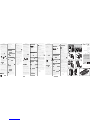 1
1
-
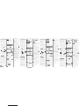 2
2


in altre lingue
- français: Nice Era P View
- español: Nice Era P View
- Deutsch: Nice Era P View
- polski: Nice Era P View
Documenti correlati
Altri documenti
-
Nice Automation One (OXI and OX2 series) Manuale del proprietario
-
-
-
-
-