
MX104 Universal Roung Plaorm
Hardware Guide
Published
2022-12-13

Juniper Networks, Inc.
1133 Innovaon Way
Sunnyvale, California 94089
USA
408-745-2000
www.juniper.net
Juniper Networks, the Juniper Networks logo, Juniper, and Junos are registered trademarks of Juniper Networks, Inc.
in the United States and other countries. All other trademarks, service marks, registered marks, or registered service
marks are the property of their respecve owners.
Juniper Networks assumes no responsibility for any inaccuracies in this document. Juniper Networks reserves the right
to change, modify, transfer, or otherwise revise this publicaon without noce.
MX104 Universal Roung Plaorm Hardware Guide
Copyright © 2022 Juniper Networks, Inc. All rights reserved.
The informaon in this document is current as of the date on the tle page.
YEAR 2000 NOTICE
Juniper Networks hardware and soware products are Year 2000 compliant. Junos OS has no known me-related
limitaons through the year 2038. However, the NTP applicaon is known to have some diculty in the year 2036.
END USER LICENSE AGREEMENT
The Juniper Networks product that is the subject of this technical documentaon consists of (or is intended for use
with) Juniper Networks soware. Use of such soware is subject to the terms and condions of the End User License
Agreement ("EULA") posted at hps://support.juniper.net/support/eula/. By downloading, installing or using such
soware, you agree to the terms and condions of that EULA.
ii

Table of Contents
About This Guide | ix
1
Overview
MX104 Universal Roung Plaorm Overview | 2
MX104 Chassis | 5
MX104 Chassis Overview | 5
MX104 Hardware and CLI Terminology Mapping | 7
MX104 Component Redundancy | 8
MX104 Alarm Contact Port Overview | 9
MX104 LEDs Overview | 11
MX104 Cooling System and Airow Overview | 14
MX104 Power System | 16
MX104 Power Overview | 16
MX104 Power Consumpon | 19
MX104 AC Power Specicaons | 20
MX104 AC Power Cord Specicaons | 21
MX104 DC Power Specicaons | 23
MX104 DC Power Cable and Lug Specicaons | 25
MX104 Host Subsystem | 26
MX104 Roung Engine Overview | 26
MX104 Interface Modules | 31
MX104 Modular Interface Card (MIC) Overview | 32
MX104 Port and Interface Numbering | 34
2
Site Planning, Preparaon, and Specicaons
Preparing the Site for the MX104 Router Overview | 43
iii

MX104 Site Guidelines and Requirements | 44
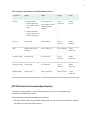
MX104 Router Physical Specicaons | 44
MX104 Router Environmental Specicaons | 45
MX104 Chassis Grounding Cable and Lug Specicaons | 47
Rack Requirements for MX104 Routers | 52
Cabinet Requirements for MX104 Routers | 53
Clearance Requirements for Airow and Hardware Maintenance on MX104 Routers | 56
MX104 Network Cable and Transceiver Planning | 57
Calculang Power Budget and Power Margin for Fiber-Opc Cables | 57
How to Calculate Power Budget for Fiber-Opc Cables | 57
How to Calculate Power Margin for Fiber-Opc Cables | 58
Fiber-Opc Cable Signal Loss, Aenuaon, and Dispersion | 60
MX104 Management and Console Port Specicaons and Pinouts | 61
MX104 Clocking and Timing Ports Overview | 62
MX104 Roung Engine Ethernet Port Specicaons | 62
MX104 Roung Engine Auxiliary and Console Ports Specicaons | 64
MX104 Roung Engine USB Port Specicaons | 66
MX104 Alarm Contact Port Specicaons | 67
MX104 BITS Port Specicaons | 70
MX104 1-PPS and 10-MHz GPS Port Specicaons | 72
MX104 Time of Day Port Specicaons | 73
3
Inial Installaon and Conguraon
MX104 Installaon Overview | 77
Unpacking the MX104 | 78
Unpacking an MX104 Router | 78
Parts Inventory (Packing List) for an MX104 Router | 79
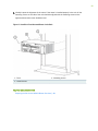
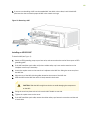
Installing the MX104 | 81
iv

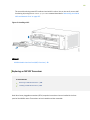
Connecng the MX104 to Power | 84
Connecng the MX104 Router to Earth Ground | 84
Connecng AC Power Cords to the MX104 Router | 86
Connecng DC Power Cables to the MX104 Router | 88
Connecng the MX104 to the Network | 94
Connecng the MX104 Router to Management Devices | 94
Connecng the Router to a Network for Out-of-Band Management | 94
Connecng the Router to a Management Console Device | 95
Connecng the MX104 Router to External Clocking and Timing Devices | 96
Connecng 1-PPS and 10-MHz Timing Devices to the MX104 Router | 97
Connecng a T1 or E1 External Clocking Device to the MX104 Router | 97
Connecng a Time-of-Day Device to the MX104 Router | 97
Connecng Interface Cables to MX104 Routers | 98
Inially Conguring the MX104 Router | 99
4
Maintaining Components
Maintaining MX104 Components | 106
Tools and Parts Required to Maintain the MX104 Components | 106
MX104 Field-Replaceable Units (FRUs) | 106
Roune Maintenance Procedures for Your Site | 107
Roune Maintenance Procedures for the MX104 Router | 108
Replacing an MX104 Console or Auxiliary Cable | 109
Removing an MX104 Console or Auxiliary Cable | 109
Installing an MX104 Console or Auxiliary Cable | 110
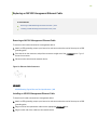
Replacing an MX104 Management Ethernet Cable | 111
Removing an MX104 Management Ethernet Cable | 111
Installing an MX104 Management Ethernet Cable | 111
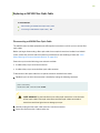
Replacing an MX104 Fiber-Opc Cable | 112
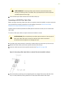
Disconnecng an MX104 Fiber-Opc Cable | 112
Connecng an MX104 Fiber-Opc Cable | 113
v

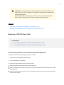
Replacing an MX104 Alarm Cable | 114
Disconnecng the Router from an External Alarm-Reporng Device | 114
Connecng the MX104 Router to an External Alarm-Reporng Device | 115
MX104 Roune Maintenance Checklist | 116
Maintaining MX104 Cooling System Components | 117
Maintaining the MX104 Cooling System | 117
Replacing an MX104 Fan Tray | 119
Removing an MX104 Fan Tray | 119
Installing an MX104 Fan Tray | 120
Maintaining the MX104 Air Filter | 121
Replacing an MX104 Air Filter | 122
Removing an MX104 Air Filter | 122
Installing an MX104 Air Filter | 124
Maintaining MX104 Host Subsystem Components | 125
Maintaining the MX104 Roung Engines | 125
Replacing an MX104 Roung Engine | 127
Eect of Taking the MX104 Roung Engine Oine | 128
Taking an MX104 Roung Engine Oine | 130
Removing an MX104 Roung Engine | 131
Installing an MX104 Roung Engine | 133
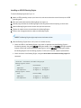
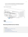
Maintaining MX104 Interface Modules | 134
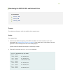
Maintaining the MX104 MICs and Network Ports | 135
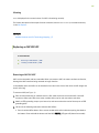
Replacing an MX104 MIC | 136
Removing an MX104 MIC | 136
Installing an MX104 MIC | 138
Replacing an MX104 Transceiver | 140
Removing an MX104 Transceiver | 141
Installing an MX104 Transceiver | 142
Maintaining Cables That Connect to MX104 Network Ports | 143
Maintaining MX104 Power System Components | 145
vi

Replacing an MX104 AC Power Supply | 145
Removing an MX104 AC Power Supply | 145
Installing an MX104 AC Power Supply | 148
Replacing an MX104 DC Power Supply | 149
Removing an MX104 DC Power Supply | 149
Installing an MX104 DC Power Supply | 153
5
Troubleshoong Hardware
Troubleshoong the MX104 | 159
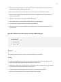
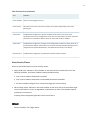
Troubleshoong Resources for MX104 Routers | 159
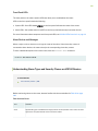
Understanding Alarm Types and Severity Classes on MX104 Routers | 160
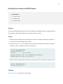
Verifying Acve Alarms on MX104 Routers | 162
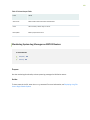
Monitoring System Log Messages on MX104 Routers | 163
6
Contacng Customer Support and Returning the Chassis or Components
Contacng Customer Support and Returning the Chassis or Components | 165
Contact Customer Support | 165
How to Return a Hardware Component to Juniper Networks, Inc. | 166
Locang the MX104 Components and Serial Numbers | 167
MX104 Chassis Serial Number Label | 168
MX104 Fan Tray Serial Number Label | 169
MX104 MIC Serial Number Label | 170
MX104 Power Supply Serial Number Label | 171
MX104 Roung Engine Serial Number Label | 172
Guidelines for Packing Hardware Components for Shipment | 172
Packing the MX104 Router for Shipment | 172
7
Safety and Compliance Informaon
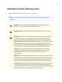
Denion of Safety Warning Levels | 176
General Safety Guidelines for Juniper Networks Devices | 178
vii

General Safety Warnings for Juniper Networks Devices | 179
Prevenng Electrostac Discharge Damage to an MX104 Router | 182
Installaon Safety Warnings for Juniper Networks Devices | 184
General Laser Safety Guidelines for Juniper Networks Devices | 190
Laser Safety Warnings for Juniper Networks Devices | 191
Maintenance and Operaonal Safety Warnings for MX104 Routers | 194
In Case of an Electrical Accident | 200
General Electrical Safety Warnings for Juniper Networks Devices | 200
General Electrical Safety Guidelines and Electrical Codes for Juniper Networks Devices | 205
MX104 AC Power Electrical Safety Guidelines and Warnings | 206
MX104 DC Power Electrical Safety Guidelines | 207
DC Power Electrical Safety Warnings for Juniper Networks Devices | 208
Site Electrical Wiring Guidelines for MX104 Routers | 212
Agency Approvals for MX104 Routers | 213
Compliance Statements for NEBS for MX104 Routers | 215
Compliance Statements for EMC Requirements for MX104 Routers | 216
Compliance Statements for Environmental Requirements | 218
Compliance Statements for Acousc Noise for MX104 Routers | 218
Statements of Volality for Juniper Network Devices | 219
viii

About This Guide
Use this guide to install hardware and perform inial soware conguraon, roune maintenance, and
troubleshoong for the MX104 Universal Roung Plaorm. Aer compleng the installaon and basic
conguraon procedures covered in this guide, refer to the Junos OS documentaon for informaon
about further soware conguraon.
RELATED DOCUMENTATION
MX104 Quick Start Guide
Junos OS for MX Series 5G Universal Roung Plaorms
ix


MX104 Universal Roung Plaorm Overview
IN THIS SECTION
Benets of MX104 Router | 2
System Overview | 3
The Juniper Networks MX104 Universal Roung Plaorm is opmized for aggregang mobile,
enterprise WAN, business, and residenal access services. The MX104 router is designed for high-
density access and pre-aggregaon and is environmentally hardened to allow outside deployments in
cabinets and remote terminals. The router is a high-performance router funconing as a universal
aggregaon plaorm for mobile broadband and metro Ethernet applicaons. It also acts as a universal
edge plaorm supporng all types of private WAN, data center interconnect, Internet edge, business
edge, and residenal edge services.
The router is powered by the Junos Trio chipset and runs the Junos® operang system (Junos OS) for
high-performance roung and switching. For a list of related Junos OS documentaon, see hps://
www.juniper.net/documentaon/soware/junos/.
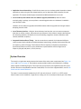
Benets of MX104 Router
•System Capacity—MX104 provides 80 Gbps of throughput. MX104 has four Modular Interface Card
(MIC) slots and supports redundant xed 10-Gigabit Ethernet interfaces for exible network
connecvity.
•The Programmable Chipset—The chipset implemented in the MX Series routers has a programmable
forwarding data structure that allows fast microcode changes in the hardware itself, and a
programmable lookup engine that allows inline service processing. the chip’s programmable QoS
engine supports coarse and ne-grained queuing to address the requirements of core, edge, and
aggregaon use cases.
•Always-on infrastructure base—MX Series routers ensure network and service availability with a
broad set of mullayered physical, logical, and protocol-level resiliency aspects. Junos OS Virtual
Chassis technology on MX Series routers supports chassis-level redundancy and enables you to
manage two routers as a single element. Mulchassis link aggregaon group (MC-LAG)
implementaon supports stateful chassis, card, and port redundancy.
2

•Applicaon-Aware Networking—On MX Series routers you can use deep packet inspecon to detect
applicaons, and by using the user-dened policies, you can determine trac treatment for each
applicaon. This feature enables highly customized and dierenated services at scale.
•Junos Connuity and Unied In-Service Soware Upgrade (Unied ISSU)—With the Junos
connuity plug-in package, you can perform a smooth upgrade when new hardware is installed in
your MX Series router.
Unied in-service soware upgrade (unied ISSU) enables soware upgrades and changes without
disrupng network trac.
•Junos Telemetry Interface—Using the Junos telemetry interface data, you can stream component-
level data to monitor, analyze, and enhance the performance of the network. Analycs derived from
this streaming telemetry can idenfy current and trending congeson, resource ulizaon, trac
volume, and buer occupancy.
•Integrated Hardware-Based Timing— You do not need to use external clocks because MX Series
routers support highly scalable and reliable hardware-based ming, including Synchronous Ethernet
for frequency, and the Precision Time Protocol (PTP) for frequency and phase synchronizaon.
Synchronous Ethernet and PTP can be combined in a hybrid mode to achieve a high level of
frequency (10 ppb) and phase (<1.5 uS) accuracy.
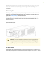
System Overview
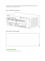
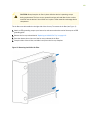
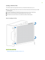
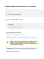
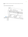
The chassis is a rigid sheet metal structure that houses all the other router components (see Figure 1 on
page 4 and Figure 2 on page 4). The hardware system provides resiliency and redundancy, including
power supplies and Roung Engines. The chassis also has four built-in 10-Gigabit Ethernet SFP+ ports
and four slots that accept Modular Interface Cards (MICs). For a list of the supported MICs, see the
MX
Series Interface Module Reference
.
The router is environmentally hardened and is 3.5 rack units (U; that is, 6.125 in., or 15.55 cm) tall.
Several routers can be stacked in a single oor-to-ceiling rack, for increased port density per unit of oor
3


MX104 Chassis
IN THIS SECTION
MX104 Chassis Overview | 5
MX104 Hardware and CLI Terminology Mapping | 7
MX104 Component Redundancy | 8
MX104 Alarm Contact Port Overview | 9
MX104 LEDs Overview | 11
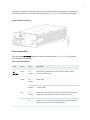
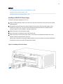
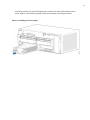
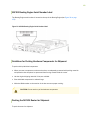
MX104 Chassis Overview
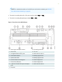
The MX104 router contains a front panel with slots in which you can install eld-replaceable units
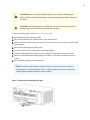
(FRUs). From the front of the chassis, you can see the following components (see Figure 3 on page 6):
• Alarm console port labeled ALARM, which accepts a DE-15 alarm cable.
• Alarm LEDs that indicate major or minor alarms.
• Built-in 10-Gigabit Ethernet MIC with four ports that accept 10-Gigabit Ethernet SFP+ transceivers.
•ONLINE/OFFLINE buon.
• Chassis status LED labeled SYS OK
• External building integrated ming system (BITS) port labeled EXT REF CLOCK
• Time-of-day (TOD) port
• External clocking ports supporng 1-PPS and 10-MHz input and output
• ESD point
• Fan tray, which contains ve fans and an air lter
• Four slots for installing MICs
5

NOTE: For a detailed descripon of the MX104 port and interface numbering see "MX104
Port and Interface Numbering" on page 34.
• Two slots for installing either AC or DC power supplies, labeled PS 0 and PS 1
• Two slots for installing Roung Engines, labeled RE 0 and RE 1
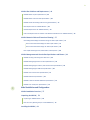
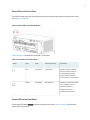
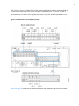
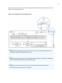
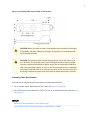
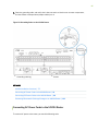
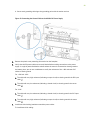
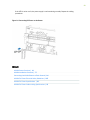
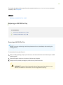
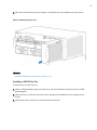
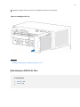
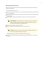
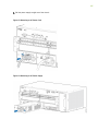
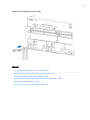
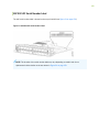
Figure 3: Front View of the MX104 Router
1—Alarm input and output contacts 10—Grounding terminals
2—Alarm LEDs 11—Fan tray
3—10-Gigabit Ethernet SFP+ ports 12—MIC slots 0/1 and 1/1
4—Online/oine buon 13—Roung Engine slot 1
5—System status LED 14—Roung Engine slot 0
6—External reference clocking port 15—Power supply slot 1
7—Time-of-day (ToD) port 16—Power supply slot 0
8—1-PPS and 10-MHz GPS input and output
ports
17—MIC slots 0/0 and 1/0
9—ESD point
6

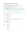
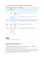
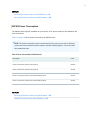
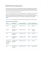
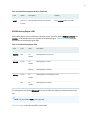
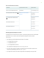
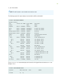
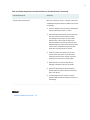
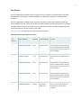
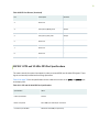
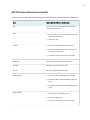
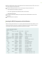
MX104 Hardware and CLI Terminology Mapping
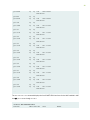
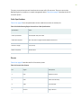
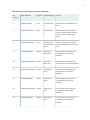
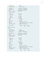
The MX104 router supports the components in Table 1 on page 7, listed in alphabec order.
Table 1: MX104 Routers Hardware Components and CLI Terminology
Component Hardware
Model
Number
CLI Name Descripon
Chassis N/A MX104 "MX104 Universal Roung Plaorm Overview" on page 2
Cooling system, including fan trays and
air lters
"MX104 Cooling System and Airow Overview" on page 14
Air lter kit FLTR-KIT-
MX104
N/A
Fan tray FANTRAY-
MX104
Fan Tray
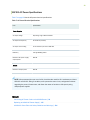
Power system components "MX104 Power Overview" on page 16
Power
blank cover
PWR-
BLANK-
MX104
N/A
Power
supply
•AC:
PWR-
MX104-
AC
•DC:
PWR-
MX104-
DC
PEM
7

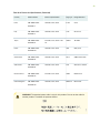
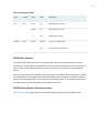
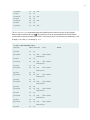
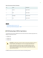
Table 1: MX104 Routers Hardware Components and CLI Terminology
(Connued)
Component Hardware
Model
Number
CLI Name Descripon
MIC N/A (built-
in)
4x
10GE(LAN)
SFP+
"MX104 Modular Interface Card (MIC) Overview" on page 32
See
MX Series Interface
Module Reference
.
"MX104 Modular Interface Card (MIC) Overview" on page 32
MPC N/A (built-
in)
FPC "MX104 Modular Interface Card (MIC) Overview" on page 32
Roung
Engine
RE-S-
MX104
Routing
Engine
"MX104 Roung Engine Overview" on page 26
Transceiver See
MX
Series
Interface
Module
Reference
.
Xcvr "MX104 Modular Interface Card (MIC) Overview" on page 32
SEE ALSO
MX104 Port and Interface Numbering | 34
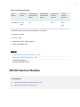
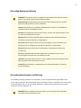
MX104 Component Redundancy
The MX104 chassis provides redundancy and resiliency. The hardware system is fully redundant,
including power supplies, Roung Engines, and cooling system.
A fully congured router is designed so that no single point of failure can cause the enre system to fail.
Only a fully congured router provides complete redundancy. All other conguraons provide paral
redundancy. The following major hardware components are redundant:
8

• Power supplies—In a redundant conguraon, the router contains either two AC or DC power
supplies that install into the front of the chassis. The slots are labeled PS 0 and PS 1 (le to right).
Each power supply provides power to all components in the router. When two power supplies are
present, they share power almost equally within a fully populated system. If one power supply in a
redundant conguraon fails or is removed, the remaining power supplies assume the enre
electrical load without interrupon. Two power supplies provide the maximum conguraon with full
power for as long as the router is operaonal.
•Roung Engine—If two Roung Engines are installed, one funcons as the primary and the other
funcons as the backup. If the primary Roung Engine fails, the backup can take over as the primary.
• Cooling system—The cooling system has redundant components, which are controlled by the host
subsystem. If one of the fans fails, the host subsystem increases the speed of the remaining fans to
provide sucient cooling for the router indenitely.
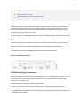
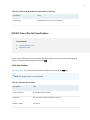
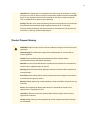
MX104 Alarm Contact Port Overview
The MX104 router has four external alarm contacts (also known as potenal free contacts) for
connecng the router to external alarm devices. The port labeled ALARM uses a 15-pin D-type
connector. The external alarm contact has 15 pins that accept a single core wire from external alarm
devices. A DE-15 alarm cable is required to connect the MX104 router to external alarm devices. Use
the gauge wire appropriate for the external device that you are connecng.
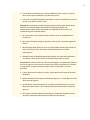
Whenever a system condion triggers an alarm, the alarm relay contacts are acvated, which in turn
acvates the external alarm devices. The alarm seng is open or closed.
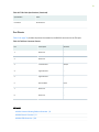
You can connect and congure two output alarms and four input alarms. Two addional output alarms
are reserved and are used to indicate major and minor system alarms. Each output and input alarm has
two contacts for connecng the router to external alarm devices. Contact 1 of each alarm can be
congured as Normally Open [NO] or Normally Closed [NC] through the CLI. Contact 2 of each alarm
funcons as a reference [REF] or negave potenal terminal for Contact 1 of the corresponding alarm
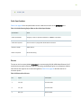
and provides a current path for external alarm devices. Table 2 on page 9 describes the funcons of
the alarm contacts.
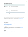
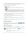
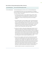
Table 2: Alarm Relay Contact Funcons
Contact Name Contact Name Funcon
Contact 1 Normally Open [NO] Current is not owing through Contact 1 and Contact 2 [REF] when
operang normally. When the current ows, the closed alarm is
generated.
9

Table 2: Alarm Relay Contact Funcons
(Connued)
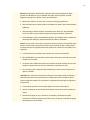
Contact Name Contact Name Funcon
Normally Closed
[NC]
Current is owing through Contact 1 and Contact 2 [REF] when
operang normally. When the current stops owing, the open alarm is
generated.
Contact 2 Reference [REF] Provides the current path for the external alarm-reporng device and
funcons as a reference or negave potenal terminal for Contact 1.
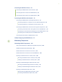
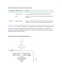
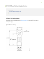
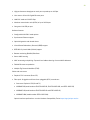
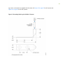
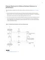
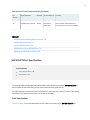
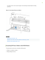
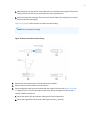
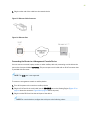
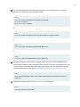
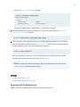
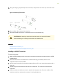
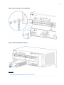
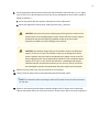
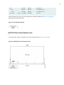
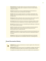
Figure 4 on page 10 shows an example of a wiring diagram for a simple output alarm-reporng device.
In this case, the device is a light bulb that illuminates when the device encounters a condion that
acvates the red alarm LED and relay contacts. The alarm relay contacts can also be used to acvate
other devices such as bells or buzzers.
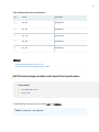
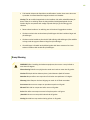
Figure 4: Sample Output Alarm-Reporng Device
10

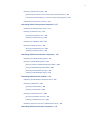
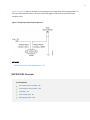
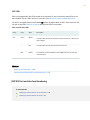
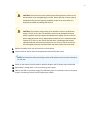
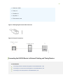
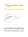
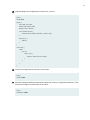
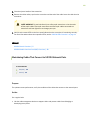
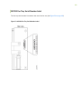
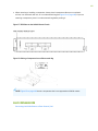
Figure 5 on page 11 shows an example of a wiring diagram for a simple input alarm-reporng device. In
this case, the push buon switch is an alarm sensor that triggers an input alarm when a door-open
condion occurs.
Figure 5: Sample Input Alarm-Reporng Device
SEE ALSO
MX104 Alarm Contact Port Specicaons | 67
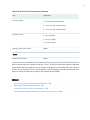
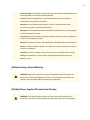
MX104 LEDs Overview
IN THIS SECTION
Alarm LEDs on the Front Panel | 12
System LED on the Front Panel | 12
MIC LEDs | 13
Power Supply LED | 13
Roung Engine LEDs | 13
11
La pagina si sta caricando...
La pagina si sta caricando...
La pagina si sta caricando...
La pagina si sta caricando...
La pagina si sta caricando...
La pagina si sta caricando...
La pagina si sta caricando...
La pagina si sta caricando...
La pagina si sta caricando...
La pagina si sta caricando...
La pagina si sta caricando...
La pagina si sta caricando...
La pagina si sta caricando...
La pagina si sta caricando...
La pagina si sta caricando...
La pagina si sta caricando...
La pagina si sta caricando...
La pagina si sta caricando...
La pagina si sta caricando...
La pagina si sta caricando...
La pagina si sta caricando...
La pagina si sta caricando...
La pagina si sta caricando...
La pagina si sta caricando...
La pagina si sta caricando...
La pagina si sta caricando...
La pagina si sta caricando...
La pagina si sta caricando...
La pagina si sta caricando...
La pagina si sta caricando...
La pagina si sta caricando...
La pagina si sta caricando...
La pagina si sta caricando...
La pagina si sta caricando...
La pagina si sta caricando...
La pagina si sta caricando...
La pagina si sta caricando...
La pagina si sta caricando...
La pagina si sta caricando...
La pagina si sta caricando...
La pagina si sta caricando...
La pagina si sta caricando...
La pagina si sta caricando...
La pagina si sta caricando...
La pagina si sta caricando...
La pagina si sta caricando...
La pagina si sta caricando...
La pagina si sta caricando...
La pagina si sta caricando...
La pagina si sta caricando...
La pagina si sta caricando...
La pagina si sta caricando...
La pagina si sta caricando...
La pagina si sta caricando...
La pagina si sta caricando...
La pagina si sta caricando...
La pagina si sta caricando...
La pagina si sta caricando...
La pagina si sta caricando...
La pagina si sta caricando...
La pagina si sta caricando...
La pagina si sta caricando...
La pagina si sta caricando...
La pagina si sta caricando...
La pagina si sta caricando...
La pagina si sta caricando...
La pagina si sta caricando...
La pagina si sta caricando...
La pagina si sta caricando...
La pagina si sta caricando...
La pagina si sta caricando...
La pagina si sta caricando...
La pagina si sta caricando...
La pagina si sta caricando...
La pagina si sta caricando...
La pagina si sta caricando...
La pagina si sta caricando...
La pagina si sta caricando...
La pagina si sta caricando...
La pagina si sta caricando...
La pagina si sta caricando...
La pagina si sta caricando...
La pagina si sta caricando...
La pagina si sta caricando...
La pagina si sta caricando...
La pagina si sta caricando...
La pagina si sta caricando...
La pagina si sta caricando...
La pagina si sta caricando...
La pagina si sta caricando...
La pagina si sta caricando...
La pagina si sta caricando...
La pagina si sta caricando...
La pagina si sta caricando...
La pagina si sta caricando...
La pagina si sta caricando...
La pagina si sta caricando...
La pagina si sta caricando...
La pagina si sta caricando...
La pagina si sta caricando...
La pagina si sta caricando...
La pagina si sta caricando...
La pagina si sta caricando...
La pagina si sta caricando...
La pagina si sta caricando...
La pagina si sta caricando...
La pagina si sta caricando...
La pagina si sta caricando...
La pagina si sta caricando...
La pagina si sta caricando...
La pagina si sta caricando...
La pagina si sta caricando...
La pagina si sta caricando...
La pagina si sta caricando...
La pagina si sta caricando...
La pagina si sta caricando...
La pagina si sta caricando...
La pagina si sta caricando...
La pagina si sta caricando...
La pagina si sta caricando...
La pagina si sta caricando...
La pagina si sta caricando...
La pagina si sta caricando...
La pagina si sta caricando...
La pagina si sta caricando...
La pagina si sta caricando...
La pagina si sta caricando...
La pagina si sta caricando...
La pagina si sta caricando...
La pagina si sta caricando...
La pagina si sta caricando...
La pagina si sta caricando...
La pagina si sta caricando...
La pagina si sta caricando...
La pagina si sta caricando...
La pagina si sta caricando...
La pagina si sta caricando...
La pagina si sta caricando...
La pagina si sta caricando...
La pagina si sta caricando...
La pagina si sta caricando...
La pagina si sta caricando...
La pagina si sta caricando...
La pagina si sta caricando...
La pagina si sta caricando...
La pagina si sta caricando...
La pagina si sta caricando...
La pagina si sta caricando...
La pagina si sta caricando...
La pagina si sta caricando...
La pagina si sta caricando...
La pagina si sta caricando...
La pagina si sta caricando...
La pagina si sta caricando...
La pagina si sta caricando...
La pagina si sta caricando...
La pagina si sta caricando...
La pagina si sta caricando...
La pagina si sta caricando...
La pagina si sta caricando...
La pagina si sta caricando...
La pagina si sta caricando...
La pagina si sta caricando...
La pagina si sta caricando...
La pagina si sta caricando...
La pagina si sta caricando...
La pagina si sta caricando...
La pagina si sta caricando...
La pagina si sta caricando...
La pagina si sta caricando...
La pagina si sta caricando...
La pagina si sta caricando...
La pagina si sta caricando...
La pagina si sta caricando...
La pagina si sta caricando...
La pagina si sta caricando...
La pagina si sta caricando...
La pagina si sta caricando...
La pagina si sta caricando...
La pagina si sta caricando...
La pagina si sta caricando...
La pagina si sta caricando...
La pagina si sta caricando...
La pagina si sta caricando...
La pagina si sta caricando...
La pagina si sta caricando...
La pagina si sta caricando...
La pagina si sta caricando...
La pagina si sta caricando...
La pagina si sta caricando...
La pagina si sta caricando...
La pagina si sta caricando...
La pagina si sta caricando...
La pagina si sta caricando...
La pagina si sta caricando...
La pagina si sta caricando...
La pagina si sta caricando...
La pagina si sta caricando...
La pagina si sta caricando...
La pagina si sta caricando...
La pagina si sta caricando...
La pagina si sta caricando...
La pagina si sta caricando...
La pagina si sta caricando...
La pagina si sta caricando...
La pagina si sta caricando...
La pagina si sta caricando...
La pagina si sta caricando...
La pagina si sta caricando...
La pagina si sta caricando...
La pagina si sta caricando...
-
 1
1
-
 2
2
-
 3
3
-
 4
4
-
 5
5
-
 6
6
-
 7
7
-
 8
8
-
 9
9
-
 10
10
-
 11
11
-
 12
12
-
 13
13
-
 14
14
-
 15
15
-
 16
16
-
 17
17
-
 18
18
-
 19
19
-
 20
20
-
 21
21
-
 22
22
-
 23
23
-
 24
24
-
 25
25
-
 26
26
-
 27
27
-
 28
28
-
 29
29
-
 30
30
-
 31
31
-
 32
32
-
 33
33
-
 34
34
-
 35
35
-
 36
36
-
 37
37
-
 38
38
-
 39
39
-
 40
40
-
 41
41
-
 42
42
-
 43
43
-
 44
44
-
 45
45
-
 46
46
-
 47
47
-
 48
48
-
 49
49
-
 50
50
-
 51
51
-
 52
52
-
 53
53
-
 54
54
-
 55
55
-
 56
56
-
 57
57
-
 58
58
-
 59
59
-
 60
60
-
 61
61
-
 62
62
-
 63
63
-
 64
64
-
 65
65
-
 66
66
-
 67
67
-
 68
68
-
 69
69
-
 70
70
-
 71
71
-
 72
72
-
 73
73
-
 74
74
-
 75
75
-
 76
76
-
 77
77
-
 78
78
-
 79
79
-
 80
80
-
 81
81
-
 82
82
-
 83
83
-
 84
84
-
 85
85
-
 86
86
-
 87
87
-
 88
88
-
 89
89
-
 90
90
-
 91
91
-
 92
92
-
 93
93
-
 94
94
-
 95
95
-
 96
96
-
 97
97
-
 98
98
-
 99
99
-
 100
100
-
 101
101
-
 102
102
-
 103
103
-
 104
104
-
 105
105
-
 106
106
-
 107
107
-
 108
108
-
 109
109
-
 110
110
-
 111
111
-
 112
112
-
 113
113
-
 114
114
-
 115
115
-
 116
116
-
 117
117
-
 118
118
-
 119
119
-
 120
120
-
 121
121
-
 122
122
-
 123
123
-
 124
124
-
 125
125
-
 126
126
-
 127
127
-
 128
128
-
 129
129
-
 130
130
-
 131
131
-
 132
132
-
 133
133
-
 134
134
-
 135
135
-
 136
136
-
 137
137
-
 138
138
-
 139
139
-
 140
140
-
 141
141
-
 142
142
-
 143
143
-
 144
144
-
 145
145
-
 146
146
-
 147
147
-
 148
148
-
 149
149
-
 150
150
-
 151
151
-
 152
152
-
 153
153
-
 154
154
-
 155
155
-
 156
156
-
 157
157
-
 158
158
-
 159
159
-
 160
160
-
 161
161
-
 162
162
-
 163
163
-
 164
164
-
 165
165
-
 166
166
-
 167
167
-
 168
168
-
 169
169
-
 170
170
-
 171
171
-
 172
172
-
 173
173
-
 174
174
-
 175
175
-
 176
176
-
 177
177
-
 178
178
-
 179
179
-
 180
180
-
 181
181
-
 182
182
-
 183
183
-
 184
184
-
 185
185
-
 186
186
-
 187
187
-
 188
188
-
 189
189
-
 190
190
-
 191
191
-
 192
192
-
 193
193
-
 194
194
-
 195
195
-
 196
196
-
 197
197
-
 198
198
-
 199
199
-
 200
200
-
 201
201
-
 202
202
-
 203
203
-
 204
204
-
 205
205
-
 206
206
-
 207
207
-
 208
208
-
 209
209
-
 210
210
-
 211
211
-
 212
212
-
 213
213
-
 214
214
-
 215
215
-
 216
216
-
 217
217
-
 218
218
-
 219
219
-
 220
220
-
 221
221
-
 222
222
-
 223
223
-
 224
224
-
 225
225
-
 226
226
-
 227
227
-
 228
228
-
 229
229
-
 230
230
-
 231
231


in altre lingue
- English: Juniper MX104
Documenti correlati
-
Juniper MX10003 Manuale utente
-
-
-
Juniper MX204 Manuale utente
-
-
-
-
-
Juniper PTX1000 Manuale utente
-