Juniper Internet Router M160 Manuale utente
- Tipo
- Manuale utente

M160 Inter net Router
Hardware Guide
Juniper Networks®, Inc.
1194 North Mathilda Avenue
Sunnyvale, California
94089
USA
408-745-2000
www.juniper.net
Part N umber: 530-007250-01, Revision 5

This product includes the En voy SNMP Eng ine, developed by Epilogue Technol ogy, an Integrated Systems Co mpany. Copyright
© 1986- 1997, Epilogue Technology Corporation. A ll rights reserved. This program and its documentation were developed
at p rivate expense, and no part of them is in the public domain.
This product includes mem ory allocation software developed by Mark Moraes, co pyright © 198 8, 1989, 1993, University of Toronto.
This product includ e s FreeBSD s oftware developed by the Un iversity of California, Ber keley, and its contributors. All of the docum entation and
software included in the 4.4BSD and 4.4BSD -Lite Releases is co pyrigh ted by the Regents of t he U niversity of California. Copyright © 1979, 1980,
1983, 1986, 1988, 1989, 1991, 1992, 1993, 1994. The Regents of the University of California. A ll rights reserved.
GateD software copyri ght © 1995, the Regents of the Unive rsity. A ll rights reserved. Gate Daemon wa s origina ted and developed through release
3.0 by Corne ll University an d its collaborators. Gated is based on Kirton’s EGP, UC Berkeley’s routing daemon (routed), and DCN’s HELLO routing
protocol. Development of Gat ed has been supported in part by t he National Science Foundation . Portions of the G ateD software copyr ight © 1988,
Regents of the University of California. All ri ghts reserved. Portions of th e GateD software copyright © 1991, D. L. S. A ssociates.
This product includes soft ware developed by Maker Communicat ions, Inc., Copyright © 1996, 19 97, Maker Commu nic ations, Inc.
Juniper Ne tworks, the Juniper Ne tworks logo, NetS creen, N etS creen Technologies, the NetScreen logo, NetScreen-Global Pro, ScreenO S, and
GigaScreen are registered tradem ark s of Juniper Networks, Inc. in the United States and ot her countries.
The following are trademarks of Juniper Networks, Inc.: ERX, ESP, E-series, Instant Virtual Extranet, Internet Processor, J2300, J4300, J6300, J-Protect,
J-series,J-Web,JUNOS,JUNOScope,JUNOScript,JUNOSe,M5,M7i,M10,M10i,M20,M40,M40e,M160,M320,M-series,MMD,NetScreen-5GT,
NetScreen-5XP, NetScreen- 5X T, NetScreen-25, NetScreen-50, NetS creen-204, N etS creen-208, NetScreen-500, NetScreen-520 0, Net Screen-54 00,
NetScreen-IDP 10, NetScreen-IDP 100, NetScreen-IDP 5 00, NetScreen-Remote Security Clie nt, NetScreen-Remote VPN Client, NetScreen-SA 100 0 Series,
NetScreen-SA 3000 Ser ies, NetScreen-SA 5000 Se ries, NetScreen-SA Central Manag er, NetScreen Secure Access, NetScreen-SM 300 0, NetScreen-Security
Manag er, NMC-RX, SDX, Stateful Signature, T 320, T640, T-series, and TX Mat rix . All other trademarks, serv ice marks, registered trademarks, or
registered service m arks are the property of their respective owners. All specificatio ns are subject to change withou t notice.
Junip er Networks assu mes no resp onsibility for any in a c c urac ies in this docume nt. Junip er Networks reserves the right to
change, modify, transfer, or otherwise revise this p ubli c atio n without notice.
Copyright © 2005, Juniper Ne t works, Inc. All rights reserved.
M160 Internet Router Hardware Guide
Copyright © 2005, Juniper Networks, Inc.
All rights reserved. Printed in U SA.
Writing: Sheila Nolte, Tony Mauro, Jerry Isaac
Editing: Stella Hackell
Illustration: Faith Bradford
Cover Design: Edmonds Design
Revision History
25 February 2005—530- 007250-01 Revision 5. Correct DC power illustratio n and replacement procedure.
12 November 2004— 530-007250-01 Revision 4. Revised fuse replaceme nt procedure.
30 June 2003—5 30-007250-01 Revision 3. Cor rec ted and added com ponent information.
15 Octob e r 2002—530-007250-01 Revision 2. Inc orporated up dated tech nic al information; synchronized with M 40e Inte rnet Router Ha rdware Guid e.
15 March 20 02—530-007250-01 Revi sio n 1. In c orporated update d technic a l information.
15 October 2001—Incorporated updated technical information.
15 May 2001—Adopte d ne w templa te.
28 February 2001—Incor porated updated tech nic al information.
31 August 2000 —Incor porated updated te c hnical informati on.
31 March 2000—First edition .
The information in this document is current as of the d a te list ed in the revision history.
Juniper Networks assumes n o responsibility for any inaccuracies in this documen t. Juniper Networks reserves th e right to ch ange, modify, transfer or
otherwise revise this publica tion w ith out notice.
Products made or sold by Juni per Networ ks (includ ing the ERX-310, ERX-705, ERX-710, ERX-1410, ERX-1440, M5, M7i, M10, M10i, M20, M40, M40e,
M160 , M320, and T320 routers, T640 routing n ode, and the J UNOS and SDX-30 0 software) or comp onents th ereof m ight be c overed by one or more of the
following patents that are owned by or licensed to Juniper Networ ks : U.S. Patent Nos. 5 ,473,599, 5,90 5 ,725, 5 ,909,440, 6,19 2 ,051, 6,3 33,650, 6,359,479,
6,406,312, 6,429,706, 6,459,579, 6,493,34 7, 6,538, 518, 6,538,899 , 6,552,918, 6,56 7,902, 6,578,186, and 6,590,785.
YEAR 2000 NOTICE
Juniper N etwor ks h ardware and sof tware products are Year 2000 compliant. The JUNOS s oftware has no known tim e-related limitations through the year
2038. However, the NTP application is known to have some difficulty in the ye ar 2036 .
ii

End User License Agreement
READ THIS END USER LICENSE AGREEMENT ("AGREEMENT") BEFORE DOWNLOADING, INSTALLING, OR USING THE SOFTWARE. BY DOWNLOADING,
INSTALLING, OR USING THE SOFTWARE OR OTHERWISE EXPRESSING YOUR AGREEMENT TO THE TERMS CONTAINED HEREIN, YOU (AS CUSTOMER
OR IF YOU ARE NOT THE CUSTOMER, AS A REPRESENTATIVE/AGENT AUTHORIZED TO BIND THE CUSTOMER) CONSENT TO B E BOUND BY THIS
AGREEMENT. IF YOU DO NOT OR CANNOT AGREE TO THE T ERMS CONTAINED HEREIN, THEN (A) D O NOT DOWNLOAD, INSTALL, OR USE THE
SOFTWARE, AND (B) YOU MAY CONTACT JUNIPER NETWORKS REGARDING LICENSE TERMS.
1. The Parties. T he parties to this Agreement are Jun iper N e t works, In c. and its su bsidiaries (collectively "Jun iper "), and th e person or organization that
originally purchased f rom Jun iper or an authorized Juniper reseller the app licab le licen s e(s) for use of t he Software ("Customer") (collectively, the "Parties").
2. The Software. In this A greem ent, "Software" m eans the program mod ules and features of the Juniper or Junip er-s upplied software, and updates a nd
releases of such software, for which Cu s tomer has paid the applicable licen se or suppor t fees to Junip er or an autho rized Jun iper reseller.
3. License Grant. Subje ct to paymen t of the applicable fees and the lim itations and restrictions set forth herein, Juniper grants to C ustom er a
non-exclusive and non-tran sferable lic ense, w ithout right to sublicense, to use the Soft ware, in executable form only, subject to the following use restrictions:
a. Customer sh all use the Software solely as emb edd e d in, and for execution on, Juniper equipm ent origi nally p urchased by C ustomer from
Junipe r or an authorized Jun iper res eller, un les s the applica ble Juniper documen tation expressly p er mits installation on non-Juniper equipment.
b. Customer shall use the Software on a single hardware chassis having a single processing unit, or as many chassis or processing
units for which Customer has paid th e applic able license fees.
c. Other Ju nip er documen tation for the Software (such as product purchase documents, docu me nts accompanying the product, the
Software user man ual(s), Ju nip er ’s website for t he So ft ware, or messages displayed by the So ftware) may specify limits to Custom er ’s use of the
Software. Such limits may restrict use to a m aximum number of seats, concurrent users, ses sio ns, subscribers, nodes, or t ransactions, or
require th e purchase of sepa rate licenses to u s e particular features, funct ion alities, o r capabilities, or provide tem poral or geographical l imits.
Customer’s u se of the Software shall be subject to all such limitations and purchase of all applicable licenses.
The foregoing license is not transferable or assignab le by Customer. N o license is granted herein to any user who did not originally purchase
the applicable license(s) for the Sof tware from Juniper or an authorized Juniper reseller.
4. Use Prohibitions. N otwithstanding th e foregoing, the license provided herein does not permit the Customer to, and Customer agrees n ot to and shall
not: (a) modify, un bundle, reverse e ngin eer, or create derivative works based on the Software; (b) make unau th orized copies of the Software (except as
necessary for backup purposes); (c) rent, transfer, or grant any rights in and to any copy of the So ft ware, in any form, to any third party; (d) remove any
proprietary noti ces, labels, or marks on or in a ny copy of the Software; (e) distribute any copy of the Softwa re to any third party, including as may be
embedded in Juniper equipment sold in the seco ndhand market; (f) use any ’locked’ or key-restricted feature, function , or capability without first purchasing
the appl icable license(s) and obtaining a valid key f rom Juniper, even if such feature, function, or ca pability is enab led without a key; (g) distrib ute any key
for the Software provided by Juniper to any third party; (h) use t he So ftware in a ny manner th at extends or is broader than the uses purchased by Cu stomer
from Juniper o r an authorized Juniper reseller; (i) use the So ftware on n on-Juniper equipmen t w here the Ju nip er documentation does not expressly permit
installation on non-Jun iper equipm ent; (j) use th e Soft ware (or make it available for use) on Juniper equipment that the C us tomer did not or iginally purchase
from Juniper or an author ized J uniper reseller; or (k) use the Soft ware in any manner other than as expressly provided herein.
5. Audit. C ustomer shall maintain accurate records as n ecessar y to verify com pliance with this Agreem ent . Upon request by Juniper, Customer s hal l
furnish such records to Juniper and certify its com pliance with t his Agreemen t.
6. Confidentiality. The Parties agree tha t aspects of the Software a nd associated documentation are the confidential property of Juniper. As such,
Customer shall exercise all reasonable comm ercial efforts to maintain the Software and associated documentation in confidence, which at a minimum
includes restricting access to the S oftware to Cu stomer employees and co ntractors h aving a need to use the Sof tware.
7. Ownership. Juniper and Juniper’s licensors, respectively, retain ownership of a ll right, title, and interest (in cluding copyright) in and to the Software,
associated documentation, a nd all copies of th e Software. N ot hing in this A greem ent constitu tes a transfer or conveyance of any ri ght , title, or interest in
the So ftware or associ ated documentation, or a sa le of t he Software, associated docu mentation, or copies of the Software.
8. Warranty, Limitation of Liability, Disclaimer of Warranty. If the Soft ware is dist ributed on physical media (such as CD), Ju niper warrants for 9 0 days
from delivery that th e media on which th e Software is delivered will be free of defects in material and workm a nsh ip under normal use. This limi ted
warranty extends only to the Custom er. Except as may be expressly provided in separate documentation from Junip er, no oth er warranties a ppl y to
the Software, and the Software is otherwise provided AS IS. Customer assumes all risks arising from use of the Software. Customer’s sole remedy and
Junip er’s ent ire liability under t his limited warranty is that Juniper, at its option, will repair or replace the media containing the Software, or provide a
refund, provided that Customer makes a proper warranty claim to Juniper, in writ ing, within the warranty per iod. Nothing in this A greem ent shall give rise
to any obligat ion to support the Software. Any such s upport shall be g overned by a separate, written agreemen t. To th e maximu m extent pe rm itt ed by law,
Junipe r s hall not be liable for any liability for lost profits, loss of da ta or cos ts or procurem ent of substit ute goods or se rv ices, or for any sp e cial, indirect, or
consequ ent ial damages arising out of this Ag reem ent, the Software, or any Juniper or Junip er- su pplied soft ware. In no event shall Juniper be liable for
dama ges arising from unautho rized or improper use of any Jun iper or Juniper-su pplied software.
EXCEPT AS EXPRESSLY PROVIDED H EREIN OR IN SEPARATE DOCUM E NTATIO N PROVIDE D FROM JUN IPER AND TO THE EXTENT PERMITTE D BY
LAW, JUNIPER DISCLAIMS ANY AND ALL WARRANTIES IN AND TO THE SOFTWARE (WHETHER EXPRESS, IMPLIED, STATUTORY, OR OTHERWISE),
INCLUDING ANY IMP LIED WARRANTY OF M ERCHA NTABILITY, FITNESS FOR A PARTICULAR PURPOSE, OR NON INFRINGE MENT. IN NO EVENT DOES
iii

JUNIPER WARRANT THAT THE SOFTWARE, OR ANY EQUIPMENT OR NETWORK RUNNING THE SO FTWARE, WILL OPERATE WITHOUT E RROR OR
INTERRUPTION, OR WILL BE FREE OF VULNERABILITY TO INTRUSION OR ATTACK.
9. Terminat ion. Any breach of this Agreement or failure by Customer to pay any app licable fees due sha ll result in automatic term inat ion of t he
license granted herein . Upon such term in a tio n, Customer shall destroy or return to J uniper all copies of the Software and related documentation in
Customer’s possession or control.
10. Taxes. All license fees for the Software are exclusive of taxes, w it hholdings, duties, or levies (collectively "Ta xes"). Customer shall be responsible
for paying Taxes arising from the purchase of the license, or importation or use of the Software.
11. Export. C ustomer agrees to comply wit h a ll ap plicable export laws and restrictions and regulat ions of any United States and any applicable foreign
agency or authority, and not to export or re-expo rt t he Software o r any direct prod uct thereof in violation of any such restrictions, laws or regulations, or
without all necessary approvals. Customer s hall be liable for any su c h violations. The version of the Software supplied to you m ay contain encryp tion or
other capabiliti e s restricting your ability to export the Software without an export license.
12. Commercial C omputer Software. The Software is "commercial co mputer software" and is provided w ith restricted rights. Use, du plic ation, or
disclos ure by the United States government is subject to restrictions set forth in this Agreement and as provided in D FARS 227.7201 through 227.72 02-4,
FAR 12.212, FAR 27.405( b)(2), FAR 52.2 27-19, or FAR 52.227 -14(ALT III) a s applicable.
13. Miscellaneo us. This A greem ent shall be governed by the laws of the State of California without reference to its conflicts of laws principles. For any
disputes ar isin g under th is Agreement, the Parties hereby consent to the personal and exclusive jurisdiction of, a nd venue in, the state and federal courts
within Santa Clara County, California. This Agreem ent constitu tes the entire an d sole agreement between Juniper and the Customer wi th respect to the
Software, and supersedes all prior and contemporaneous agreements relating to the Software, whether oral or wr itten (including any inconsistent terms
contained in a purchase order), except th at the term s of a separate written agreement executed by an authorized Juniper representative an d Customer
shall g overn to the extent such terms a re inconsistent or conflict w ith terms contained herein. No modification to this Agreement nor a ny wa iver o f any
rights hereund er s hall be effective u nless expressly assent ed to in writing by the p ar ty to b e ch a rged. If any portion of this Agreement is held invalid,the
Parties agree that such invalidity shall no t affect th e validity of the remainder of thi s Agreement.
If you have any questions about this agreement, co ntact Juniper Networks at the following address:
Juniper Ne tworks, Inc.
11 9 4 N o r t h M a t h i ld a Ave n u e
Sunnyvale, CA 94089
USA
Attn: Contracts Administrator
iv

Table of Contents
About This Guide
xix
Objectives ...........................................................................xix
Audience.............................................................................xix
Documentation Conventions ......................................................xix
List of Technical Publications......................................................xxi
Documentation Feedback........................................................ xxiii
Requesting Support...............................................................xxiii
Part 1
Product Overview
Chapter 1 System Overview .. 3
System Description...................................................................3
Field-Replaceable Units (FRUs) ......................................................4
System Redundancy..................................................................4
Safety Requirements, Warnings, and Guidelines...................................5
Chapter 2
Hardware Component Overview.. 7
Chassis.................................................................................7
Packet Forwarding Engine ..........................................................11
Midplane........................................................................ 12
Physical Interface Cards (PICs)................................................ 13
PIC Components ..........................................................14
Flexible PIC Concentrators (FPCs) ............................................ 14
FPC Components.......................................................... 16
FPC Types.................................................................. 17
Packet Forwarding Engine Clock Generators (PCGs) ........................ 18
PCG Components ......................................................... 19
Switching and Forwarding Module (SFM) .................................... 19
SFM Components ......................................................... 20
Host Module......................................................................... 22
Routing Engine................................................................. 23
Routing Engine Components............................................. 24
Miscellaneous Control Subsystem (MCS)..................................... 25
MCS Components ......................................................... 26
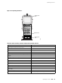
Craft Interface.......................................................................27
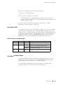
Alarm LEDs and Alarm Cutoff/Lamp Test Button............................ 28
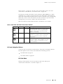
LCD and Navigation Buttons..................................................29
LCD Idle Mode............................................................. 29
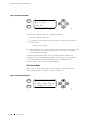
LCD Alarm Mode.......................................................... 30
Table of Contents v

M160 Internet Router Hardware Guide
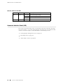
Host Module LEDs ............................................................. 31
FPC LEDs and Offline Button ................................................. 31
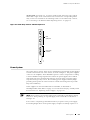
Connector Interface Panel (CIP) ................................................... 32
Routing Engine Management Ports........................................... 33
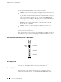
BITS Input Ports................................................................ 34
Alarm Relay Contacts.......................................................... 34
Power System ....................................................................... 35
Power Supply................................................................... 36
Circuit Breaker Box ............................................................ 38
Fuses............................................................................ 39
Cooling System ..................................................................... 39
Cooling System Components ................................................. 40
Airflow through the Chassis................................................... 40
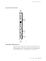
Cable Management System........................................................ 41
Chapter 3
JUNOS Internet Software Overview .. 43
Routing Engine Software Components............................................ 43
Routing Protocol Process...................................................... 44
IPv4 Routing Protocols.................................................... 44
IPv6 Routing Protocols.................................................... 46
Routing and Forwarding Tables .......................................... 47
Routing Policy ............................................................. 47
VPNs ............................................................................ 48
Interface Process............................................................... 49
Chassis Process ................................................................ 49
SNMP and MIB II Processes ................................................... 49
Management Process.......................................................... 49
Routing Engine Kernel......................................................... 49
Tools for Accessing and Configuring the Software ............................... 50
Tools for Monitoring the Software................................................. 50
Software Upgrades.................................................................. 50
Chapter 4
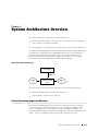
System Architecture Overview .. 51
Packet Forwarding Engine Architecture........................................... 51
Data Flow through the Packet Forwarding Engine .......................... 52
Routing Engine Architecture ....................................................... 53
Routing Engine Functions.....................................................54
Part 2
Initial Installation
Chapter 5 Preparing for Router Installation .. 59
Rack Requirements................................................................. 59
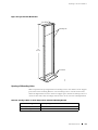
Rack Size and Strength ........................................................60
Spacing of Mounting Holes.................................................... 61
Connection to Building Structure............................................. 62
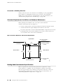
Clearance Requirements for Airflow and Hardware Maintenance..............62
Routing Node Environmental Specifications .....................................62
Fire Safety Requirements .......................................................... 63
vi Table of Contents

Table of Contents
Fire Suppression ............................................................... 63
Fire Suppression Equipment.................................................. 64
Power Guidelines, Requirements, and Specifications............................ 64
Site Electrical Wiring Guidelines.............................................. 65
Distance Limitations for Signaling ....................................... 65
Radio Frequency Interference............................................ 65
Electromagnetic Compatibility...........................................65
Router Power Requirements .................................................. 65
Chassis Grounding ............................................................. 67
Power, Connection, and Cable Specifications................................ 67
Network Cable Specifications and Guidelines.................................... 70
Fiber Optic and Network Cable Specifications .............................. 71
Signal Loss in Multimode and Single-Mode Fiber-Optic Cable ............. 71
Attenuation and Dispersion in Fiber-Optic Cable ........................... 71
Calculating Power Budget for Fiber-Optic Cable............................. 72
Calculating Power Margin for Fiber-Optic Cable............................. 73
Attenuating to Prevent Saturation at SONET/SDH PICs..................... 74
Routing Engine Interface Cable and Wire Specifications ........................ 74
Site Preparation Checklist.......................................................... 75
Chapter 6
Unpacking the Router .. 77
Tools and Parts Required........................................................... 77
Unpacking the Router .............................................................. 77
Chapter 7
Installing the Router Using a Mechanical Lift.. 81
Tools and Parts Required .......................................................... 81
Installing the Chassis Using a Mechanical Lift.................................... 81
Chapter 8
Installing the Router wit hout a Mechanical Lift .. 83
Tools and Parts Required ..........................................................84
Removing Components from the Chassis ........................................ 84
Removing the Power Supplies ................................................ 86
Removing the Rear Component Cover....................................... 86
Removing the SFMs............................................................87
Removing the MCSs ........................................................... 88
Removing the PCGs............................................................ 89
Removing the Routing Engines ............................................... 90
Removing the Rear Upper Impeller Assembly............................... 91
Removing the Rear Lower Impeller Assembly............................... 92
Removing the Fan Tray........................................................ 93
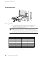
Removing the FPCs ............................................................ 94
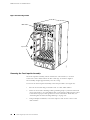
Removing the Front Impeller Assembly ..................................... 96
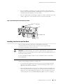
Installing the Chassis into the Rack ............................................... 97
Reinstalling Components into the Chassis........................................ 99
Reinstalling the Front Impeller Assembly...................................100
Reinstalling the FPCs ......................................................... 101
Reinstalling the Fan Tray .....................................................102
Reinstalling the Rear Lower Impeller Assembly ............................103
Reinstalling the Rear Upper Impeller Assembly............................104
Reinstalling the Routing Engines ............................................105
Reinstalling the PCGs .........................................................106
Reinstalling the MCSs......................................................... 107
Table of Contents vii

M160 Internet Router Hardware Guide
Reinstalling the SFMs .........................................................108
Reinstalling the Rear Component Cover ....................................109
Reinstalling the Power Supplies..............................................109
Chapter
9
Connecting the Router and Performing Initial Configuration .. 111
Tools and Parts Required.......................................................... 111
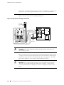
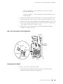
Connecting the Router to Management and Alarm Devices ................... 112
Connecting to a Network for Out-of-Band Management................... 114
Connecting to a Management Console or Auxiliary Device ............... 114
Connecting to an External Alarm-Reporting Device ....................... 115
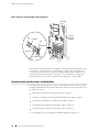
Connecting PIC Cables ............................................................ 115
Providing Power to the Router.................................................... 117
Connecting Power to the Router.............................................117
Powering On the Router...................................................... 119
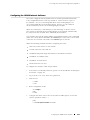
Configuring the JUNOS Internet Software .......................................121
Part 3
Hardware Maintenance, Replacement, and Troubleshooting
Procedures
Chapter 10 Maintaining Hardware Components .. 127
Routine Maintenance Procedures ................................................127
Maintaining Cooling System Components.......................................127
Maintaining the Air Filter.....................................................128
Removing the Air Filter ..................................................128
Cleaning the Air Filter ...................................................129
Installing the Air Filter...................................................129
Maintaining the Fan Tray and Impellers ....................................130
Maintaining Host Module Components ..........................................131
Maintaining Packet Forwarding Engine Components...........................132
Maintaining FPCs .............................................................133
Maintaining PICs and PIC Cables............................................134
Maintaining the PCGs.........................................................135
Maintaining SFMs.............................................................136
Maintaining Power Supplies ......................................................137
Chapter 11
Replacing Hardware Components.. 139
Tools and Parts Required..........................................................139
Replacing the CIP and Routing Engine Interface Port Cables ..................141
Removing the CIP.............................................................141
Installing the CIP ..............................................................143
Replacing Connections to Routing Engine Interface Ports.................145
Replacing the Management Ethernet Cable............................146
Replacing the Console or Auxiliary Cable ..............................146
Replace Alarm Relay Wires..............................................147
Replacing Cooling System Components .........................................148
Replacing the Fan Tray .......................................................148
viii Table of Contents

Table of Contents
Removing the Fan Tray ..................................................148
Installing the Fan Tray ...................................................149
Replacing the Front Impeller Assembly.....................................150
Removing the Front Impeller Assembly................................151
Removing the Craft Interface from the Front Impeller Assembly ....152
Installing the Craft Interface on the Front Impeller Assembly........153
Installing the Front Impeller Assembly.................................154
Replacing the Rear Lower Impeller Assembly ..............................154
Removing the Rear Lower Impeller Assembly.........................155
Installing the Rear Lower Impeller Assembly..........................155
Replacing the Rear Upper Impeller Assembly ..............................156
Removing the Rear Upper Impeller Assembly.........................157
Installing the Rear Upper Impeller Assembly ..........................158
Replacing Host Module Components ............................................159
Replacing an MCS.............................................................159
Removing an MCS........................................................159
Installing an MCS.........................................................161
Removing and Insert the PC Card ...........................................163
Removing the PC Card...................................................163
Insert the PC Card........................................................164
Replacing a Routing Engine..................................................165
Removing a Routing Engine.............................................165
Installing a Routing Engine..............................................168
Replacing Packet Forwarding Engine Components .............................169
Replacing an FPC .............................................................169
Removing an FPC ........................................................170
Installing an FPC .........................................................172
Replacing a PCG...............................................................176
Removing a PCG .........................................................176
Installing a PCG...........................................................178
Replacing a PIC ...............................................................179
Removing a PIC ..........................................................179
Installing a PIC ...........................................................181
Replace PIC Cables ...........................................................185
Removing a PIC Cable ...................................................185
Installing a PIC Cable ....................................................186
Replacing an SFM.............................................................188
Removing an SFM........................................................188
Installing an SFM.........................................................189
Replace an SFP................................................................190
Removing an SFP ........................................................190
Installing an SFP..........................................................191
Replacing Power System Components...........................................193
Replacing the Circuit Breaker Box...........................................193
Removing the Circuit Breaker Box......................................193
Installing the Circuit Breaker Box.......................................195
Replacing a Power Supply....................................................197
Removing a Power Supply...............................................197
Installing a Power Supply................................................199
Disconnecting and Connecting Power ......................................200
Disconnecting Power from the Router..................................200
Connecting Power to the Router........................................202
Replacing a Fuse ..............................................................204
Table of Contents ix

M160 Internet Router Hardware Guide
Chapter 12 Troubleshooting Hardware Components.. 207
Overview of Troubleshooting Resources .........................................207
Command-Line Interface.....................................................207
LEDs ...........................................................................208
LEDs on the Craft Interface..............................................208
LEDs on Hardware Components........................................209
Chassis and Interface Alarm Messages......................................209
Blown Fuse Indicators ........................................................ 211
Juniper Networks Technical Assistance Center .............................212
Troubleshooting the Cooling System .............................................212
Troubleshooting Packet Forwarding Engine Components ......................213
Troubleshooting FPCs.........................................................214
Troubleshooting PICs .........................................................215
Troubleshooting the Power System...............................................215
All LEDs on Both Supplies Are Off...........................................215
All LEDs on One Supply Are Off or LED States Are not Correct...........216
Part 4
Appendixes
Appendix A Safety and Regulatory Compliance Information.. 221
Definition of Safety Warning Levels..............................................221
Safety Guidelines and Warnings..................................................222
General Safety Guidelines and Warnings....................................224
Qualified Personnel Warning............................................225
Restricted Access Area Warning ........................................225
Preventing Electrostatic Discharge Damage ...........................226
Electrical Safety Guidelines and Warnings ..................................227
General Electrical Safety Guidelines ....................................229
DC Power Electrical Safety Guidelines..................................229
Copper Conductors Warning ...........................................230
DC Power Disconnection Warning......................................231
DC Power Grounding Requirements and Warning.....................232
DC Power Wiring Sequence Warning...................................233
DC Power Wiring Terminations Warning...............................234
Grounded Equipment Warning..........................................235
In Case of Electrical Accident ...........................................236
Midplane Energy Hazard Warning ......................................236
Multiple Power Supplies Disconnection Warning......................236
Power Disconnection Warning ..........................................237
TN Power Warning .......................................................238
Installation Safety Guidelines and Warnings................................239
Chassis Lifting Guidelines ...............................................239
Installation Instructions Warning .......................................239
Rack-Mounting Requirements and Warnings ..........................240
Ramp Warning ...........................................................244
Laser and LED Safety Guidelines and Warnings............................244
General Laser Safety Guidelines.........................................245
Class 1 Laser Product Warning..........................................245
Class 1 LED Product Warning...........................................245
x Table of Contents

Table of Contents
Laser Beam Warning.....................................................246
Radiation From Open Port Apertures Warning ........................247
Maintenance and Operational Safety Guidelines and Warnings ..........247
Battery Handling Warning...............................................248
Jewelry Removal Warning ...............................................249
Lightning Activity Warning ..............................................250
Operating Temperature Warning........................................251
Product Disposal Warning...............................................252
Agency Approvals..................................................................253
Compliance Statements for EMC Requirements ................................254
Canada.........................................................................254
European Community ........................................................254
Japan...........................................................................254
United States ..................................................................254
Appendix B
Contacting Customer Support and Returning Hardware .. 255
Locating Component Serial Numbers ............................................255
CIP Serial Number ID Label ..................................................257
Craft Interface Serial Number ID Label......................................257
DC Power Supply Serial Number ID Label ..................................258
FPC Serial Number ID Label .................................................259
MCS Serial Number ID Label.................................................259
PCG Serial Number ID Label .................................................260
PIC Serial Number ID Label ..................................................260
Routing Engine Serial Number ID Label.....................................261
SFM Serial Number ID Label .................................................262
Contacting Customer Support ....................................................262
Information You Might Need to Supply to JTAC.............................263
Return Procedure ..................................................................263
Tools and Parts Required .........................................................264
Packing the Routing Node for Shipment.........................................265
Packing Components for Shipment ..............................................267
Appendix C
Cable Connector Pinouts .. 269
RJ-45 Connector Pinouts for the Routing Engine ETHERNET Port.............269
DB-9 Connector Pinouts for the Routing Engine AUXILIARY and CONSOLE
Ports ................................................................................270
RJ-48 Cable Pinouts for E1 and T1 PICs .........................................270
X.21 and V.35 Cable Pinouts for EIA-530 PIC ...................................273
Fast Ethernet 48-port Cable Pinouts .............................................274
Part 5
Index
Index................................................................................279
Table of Contents xi

M160 Internet Router Hardware Guide
xii Table of Contents

List of Figures
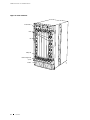
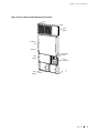
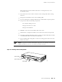
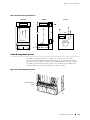
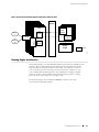
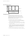
Figure 1: Front of Chassis ........................................................................ 8
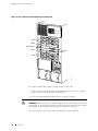
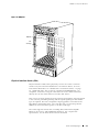
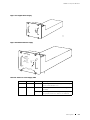
Figure 2: Rear of Chassis with Component Cover in Place ..................................... 9
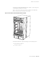
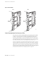
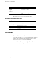
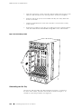
Figure 3: Rear of Chassis with Component Cover Removed .................................. 10
Figure 4: Midplane............................................................................... 13
Figure 5: Front of Chassis with Four-PIC FPC Installed in Slot FPC0.......................... 15
Figure 6: FPC1 and FPC2........................................................................ 18
Figure 7: Packet Forwarding Engine Clock Generator.......................................... 19
Figure 8: Switching and Forwarding Module ................................................... 21
Figure 9: Routing Engine........................................................................ 25
Figure 10: Miscellaneous Control Subsystem................................................... 27
Figure 11: Craft Interface........................................................................ 28
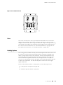
Figure 12: LCD in Idle Mode .................................................................... 30
Figure 13: LCD in Alarm Mode.................................................................. 30
Figure 14: Connector Interface Panel........................................................... 33
Figure 15: Routing Engine Interface Ports for Host Module 0 ................................ 34
Figure 16: Alarm Relay Contacts and BITS Input Ports ........................................ 35
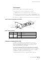
Figure 17: Original Power Supply............................................................... 37
Figure 18: Enhanced Power Supply............................................................. 37
Figure 19: Circuit Breaker Box .................................................................. 39
Figure 20: Airflow through the Chassis......................................................... 41
Figure 21: Cable Management System ......................................................... 41
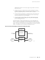
Figure 22: System Architecture ................................................................. 51
Figure 23: Packet Forwarding Engine Components and Data Flow........................... 53
Figure 24: Routing Engine Architecture ........................................................ 54
Figure 25: Control Packet Handling for Routing and Forwarding Table Updates ............. 55
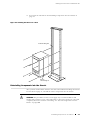
Figure 26: Typical Center-Mount Rack.......................................................... 61
Figure 27: Chassis Dimensions and Clearance Requirements................................. 62
Figure 28: Power and Grounding Cable Lug.................................................... 67
Figure 29: Typical Source Cabling to the Router ............................................... 68
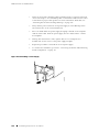
Figure 30: Power and Grounding Cable Connections.......................................... 70
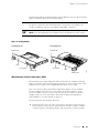
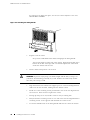
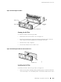
Figure 31: Unpacking the Router ............................................................... 79
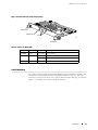
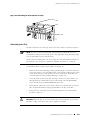
Figure 32: Removing a Power Supply .......................................................... 86
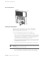
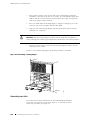
Figure 33: Removing an SFM ................................................................... 88
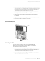
Figure 34: Removing an MCS ................................................................... 89
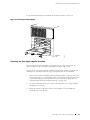
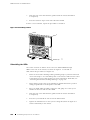
Figure 35: Removing a PCG..................................................................... 90
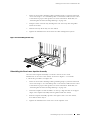
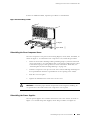
Figure 36: Removing a Routing Engine......................................................... 91
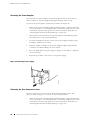
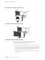
Figure 37: Removing the Rear Upper Impeller Assembly ..................................... 92
Figure 38: Removing the Rear Upper Impeller Assembly ..................................... 92
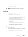
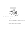
Figure 39: Removing the Rear Lower Impeller Assembly ..................................... 93
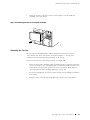
Figure 40: Removing the Fan Tray.............................................................. 94
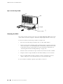
Figure 41: Removing an FPC.................................................................... 96
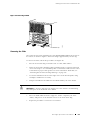
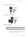
Figure 42: Removing the Front Impeller Assembly............................................ 97
Figure 43: Attaching the Lifting Handle ........................................................ 98
Figure 44: Installing the Chassis in a Rack ..................................................... 99
Figure 45: Reinstalling the Front Impeller Assembly .........................................101
Figure 46: Reinstalling an FPC .................................................................102
Figure 47: Reinstalling the Fan Tray ...........................................................103
Figure 48: Reinstalling the Rear Lower Impeller Assembly...................................104
Figure 49: Reinstalling the Rear Upper Impeller Assembly...................................105
List of F igu res xiii

M160 Internet Router Hardware Guide
Figure 50: Rei
nstalling the Rear Upper Impeller Assembly...................................105
Figure 51: Rei
nstalling a Routing Engine ......................................................106
Figure 52: Rein
stalling a PCG ..................................................................107
Figure 53: Rein
stalling an MCS ................................................................108
Figure 54: Rein
stalling an SFM.................................................................109
Figure 55: Rein
stalling a Power Supply........................................................ 110
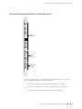
Figure 56: Rout
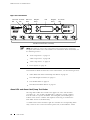
ing Engine Management Ports and Alarm Relay Contacts .................. 113
Figure 57: Rout
ing Engine Ethernet Cable Connector........................................ 114
Figure 58: Conso
le and Auxiliary Serial Port Connector...................................... 115
Figure 59: Attac
hing Cable to a PIC............................................................ 117
Figure 60: Conne
cting Power and Grounding Cables ......................................... 119
Figure 61: Removi
ng the Air Filter.............................................................129
Figure 62: Removi
ng the Filter from the Air Filter Cover.....................................129
Figure 63: Instal
ling the Air Filter..............................................................130
Figure 64: Removi
ng the CIP ..................................................................143
Figure 65: Install
ing the CIP....................................................................144
Figure 66: Routing
Engine Interface Ports and Alarm Relay Contacts .......................145
Figure 67: Etherne
t Cable Connector..........................................................146
Figure 68: Serial P
ort Connector...............................................................147
Figure 69: Removin
g the Fan Tray.............................................................149
Figure 70: Install
ing the Fan Tray ..............................................................150
Figure 71: Removing
the Front Impeller Assembly ...........................................152
Figure 72: Removing
the Screws along the Top Front Edge of the Front Impeller
Assembly...................................................................................153
Figure 73: Removing
the Craft Interface ......................................................153
Figure 74: Installi
ng the Front Impeller Assembly ............................................154
Figure 75: Removing t
he Rear Lower Impeller Assembly ....................................155
Figure 76: Installin
g the Rear Lower Impeller Assembly .....................................156
Figure 77: Removing t
he Rear Upper Impeller Assembly ....................................157
Figure 78: Removing t
he Rear Upper Impeller Assembly ....................................158
Figure 79: Installing
the Rear Upper Impeller Assembly .....................................158
Figure 80: Installing
the Rear Upper Impeller Assembly .....................................159
Figure 81: Removing a
n MCS ..................................................................161
Figure 82: Installing
an MCS ...................................................................162
Figure 83: Removing th
e PC Card .............................................................164
Figure 84: Insert the P
C Card..................................................................165
Figure85:RemovingaRo
uting Engine........................................................167
Figure 86: Installing a
Routing Engine.........................................................169
Figure 87: Removing an F
PC...................................................................172
Figure 88: Installing a
n FPC....................................................................175
Figure 89: Connecting Fi
ber-Optic Cable to a PIC ............................................176
Figure90:RemovingaPCG
....................................................................177
Figure 91: Installing a P
CG .....................................................................179
Figure92:RemovingaPIC
.....................................................................181
Figure 93: Installing a PI
C......................................................................184
Figure 94: Connecting Fib
er-Optic Cable to a PIC ............................................184
Figure 95: Connecting Fib
er-Optic Cable to a PIC ............................................187
Figure 96: Removing an SF
M ..................................................................189
Figure 97: Installing an S
FM ...................................................................190
Figure 98: Small Form Fact
or Pluggable (SFP) ................................................190
Figure 99: Removing the Ci
rcuit Breaker Box.................................................195
Figure 100: Installing th
e Circuit Breaker Box.................................................197
Figure 101: Removing a Powe
r Supply ........................................................198
Figure 102: Rear of Power Su
pply Showing Midplane Connectors...........................199
xiv List of Figures

List of Figures
Figure 103: Installing a Power Supply .........................................................200
Figure 104: Disconnecting Power Cables......................................................202
Figure 105: Connecting Power and Grounding Cables........................................204
Figure 106: Fuse Locations in the Fuse Box...................................................206
Figure 107: Fuse Locations in the Fuse Box ................................................... 211
Figure 108: Placing a Component into an Electrostatic Bag..................................227
Figure 109: Serial Number ID Label ...........................................................256
Figure 110: CIP Serial Number ID Label .......................................................257
Figure 111: Craft Interface Serial Number ID Label ...........................................258
Figure 112: DC Power Supply Serial Number ID Label........................................258
Figure 113: FPC Serial Number ID Label ......................................................259
Figure 114: MCS Serial Number ID Label......................................................260
Figure 115: PCG Serial Number ID Label .....................................................260
Figure 116: PIC Serial Number ID Label .......................................................261
Figure 117: Routing Engine 333 Serial Number ID Label.....................................261
Figure 118: Routing Engine 600 Serial Number ID Label.....................................262
Figure 119: SFMSerial Number ID Label .....................................................262
Figure 120: EIA-530 PIC........................................................................273
Figure 121: Fast Ethernet 48-port PIC .........................................................275
Figure 122: VHDCI to RJ-21 Cable .............................................................275
List of Fi gu res xv

M160 Internet Router Hardware Guide
xvi List of Figures

List of Tables
Table 1: Notice Icons ............................................................................ xx
Table 2: Text and Syntax Conventions.......................................................... xx
Table 3: Juniper Networks Technical Documentation .........................................xxi
Table 4: Field-Replaceable Units ................................................................. 4
Table 5: Chassis Physical Specifications ........................................................ 11
Table 6: States for PCG LEDs ................................................................... 19
Table 7: States for SFM LEDs.................................................................... 22
Table 8: States for MCS LEDs ................................................................... 27
Table 9: Alarm LEDs and Alarm Cutoff/Lamp Test Button .................................... 29
Table 10: States for Host Module LEDs ......................................................... 31
Table 11: States for FPC LEDs................................................................... 32
Table 12: States for Power Supply LEDs ....................................................... 37
Table 13: Electrical Specifications for Power Supply........................................... 38
Table 14: Spacing of Holes on Front Support Post and Center-Mounting Bracket............ 61
Table 15: Routing Node Environmental Specifications ........................................ 63
Table 16: Component Power Requirements ................................................... 66
Table 17: DC Power and Grounding Cable Specifications...................................... 69
Table 18: Estimated Values for Factors Causing Link Loss .................................... 73
Table 19: Cable and Wire Specifications for Routing Engine Management and Alarm
Interfaces ................................................................................... 75
Table 20: Site Preparation Checklist ............................................................ 75
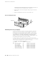
Table 21: Generic Inventory of Router Components Installed in Chassis ..................... 79
Table 22: Router Component Weights.......................................................... 83
Table 23: FPC Removal Checklist............................................................... 94
Table 24: Tools and Parts Required ............................................................140
Table 25: Fuse Specifications...................................................................206
Table 26: Chassis Alarm Messages.............................................................209
Table 27: SONET/SDH Interface Alarm Messages.............................................210
Table 28: RJ-45 Connector Pinout..............................................................269
Table 29: DB-9 Connector Pinout ..............................................................270
Table 30: RJ-48 Connector to RJ-48 Connector (Straight) Pinout .............................270
Table 31: RJ-48 Connector to RJ-48 Connector (Crossover) Pinout...........................271
Table 32: RJ-48 Connector to DB-15 Connector (Straight) Pinout ............................272
Table 33: RJ-48 Connector to DB-15 Connector (Crossover) Pinout..........................272
Table 34: DB-25 Connector to V.35 Connector Pinout ........................................273
Table 35: DB-25 Connector to DB-15 (X.21) Connector Pinout...............................274
Table 36: RJ-21 Pin Assignments...............................................................275
List of Tables xvii

M160 Internet Router Hardware Guide
xviii List of Tables

About This Guide
Objectives on page xix
Audience on page xix
Documentation Conventions on page xix
List of Technical Publications on page xxi
Documentation Feedback on page xxiii
Requesting Support on page xxiii
Objectives
This manual describes hardware installation and basic troubleshooting procedures
for the Juniper Networks M160 Internet router. It explains how to prepare your
site for router installation, unpack and install the hardware, power on the router,
perform initial software configuration, and perform routine maintenance. After
completing the installation and basic configuration p rocedures covered in this
manual, refer to the JUNOS Internet software c onfiguration guides for information
about further JUNOS software configuration.
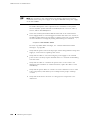
NOTE: For additional information about Juniper Networks Internet routers and the
Physical Interface Cards (PICs) they support—either corrections to or information
that might have been omitted from this guide—see the hardware release notes at
http://www.juniper.net/.
Audience
This guide is designed for network administrators who are installing and
maintaining a Juniper Networks router or preparing a site for router installation. To
use this guide, you need a broad understanding of networks in general, the Internet
in particular, networking principles, and network configuration. Any detailed
discussion of these concepts is beyond the scope of this guide.
Documentation Conventions
Table 1 defines the notice icons used in this guide.
Documentation Conventions xix

M160 Internet Router Hardware Guide
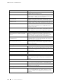
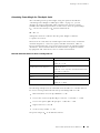
Table 1: Notice Icons
Icon Meaning Description
Informational note Indicates important features or
instructions.
Caution
Indicates a situation that might result in
loss of data or hardware damage.
Warning
Alerts you to the risk of personal injury
or death.
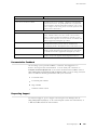
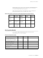
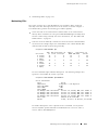
Table 2 defines the text and syntax conventions used in this guide.
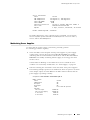
Table 2: Text and Syntax Conventions
Convention Description Examples
Bold sans serif typeface
Represents text that you type. To enter configuration mode, type the
configure command:
user@host> configure
Fixed-width typeface
Represents output that appears on the
terminal screen.
user@host> show chassis alarms
No alarms currently active
Italic typeface
Introduces important new
terms.
Identifies book names.
Identifies RFC and Internet draft
titles.
Apolicy term is a named
structure that defines match
conditions and actions.
JUNOS System Basics
Configuration Guide
RFC 1997, BGP Communities
A ttribute
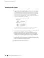
Italic sans serif typeface
Represents variables (options for which
you subst
itute a value) in commands or
configuration statements.
Configure the machine’s domain name:
[edit]
root@# set system domain-name
domain-name
Sans s erif typeface Represents names of configuration
statements, commands, files, and
directories; IP addresses; configuration
hierarchy levels; or labels on routing
platform components.
To configure a stub area,
include the stub statement at
the [edit protocols ospf area
area-id] hierarchy level.
The console port is labeled
CONSOLE.
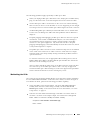
< > (angle brackets) Enclose optional keywords or variables. stub <default-metric metric >;
|(pipesymbol)
Indicates a choice between the mutually
exclusive keywords or variables on
either side of the symbol. The set of
choices is often enclosed in parentheses
for clarity.
broadcast | multicast
( string1 | string2 | string3 )
xx Documentation Conventions
La pagina si sta caricando...
La pagina si sta caricando...
La pagina si sta caricando...
La pagina si sta caricando...
La pagina si sta caricando...
La pagina si sta caricando...
La pagina si sta caricando...
La pagina si sta caricando...
La pagina si sta caricando...
La pagina si sta caricando...
La pagina si sta caricando...
La pagina si sta caricando...
La pagina si sta caricando...
La pagina si sta caricando...
La pagina si sta caricando...
La pagina si sta caricando...
La pagina si sta caricando...
La pagina si sta caricando...
La pagina si sta caricando...
La pagina si sta caricando...
La pagina si sta caricando...
La pagina si sta caricando...
La pagina si sta caricando...
La pagina si sta caricando...
La pagina si sta caricando...
La pagina si sta caricando...
La pagina si sta caricando...
La pagina si sta caricando...
La pagina si sta caricando...
La pagina si sta caricando...
La pagina si sta caricando...
La pagina si sta caricando...
La pagina si sta caricando...
La pagina si sta caricando...
La pagina si sta caricando...
La pagina si sta caricando...
La pagina si sta caricando...
La pagina si sta caricando...
La pagina si sta caricando...
La pagina si sta caricando...
La pagina si sta caricando...
La pagina si sta caricando...
La pagina si sta caricando...
La pagina si sta caricando...
La pagina si sta caricando...
La pagina si sta caricando...
La pagina si sta caricando...
La pagina si sta caricando...
La pagina si sta caricando...
La pagina si sta caricando...
La pagina si sta caricando...
La pagina si sta caricando...
La pagina si sta caricando...
La pagina si sta caricando...
La pagina si sta caricando...
La pagina si sta caricando...
La pagina si sta caricando...
La pagina si sta caricando...
La pagina si sta caricando...
La pagina si sta caricando...
La pagina si sta caricando...
La pagina si sta caricando...
La pagina si sta caricando...
La pagina si sta caricando...
La pagina si sta caricando...
La pagina si sta caricando...
La pagina si sta caricando...
La pagina si sta caricando...
La pagina si sta caricando...
La pagina si sta caricando...
La pagina si sta caricando...
La pagina si sta caricando...
La pagina si sta caricando...
La pagina si sta caricando...
La pagina si sta caricando...
La pagina si sta caricando...
La pagina si sta caricando...
La pagina si sta caricando...
La pagina si sta caricando...
La pagina si sta caricando...
La pagina si sta caricando...
La pagina si sta caricando...
La pagina si sta caricando...
La pagina si sta caricando...
La pagina si sta caricando...
La pagina si sta caricando...
La pagina si sta caricando...
La pagina si sta caricando...
La pagina si sta caricando...
La pagina si sta caricando...
La pagina si sta caricando...
La pagina si sta caricando...
La pagina si sta caricando...
La pagina si sta caricando...
La pagina si sta caricando...
La pagina si sta caricando...
La pagina si sta caricando...
La pagina si sta caricando...
La pagina si sta caricando...
La pagina si sta caricando...
La pagina si sta caricando...
La pagina si sta caricando...
La pagina si sta caricando...
La pagina si sta caricando...
La pagina si sta caricando...
La pagina si sta caricando...
La pagina si sta caricando...
La pagina si sta caricando...
La pagina si sta caricando...
La pagina si sta caricando...
La pagina si sta caricando...
La pagina si sta caricando...
La pagina si sta caricando...
La pagina si sta caricando...
La pagina si sta caricando...
La pagina si sta caricando...
La pagina si sta caricando...
La pagina si sta caricando...
La pagina si sta caricando...
La pagina si sta caricando...
La pagina si sta caricando...
La pagina si sta caricando...
La pagina si sta caricando...
La pagina si sta caricando...
La pagina si sta caricando...
La pagina si sta caricando...
La pagina si sta caricando...
La pagina si sta caricando...
La pagina si sta caricando...
La pagina si sta caricando...
La pagina si sta caricando...
La pagina si sta caricando...
La pagina si sta caricando...
La pagina si sta caricando...
La pagina si sta caricando...
La pagina si sta caricando...
La pagina si sta caricando...
La pagina si sta caricando...
La pagina si sta caricando...
La pagina si sta caricando...
La pagina si sta caricando...
La pagina si sta caricando...
La pagina si sta caricando...
La pagina si sta caricando...
La pagina si sta caricando...
La pagina si sta caricando...
La pagina si sta caricando...
La pagina si sta caricando...
La pagina si sta caricando...
La pagina si sta caricando...
La pagina si sta caricando...
La pagina si sta caricando...
La pagina si sta caricando...
La pagina si sta caricando...
La pagina si sta caricando...
La pagina si sta caricando...
La pagina si sta caricando...
La pagina si sta caricando...
La pagina si sta caricando...
La pagina si sta caricando...
La pagina si sta caricando...
La pagina si sta caricando...
La pagina si sta caricando...
La pagina si sta caricando...
La pagina si sta caricando...
La pagina si sta caricando...
La pagina si sta caricando...
La pagina si sta caricando...
La pagina si sta caricando...
La pagina si sta caricando...
La pagina si sta caricando...
La pagina si sta caricando...
La pagina si sta caricando...
La pagina si sta caricando...
La pagina si sta caricando...
La pagina si sta caricando...
La pagina si sta caricando...
La pagina si sta caricando...
La pagina si sta caricando...
La pagina si sta caricando...
La pagina si sta caricando...
La pagina si sta caricando...
La pagina si sta caricando...
La pagina si sta caricando...
La pagina si sta caricando...
La pagina si sta caricando...
La pagina si sta caricando...
La pagina si sta caricando...
La pagina si sta caricando...
La pagina si sta caricando...
La pagina si sta caricando...
La pagina si sta caricando...
La pagina si sta caricando...
La pagina si sta caricando...
La pagina si sta caricando...
La pagina si sta caricando...
La pagina si sta caricando...
La pagina si sta caricando...
La pagina si sta caricando...
La pagina si sta caricando...
La pagina si sta caricando...
La pagina si sta caricando...
La pagina si sta caricando...
La pagina si sta caricando...
La pagina si sta caricando...
La pagina si sta caricando...
La pagina si sta caricando...
La pagina si sta caricando...
La pagina si sta caricando...
La pagina si sta caricando...
La pagina si sta caricando...
La pagina si sta caricando...
La pagina si sta caricando...
La pagina si sta caricando...
La pagina si sta caricando...
La pagina si sta caricando...
La pagina si sta caricando...
La pagina si sta caricando...
La pagina si sta caricando...
La pagina si sta caricando...
La pagina si sta caricando...
La pagina si sta caricando...
La pagina si sta caricando...
La pagina si sta caricando...
La pagina si sta caricando...
La pagina si sta caricando...
La pagina si sta caricando...
La pagina si sta caricando...
La pagina si sta caricando...
La pagina si sta caricando...
La pagina si sta caricando...
La pagina si sta caricando...
La pagina si sta caricando...
La pagina si sta caricando...
La pagina si sta caricando...
La pagina si sta caricando...
La pagina si sta caricando...
La pagina si sta caricando...
La pagina si sta caricando...
La pagina si sta caricando...
La pagina si sta caricando...
La pagina si sta caricando...
La pagina si sta caricando...
La pagina si sta caricando...
La pagina si sta caricando...
La pagina si sta caricando...
La pagina si sta caricando...
La pagina si sta caricando...
La pagina si sta caricando...
La pagina si sta caricando...
La pagina si sta caricando...
La pagina si sta caricando...
La pagina si sta caricando...
La pagina si sta caricando...
La pagina si sta caricando...
La pagina si sta caricando...
La pagina si sta caricando...
La pagina si sta caricando...
La pagina si sta caricando...
La pagina si sta caricando...
La pagina si sta caricando...
La pagina si sta caricando...
La pagina si sta caricando...
La pagina si sta caricando...
La pagina si sta caricando...
La pagina si sta caricando...
La pagina si sta caricando...
La pagina si sta caricando...
La pagina si sta caricando...
La pagina si sta caricando...
La pagina si sta caricando...
La pagina si sta caricando...
La pagina si sta caricando...
La pagina si sta caricando...
La pagina si sta caricando...
La pagina si sta caricando...
La pagina si sta caricando...
La pagina si sta caricando...
La pagina si sta caricando...
La pagina si sta caricando...
La pagina si sta caricando...
La pagina si sta caricando...
La pagina si sta caricando...
La pagina si sta caricando...
La pagina si sta caricando...
La pagina si sta caricando...
La pagina si sta caricando...
La pagina si sta caricando...
La pagina si sta caricando...
La pagina si sta caricando...
La pagina si sta caricando...
La pagina si sta caricando...
-
 1
1
-
 2
2
-
 3
3
-
 4
4
-
 5
5
-
 6
6
-
 7
7
-
 8
8
-
 9
9
-
 10
10
-
 11
11
-
 12
12
-
 13
13
-
 14
14
-
 15
15
-
 16
16
-
 17
17
-
 18
18
-
 19
19
-
 20
20
-
 21
21
-
 22
22
-
 23
23
-
 24
24
-
 25
25
-
 26
26
-
 27
27
-
 28
28
-
 29
29
-
 30
30
-
 31
31
-
 32
32
-
 33
33
-
 34
34
-
 35
35
-
 36
36
-
 37
37
-
 38
38
-
 39
39
-
 40
40
-
 41
41
-
 42
42
-
 43
43
-
 44
44
-
 45
45
-
 46
46
-
 47
47
-
 48
48
-
 49
49
-
 50
50
-
 51
51
-
 52
52
-
 53
53
-
 54
54
-
 55
55
-
 56
56
-
 57
57
-
 58
58
-
 59
59
-
 60
60
-
 61
61
-
 62
62
-
 63
63
-
 64
64
-
 65
65
-
 66
66
-
 67
67
-
 68
68
-
 69
69
-
 70
70
-
 71
71
-
 72
72
-
 73
73
-
 74
74
-
 75
75
-
 76
76
-
 77
77
-
 78
78
-
 79
79
-
 80
80
-
 81
81
-
 82
82
-
 83
83
-
 84
84
-
 85
85
-
 86
86
-
 87
87
-
 88
88
-
 89
89
-
 90
90
-
 91
91
-
 92
92
-
 93
93
-
 94
94
-
 95
95
-
 96
96
-
 97
97
-
 98
98
-
 99
99
-
 100
100
-
 101
101
-
 102
102
-
 103
103
-
 104
104
-
 105
105
-
 106
106
-
 107
107
-
 108
108
-
 109
109
-
 110
110
-
 111
111
-
 112
112
-
 113
113
-
 114
114
-
 115
115
-
 116
116
-
 117
117
-
 118
118
-
 119
119
-
 120
120
-
 121
121
-
 122
122
-
 123
123
-
 124
124
-
 125
125
-
 126
126
-
 127
127
-
 128
128
-
 129
129
-
 130
130
-
 131
131
-
 132
132
-
 133
133
-
 134
134
-
 135
135
-
 136
136
-
 137
137
-
 138
138
-
 139
139
-
 140
140
-
 141
141
-
 142
142
-
 143
143
-
 144
144
-
 145
145
-
 146
146
-
 147
147
-
 148
148
-
 149
149
-
 150
150
-
 151
151
-
 152
152
-
 153
153
-
 154
154
-
 155
155
-
 156
156
-
 157
157
-
 158
158
-
 159
159
-
 160
160
-
 161
161
-
 162
162
-
 163
163
-
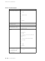 164
164
-
 165
165
-
 166
166
-
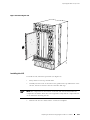 167
167
-
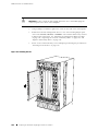 168
168
-
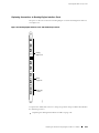 169
169
-
 170
170
-
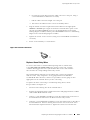 171
171
-
 172
172
-
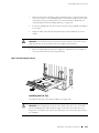 173
173
-
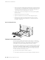 174
174
-
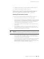 175
175
-
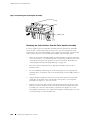 176
176
-
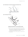 177
177
-
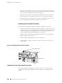 178
178
-
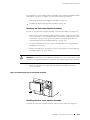 179
179
-
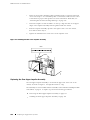 180
180
-
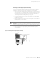 181
181
-
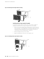 182
182
-
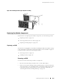 183
183
-
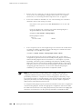 184
184
-
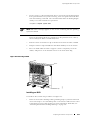 185
185
-
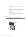 186
186
-
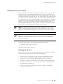 187
187
-
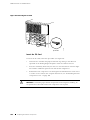 188
188
-
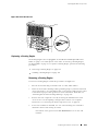 189
189
-
 190
190
-
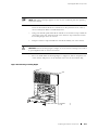 191
191
-
 192
192
-
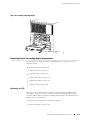 193
193
-
 194
194
-
 195
195
-
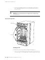 196
196
-
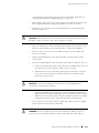 197
197
-
 198
198
-
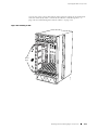 199
199
-
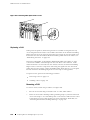 200
200
-
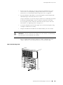 201
201
-
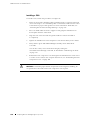 202
202
-
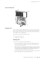 203
203
-
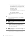 204
204
-
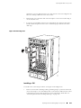 205
205
-
 206
206
-
 207
207
-
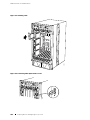 208
208
-
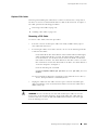 209
209
-
 210
210
-
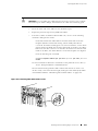 211
211
-
 212
212
-
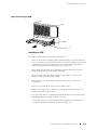 213
213
-
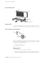 214
214
-
 215
215
-
 216
216
-
 217
217
-
 218
218
-
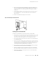 219
219
-
 220
220
-
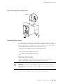 221
221
-
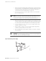 222
222
-
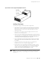 223
223
-
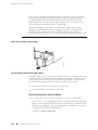 224
224
-
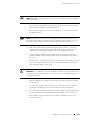 225
225
-
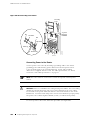 226
226
-
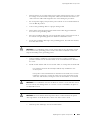 227
227
-
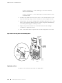 228
228
-
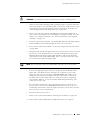 229
229
-
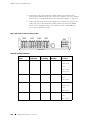 230
230
-
 231
231
-
 232
232
-
 233
233
-
 234
234
-
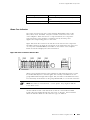 235
235
-
 236
236
-
 237
237
-
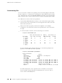 238
238
-
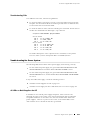 239
239
-
 240
240
-
 241
241
-
 242
242
-
 243
243
-
 244
244
-
 245
245
-
 246
246
-
 247
247
-
 248
248
-
 249
249
-
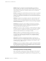 250
250
-
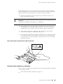 251
251
-
 252
252
-
 253
253
-
 254
254
-
 255
255
-
 256
256
-
 257
257
-
 258
258
-
 259
259
-
 260
260
-
 261
261
-
 262
262
-
 263
263
-
 264
264
-
 265
265
-
 266
266
-
 267
267
-
 268
268
-
 269
269
-
 270
270
-
 271
271
-
 272
272
-
 273
273
-
 274
274
-
 275
275
-
 276
276
-
 277
277
-
 278
278
-
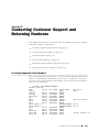 279
279
-
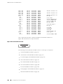 280
280
-
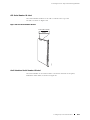 281
281
-
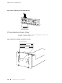 282
282
-
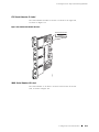 283
283
-
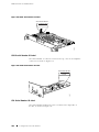 284
284
-
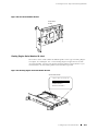 285
285
-
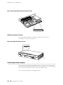 286
286
-
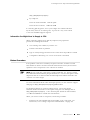 287
287
-
 288
288
-
 289
289
-
 290
290
-
 291
291
-
 292
292
-
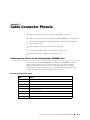 293
293
-
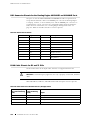 294
294
-
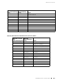 295
295
-
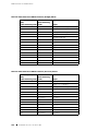 296
296
-
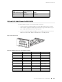 297
297
-
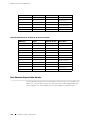 298
298
-
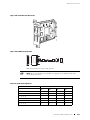 299
299
-
 300
300
-
 301
301
-
 302
302
-
 303
303
-
 304
304
-
 305
305
-
 306
306
-
 307
307
-
 308
308
-
 309
309
-
 310
310
-
 311
311
-
 312
312


Juniper Internet Router M160 Manuale utente
- Tipo
- Manuale utente
in altre lingue
Documenti correlati
-
Juniper MX104 Hardware Guide
-
Juniper J6350 Getting Started Manual
-
-
Juniper ACX500 Hardware Guide
-
-
-
-
-
-
Juniper EX2300-C Manuale utente
Altri documenti
-
KitchenAid JS48CXFXDB01 Guida d'installazione
-
Silvercrest SFM 4 A1 Operating Instructions Manual
-
 SunPower SPR-E Series Semi Flexible Solar Panel PV Modules Manuale utente
-
Intel 550F Manuale utente
-
Allied Telesis AR400 series Installation And Safety Manual
-
Intel Switch 550T Manuale utente
-
 ESD electronic I.2001.02 Manuale del proprietario
-
3M 725 Manuale utente
-
 IEI Technology PUZZLE-M801 Manuale utente
-
Intel Drums MPCMM0002 Manuale utente


