Panasonic U125PEY1E8 Istruzioni per l'uso
- Categoria
- Condizionatori d'aria a sistema split
- Tipo
- Istruzioni per l'uso

Operating Instructions
Air Conditioner
Model No.
* Shows Y1 type
(4-Way Cassette 60×60)
Indoor Units
Wall Mounted
(K1 type)
S-36PK1E5
S-45PK1E5
S-50PK1E5
S-60PK1E5
S-71PK1E5
Indoor Units
Ceiling
(T1 type)
S-36PT1E5
S-45PT1E5
S-50PT1E5
S-60PT1E5
S-71PT1E5
S-100PT1E5
S-125PT1E5
S-140PT1E5
Outdoor Units
Single Split
(Single-phase)
U-60PE1E5
U-71PE1E5
U-100PE1E5
U-125PE1E5
U-140PE1E5
U-100PEY1E5
U-125PEY1E5
(3-phase)
U-71PE1E8
U-100PE1E8
U-125PE1E8
U-140PE1E8
U-100PEY1E8
U-125PEY1E8
Indoor Units
4-Way Cassette
60×60 (Y1 type)
S-36PY1E5
S-45PY1E5
S-50PY1E5
ENGLISH
FRANÇAIS
ESPAÑOL
DEUTSCH
ITALIANO
NEDERLANDS
PORTUGUÊS
EΛΛΗΝΙΚΆ
БЪЛГАРСКИ
РУССКИЙ
УКРАЇНСЬКА
2 ~ 13
14 ~ 25
26 ~ 37
38 ~ 49
50 ~ 61
62 ~ 73
74 ~ 85
86 ~ 97
98 ~ 109
110 ~ 121
122 ~ 134
Before operating the unit, read these operating instructions thoroughly and keep them for future reference.
Avant d’utiliser l’appareil, lisez ce mode d’emploi dans son intégralité et conservez-le pour toute référence ultérieure.
Bevor Sie das Gerät in Betrieb nehmen, lesen Sie bitte diese Bedienungsanleitung aufmerksam
durch und bewahren Sie sie für die künftige Verwendung auf.
Prima di utilizzare l’unità, leggere a fondo queste istruzioni per l’uso e conservarle come riferimento futuro.
Преди да започнете експлоатация на този уред, прочетете внимателно тези инструкции и ги
запазете, за да можете да правите справки с тях и в бъдеще.
Lees deze gebruiksinstructies goed door voor u het apparaat gebruikt en bewaar ze voor toekomstig gebruik.
Antes de utilizar o aparelho, leia completamente este manual de instruções e guarde-o para futuras referências.
Перед использованием этого устройства внимательно прочитайте настоящую инструкцию по
эксплуатации и сохраните ее для дальнейших справок.
Уважно прочитайте цю інструкцію з експлуатації перед тим, як увімкнути пристрій, та
збережіть її на майбутнє.
Πριν θέσετε τη μονάδα σε λειτουργία, διαβάστε πολύ καλά αυτές τις οδηγίες χρήσης και
διατηρήστε τις για μελλοντική αναφορά.
Antes de operar la unidad, lea atentamente estas instrucciones de funcionamiento y guárdelas para futuras consultas.
CV623319882885464609176033
Panasonic Corporation
1006 Kadoma, Kadoma City, Osaka, Japan

2
CONTENTS
Page
PRODUCT INFORMATION...........................................................................................................2
SAFETY PRECAUTIONS..............................................................................................................2
INSTALLATION LOCATION...........................................................................................................3
ELECTRICAL REQUIREMENTS ..................................................................................................3
SAFETY INSTRUCTIONS.............................................................................................................4
INFORMATION..............................................................................................................................6
OPERATION..................................................................................................................................7
ADJUSTING AIRFLOW DIRECTION............................................................................................8
ADJUSTING AIRFLOW DIRECTION FOR MULTIPLE INDOOR UNITS USING SINGLE
REMOTE CONTROLLER (WIRED) ............................................................................................10
SPECIAL REMARKS ..................................................................................................................11
CARE AND CLEANING ..............................................................................................................11
TROUBLESHOOTING ................................................................................................................12
CHECK BEFORE REQUIRING SERVICES................................................................................13
TIPS FOR ENERGY SAVING .....................................................................................................13
SPECIFICATIONS.....................................................................................................................135
PRODUCT INFORMATION
If you have problems or questions concerning your Air Conditioner, you will need the following
information. Model and serial numbers are on the nameplate on the bottom of the cabinet.
Model No. _________________________________ Serial No. _______________________
Date of purchase ______________________________________________________________
Dealer’s address ______________________________________________________________
Phone number________________________________________________________________
SAFETY PRECAUTIONS
The following symbols used in this manual, alert you to potentially dangerous conditions
to users, service personnel or the appliance:
This symbol refers to a hazard or unsafe practice
which can result in severe personal injury or
death.
This symbol refers to a hazard or unsafe practice
which can result in personal injury or product or
property damage.
01_85464609176033_EN.fm Page 2 Monday, November 12, 2012 9:58 AM

3
INSTALLATION LOCATION
• We recommend that this air conditioner be installed properly by qualified installation
technicians in accordance with the Installation Instructions provided with the unit.
• Before installation, check that the voltage of the electric supply in your home or office is the
same as the voltage shown on the nameplate.
ELECTRICAL REQUIREMENTS
1. All wiring must conform to the local electrical codes. Consult your dealer or a qualified
electrician for details.
2. Each unit must be properly grounded with a ground (or earth) wire or through the supply
wiring.
3. Wiring must be done by a qualified electrician.
• Do not install this air conditioner where there are fumes or flammable gases, or in an
extremely humid space such as a greenhouse.
• Do not install the air conditioner where excessively high heat-generating objects
are placed.
Avoid: To protect the air conditioner from heavy corrosion, avoid installing the outdoor unit where
salty sea water can splash directly onto it or in sulphurous air near a spa.
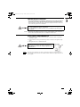
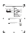
To warm up the system, the power mains must be turned on
at least five (5) hours before operation. Leave the power
mains ON unless you will not be using this appliance for an
extended period.
Pull off the power plug from a receptacle, or switch off the breaker, or switch off the power
disconnecting mean to isolate the air conditioner from the main power supply when not in use
for a long time.
Power mains
ON
NOTE
01_85464609176033_EN.fm Page 3 Monday, November 12, 2012 9:58 AM

4
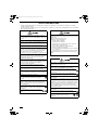
SAFETY INSTRUCTIONS
• Read these Operating Instructions carefully before using this air conditioner. If you still have any difficulties or problems,
consult your dealer for help.
• This air conditioner is designed to give you comfortable room conditions. Use this only for its intended purpose as described in
these Operating Instructions.
Confirm to authorized dealer or specialist on usage of
specified refrigerant type. Using of refrigerant other than
the specified type may cause product damage, burst and
injury etc.
Never touch the unit with wet hands.
Never use or store gasoline or other flammable vapor or
liquid near the air conditioner — it is very dangerous.
Do not use this appliance in a potentially explosive
atmosphere.
This air conditioner has no ventilator for intaking fresh air
from outdoors. You must open doors or windows frequently
when you use gas or oil heating appliances in the same
room, which consume a lot of oxygen from the air.
Otherwise there is a risk of suffocation in an extreme case.
Provide a power outlet to be used exclusively for each unit,
and a power supply disconnect, circuit breaker and earth
leakage breaker for overcurrent protection should be
provided in the exclusive line.
Provide a power outlet exclusively for each unit, and full
disconnection means having a contact separation in all
poles must be incorporated in the fixed wiring in
accordance with the wiring rules.
To prevent possible hazards from insulation failure,
the unit must be grounded.
Do not clean inside the indoor and outdoor units by users.
Engage authorized dealer or specialist for cleaning.
In case of malfunction of this appliance, do not repair by
yourself. Contact to the sales dealer or service dealer for a
repair.
Refrigerant gas leakage may cause fire.
For safety, be sure to turn the air conditioner off and
also to disconnect the power before cleaning or
servicing.
Pull off the power plug from a receptacle, or switch off the
breaker, or switch off the power disconnecting mean to
isolate the air conditioner from the main power supply in
case of emergency.
Do not insert your fingers or other objects into the air
conditioner indoor or outdoor unit, rotating parts may
cause injury.
Do not use modified cord, joint cord, extension
cord or unspecified cord to prevent overheating
and fire.
Stop using the product when any abnormality/failure occurs
and disconnect the power plug or turn off the power switch
and breaker.
(Risk of smoke/fire/electric shock)
Examples of abnormality/failure
• The ELCB trips frequently.
• Burning smell is observed.
• Abnormal noise or vibration of the unit is observed.
• Water leaks from the indoor unit.
• Power cord or plug becomes abnormally hot.
• Fan speed cannot be controlled.
• The unit stops running immediately even if it is switched
on for operation.
• The fan does not stop even if the operation is stopped.
Contact immediately your local dealer for maintenance/
repair.
This appliance is intended to be used by expert or trained
users in shops, in light industry and on farms, or for
commercial use by lay persons.
Do not turn the air conditioner on and off from the power
mains switch. Use the ON/OFF operation button.
Do not stick anything into the air outlet of the outdoor
unit. This is dangerous because the fan is rotating at
high speed.
Do not touch the air inlet or the sharp aluminum fins
of the outdoor unit. You may get injured.
Keep the fire alarm and the air outlet at least 1.5m away
from the unit.
This appliance is not intended for use by persons(including
children) with reduced physical, sensory or mental
capabilities, or lack of experience and knowledge, unless
they have been given supervision or instruction concerning
use of the appliance by a person responsible for their
safety. Children should be supervised to ensure that do not
play with the appliance.
Do not cool or heat the room too much if babies or invalids
are present.
Do not sit or step on the unit. You may fall down
accidentally.
Do not stick any object into the FAN CASE.
You may be injured and the unit may be
damaged.
01_85464609176033_EN.fm Page 4 Monday, November 12, 2012 9:58 AM

5
• The compressor may occasionally stop during thunderstorms.
This is not a mechanical failure. The unit automatically recovers after a few minutes.
• The English text is the original instructions. Other languages are translation of the
original instructions.
Stop using the product when any abnormality/failure occurs and
disconnect the power plug.
(Risk of smoke/fire/electric shock)
Examples of
abnormality/
failure
- The product sometimes does not start when turned on.
- The power is sometimes disconnected when the cord is moved.
- Burnt odor or abnormal noise is detected during operation.
- The body is deformed or abnormally hot.
Contact immediately your local dealer for maintenance/repair.
NOTICE
01_85464609176033_EN.fm Page 5 Monday, November 12, 2012 9:58 AM

6
INFORMATION
Operation Condition
Use this air conditioner under the following temperature range.
Indoor temperature range:
Cooling mode 14°C ~ 25°C (*WBT) / 18°C ~ 32°C (*DBT)
Heating mode 16°C ~ 30°C (*DBT)
Outdoor temperature range:
Cooling mode -15°C ~ 46°C (*DBT)
*1 -10°C ~ 43°C (*DBT)
Heating mode -20°C ~ 18°C (*WBT) / -20°C ~ 24°C (*DBT)
*1 -15°C ~ 18°C (*WBT) / -15°C ~ 24°C (*DBT)
*DBT: Dry bulb temperature
*WBT: Wet bulb temperature
*1 When connecting U-100PEY1E5, U-100PEY1E8, U-125PEY1E5, U-125PEY1E8
Information for Users on Collection and Disposal of Old Equipment and Used Batteries
These symbols on the products, packaging, and/or accompanying documents mean that used electrical and
electronic products and batteries should not be mixed with general household waste.
For proper treatment, recovery and recycling of old products and used batteries, please take them to
applicable collection points, in accordance with your national legislation and the Directives 2002/96/EC and
2006/66/EC.
By disposing of these products and batteries correctly, you will help to save valuable resources and prevent
any potential negative effects on human health and the environment which could otherwise arise from
inappropriate waste handling.
For more information about collection and recycling of old products and batteries, please contact your local
municipality, your waste disposal service or the point of sale where you purchased the items.
Penalties may be applicable for incorrect disposal of this waste, in accordance with national legislation.
For business users in the European Union
If you wish to discard electrical and electronic equipment, please contact your dealer or supplier for further
information.
[Information on Disposal in other Countries outside the European Union]
These symbols are only valid in the European Union. If you wish to discard these items, please contact your
local authorities or dealer and ask for the correct method of disposal.
Note for the battery symbol (bottom two symbol examples):
This symbol might be used in combination with a chemical symbol. In this case it complies with the requirement
set by the Directive for the chemical involved.
Pb
01_85464609176033_EN.fm Page 6 Monday, November 12, 2012 9:58 AM

7
OPERATION
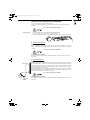
Names of Parts
INDOOR UNIT
Wireless Remote Controller (Optional parts)
Timer Remote Controller (Optional parts)
Refer to the Operating Instructions attached to the
optional Wireless Remote Controller.
Refer to the Operating Instructions attached to the
optional Timer Remote Controller.
Y1 type (4-Way Cassette 60×60)
Water drain
Ceiling panel
(optional)
Air outlet
(4 locations)
Air intake grille
(air intake)
Water drain
(You can
connect the
drain pipe
either the right
or left side.)
Air intake
grille
(air intake)
Air outlet
T1 type (Ceiling)
Air intake
Air outlet
K1 type (Wall Mounted)
NOTE
(Wireless type: available
for all indoor units)
NOTE
(Wired type: available
for all indoor units)
01_85464609176033_EN.fm Page 7 Monday, November 12, 2012 9:58 AM

8
ADJUSTING AIRFLOW DIRECTION
The functions differ depending on the indoor unit used. The airflow direction cannot be set
using the remote controller for any unit which is not listed below.
Y1 type, T1 type, K1 type:
• Never use your hands to move the flap (vertical airflow flap) that is controlled using the
remote controller.
• When the air conditioner is turned off, the flap (vertical airflow flap) automatically moves to
the downward position.
• The flap (vertical airflow flap) moves to the upward position when performing the standby
operation for heating. The swing operation is made after the standby operation for heating is
released, but swing is indicated on the remote controller even during the standby operation
for heating.
Setting the airflow
direction
The airflow direction changes each time the FLAP button is pressed during operation.
To activate the swing
operation
Press the FLAP button to set the flap (vertical airflow flap) to the downward position, and then
press the FLAP button again. This displays , and the airflow automatically swings up and
down.
To stop the swing
operation
Press the FLAP button again during the flap swing operation to stop the flap at the desired
position. Then, the airflow can be set from the top position by pressing the FLAP button again.
Indicator when swing operation is stopped
During cooling or drying operation, the flap will not stop at the downward position. Even if the
flap is stopped at the downward position during the swing operation, it will not stop until it
moves to the third position from the top.
Heating Cooling and drying Fan operation All operations
Set the flap (vertical airflow flap) to the downward
position. If the flap is set to the upward position,
the warm air may not reach the floor.
The flap (vertical airflow flap) can
be set to one of three positions.
Initial setting
Initial setting
Initial setting
Continuous
operation
Fan and heating Cooling and drying
01_85464609176033_EN.fm Page 8 Monday, November 12, 2012 9:58 AM

9
ADJUSTING AIRFLOW DIRECTION (CONTINUED)
Y1 type air conditioner is equipped with auto flaps.
You can set the airflow direction to a specific angle or to the sweep mode using the remote
controller.
Do not move the flap with your hands.
4-way (Y1 type) • The air outlet flap can be easily removed and washed with water.
• Be sure to always stop operation before removing the flap.
• After washing with water, allow it to dry, and then remount it with the arrow facing outward.
Ceiling mounted type (T1)
Vertical directions (automatic)
This air conditioner is equipped with an auto flap. You can set the airflow direction to a specific
angle or to the sweep mode using the remote controller. (Refer to the description of the remote
controller.)
Do not move the flap with your hands.
Horizontal directions (manual)
The horizontal airflow direction can be adjusted manually by moving the vertical vanes to the
left or right.
Wall mounted type (K1)
Vertical directions (automatic)
Confirm that the remote controller has been turned on. Press the FLAP button to start the flap
moving up and down. If you want to stop the flap movement and to direct the air in the desired
direction, press the FLAP button again. In the cool mode, do not direct the flap down and move
out of the cooling zone “A”, otherwise, condensation may drip on to the floor. Zone ‘‘A’’ is the
recommended flap position for cooling.
When operating continuously in the fixed airflow direction setting for about an hour, the airflow
direction is automatically controlled and the flap position is changed. The airflow direction may
be different from the display on the remote controller.
Do not move the flap with your hands.
Horizontal directions (manual)
The horizontal airflow direction can be adjusted manually by moving the vertical vanes to the
left or right.
Indoor unit
Zone ‘‘B’’ for
heating
Zone
‘‘A’’ for
cooling
01_85464609176033_EN.fm Page 9 Monday, November 12, 2012 9:58 AM

10
ADJUSTING AIRFLOW DIRECTION FOR MULTIPLE
INDOOR UNITS USING SINGLE REMOTE
CONTROLLER (WIRED)
• If multiple indoor units are connected to a remote controller, the airflow direction can be set
for each indoor unit by selecting the indoor units (see the operation below).
Auto Flap ( ) button
• To set the airflow for individual units, press the UNIT button. Display shows the indoor unit
number under group control. Set the airflow direction for the indoor unit that is shown on the
display.
• Each time UNIT is pressed, the indicator changes in the order shown below.
• When nothing is displayed, you can make the setting for all indoor units in one operation.
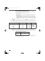
• The unit number is displayed as Outdoor Unit Number–Indoor Unit Number. It varies
depending on the number of units under group control.
One outdoor unit and eight indoor units Two outdoor units and four indoor units
No display
Unit No.
1–1
Unit No.
1–2
Unit No.
1–3
Unit No.
1–8
No
display
Unit
No.
1–1
Unit
No.
1–2
Unit
No.
1–3
Unit
No.
2–4
Unit
No.
1–4
Unit
No.
2–1
01_85464609176033_EN.fm Page 10 Monday, November 12, 2012 9:58 AM

11
SPECIAL REMARKS
CARE AND CLEANING
How it works • Once the room temperature reaches the level that was set, the unit repeats the cycle of
turning on and off automatically.
• In order to prevent the humidity in the room from rising again, the indoor fan also turns off
when the unit stops operating.
• The fan speed is set to ‘‘LO.’’ automatically, and cannot be adjusted.
• ‘‘DRY’’ operation is not possible if the outdoor temperature is 15 °C or less.
Heating performance • Because this appliance heats a room by utilizing the heat of the outside air (heat pump
system), the heating efficiency will fall off when the outdoor temperature is very low. If
sufficient heat cannot be obtained with this heat pump, use another heating appliance in
conjunction with this unit.
Defrosting • When the outdoor temperature is low, frost or ice may form on the outdoor heat exchanger
coil, reducing the heating performance. When this happens, a microcomputer-controlled
defrosting system operates. At the same time, the fan on the indoor unit stops (or runs at
very low speed in some cases) and the ‘‘STANDBY’’ indicator appears on the display until
defrosting is completed. Heating operation then restarts after several minutes. (This interval
will vary slightly depending upon the outdoor temperature and the way in which frost forms.)
(standby) on the
display
• For several minutes after the start of heating operation, the indoor fan will not start running
(or it will run at very low speed in some cases) until the indoor heat exchanger coil has
warmed up sufficiently. This is because a cold draft prevention system is operating. During
this period, the ‘‘ ’’ (standby) indicator remains displayed.
• ‘‘ ’’ (standby) remains displayed during defrosting or when the compressor has been
turned off (or when the unit is running at very low speed) by the thermostat when the
system is in the heating mode.
• Upon completion of defrosting and when the compressor is turned on again, ‘‘ ’’
(standby) will turn off automatically as heating operation resumes.
Should the power fail while the unit is running
If the power supply for this unit is temporarily cut off, the unit will automatically resume
operation (once the power is restored) using the same settings before the power was cut off.
1. For safety, be sure to turn the air conditioner off and also to disconnect the power
before cleaning.
2. Do not pour water on the indoor unit to clean it. This will damage the internal
components and cause an electric shock hazard.
Air intake and outlet side
(Indoor unit)
Clean the air intake and outlet side of the indoor unit with a vacuum cleaner brush, or wipe
them with a clean, soft cloth.
If these parts are stained, use a clean cloth moistened with water. When cleaning the air outlet
side, be careful not to force the vanes out of place.
1. Never use solvents or harsh chemicals when cleaning the indoor unit. Do not wipe
plastic parts using very hot water.
2. Some metal edges and the fins are sharp and may cause injury if handled
improperly; be especially careful when you clean these parts.
3. The internal coil and other components of the outdoor unit must be cleaned
periodically. Consult your dealer or service center.
‘‘DRY’’ Operation
Heating Operation
NOTE
01_85464609176033_EN.fm Page 11 Monday, November 12, 2012 9:58 AM

12
TROUBLESHOOTING
If your air conditioner does not work properly, first check the following points before requesting service. If it still does not work
properly, contact your dealer or a service center.
INDOOR UNIT
OUTDOOR UNIT
Symptom Cause
Noise Sound like streaming water during
operation or after operation
• Sound of refrigerant liquid flowing inside unit
• Sound of drainage water through drain pipe
Cracking noise during operation or
when operation stops.
Cracking sound due to temperature changes of parts
Odor Discharged air is smelled during
operation.
Indoor odor components, cigarette odor and cosmetic odor accumurated
in the air conditioner and its air is discharged.
Unit inside is dusty. Consult your dealer.
Dewdrop Dewdrop gets accumurated near air
discharge during operation
Indoor moisture is cooled by cool wind and accumulated by dewdrop.
Fog Fog occurs during operation in cooling
mode.
(Places where large amounts of oil
mist exist at restaurants.)
• Cleaning is necessary because unit inside (heat exchanger) is dirty.
Consult your dealer as technical engineering is required.
• During defrost operation
Fan is rotating for a while even though operation
stops.
• Fan rotating makes operation smoothly.
• Fan may sometimes rotates because of drying heat exchanger due to
settings.
Wind-direction changes while operating.
Wind-direction setting cannot be made.
Wind-direction cannot be changed.
• When air discharge temperature is low or during defrost operation,
horizontal wind flow is made automatically.
• Flap position is occasionally set up individually.
When wind-direction is changed, flap operates
several times and stops at designated position.
When wind-direction is changed, flap operates after searching for
standard position.
Dust Dust accumulation inside indoor unit is discharged.
At the initial high-speed operation, the fan may
sometimes rotate faster (for 3 to 30 minutes) than
the setting speed.
This is for operation check in order to confirm whether the fan motor
rotation is within use range.
Symptom Cause
No
operation
When power is turned ON instantly. Operation is not activated for the first approx. 3 minutes because
compressor protection circuit is activated.
When operation is stopped and
resumed immediately.
Noise Noise often occurs in heating mode. During defrost operation
Steam Steam often occurs in heating mode.
When stopped by remote controller, outdoor unit fan
is sometimes operating for a while even though
outdoor compressor is stopped.
Fan rotating makes operation smoothly.
01_85464609176033_EN.fm Page 12 Monday, November 12, 2012 9:58 AM

13
CHECK BEFORE REQUIRING SERVICES
If your air conditioner still does not work properly although you checked the points as described above, first stop the operation and
turn off the power switch. Then contact your dealer and report the serial number and symptom. Never repair your air conditioner
by yourself since it is very dangerous for you to do so. You also report if the inspection mark and the letters E, F, H, L, P in
combination with the numbers appear on the LCD of the remote control unit.
TIPS FOR ENERGY SAVING
Avoid
• Do not block the air intake and outlet of the unit. If either is obstructed, the unit will not work well, and may be
damaged.
• Do not let direct sunlight into the room. Use sunshades, blinds or curtains. If the walls and ceiling of the room are warmed by
the sun, it will take longer to cool the room.
Do
• Always try to keep the air filter clean. (Refer to “CARE AND CLEANING”.) A clogged filter will impair the performance of the
unit.
• To prevent conditioned air from escaping, keep windows, doors and any other openings closed.
Should the power fail while the unit is running
If the power supply for this unit is temporarily cut off, the unit will automatically resume operation once power is restored using the
same settings before the power was interrupted.
Symptom Cause Remedy
Air conditioner does not run at
all although power is turned
on.
Power failure or after power failure Press ON/OFF operation button on remote control
unit again.
Operation button is turned off. • Switch on power if breaker is turned off.
• If breaker has been tripped, consult your dealer
without turning it on.
Fuse blow out. If blown out, consult your dealer.
Poor cooling or heating
performance
Air intake or air discharge port of indoor
and outdoor units is clogged with dust or
obstacles.
Remove dust or obstruction.
Wind speed switch is set to “Low”. Change to “High” or “Strong”.
Improper temperature settings Refer to “TIPS FOR ENERGY SAVING”.
Room is exposed to direct sunlight in
cooling mode.
Doors and /or windows are open.
Air filter is clogged. Refer to “CARE AND CLEANING”.
Too much heat sources in room in
cooling mode.
Use minimum heat sources and in a short time.
Too many people in room in cooling
mode.
Reduce temperature settings or change to “High” or
“Strong”.
NOTE
01_85464609176033_EN.fm Page 13 Monday, November 12, 2012 9:58 AM

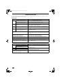
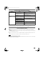
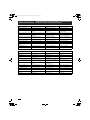
135
4-Way Cassette 60x60 (Y1 type)
Wall Mounted (K1 type)
Model Name
S-36PY1E5 S-45PY1E5 S-50PY1E5
Power Source
220 - 230 - 240 V, single-phase, 50/60 Hz
Cooling capacity
kW 3.6 4.5 5.0
BTU / h 12,300 15,400 17,100
Heating capacity
kW 4.2 5.2 5.6
BTU / h 14,300 17,700 19,100
Sound
Pressure
level
High dB(A) 32 36 41
Medium dB(A) 29 32 37
Low dB(A) 26 28 33
Sound
Power level
High dB(A) 49 53 58
Medium dB(A) 46 48 54
Low dB(A) 42 45 50
Unit Dimensions (H×W×D)
mm
313×625×625 313×625×625 313×625×625
Net weight kg 18.4 18.4 18.4
Model Name
S-36PK1E5 S-45PK1E5 S-50PK1E5 S-60PK1E5 S-71PK1E5
Power Source 220 - 230 - 240 V, single-phase, 50/60 Hz
Cooling capacity
kW 3.6 4.5 5.0 6.0 7.1
BTU / h 12,300 15,400 17,100 20,500 24,200
Heating capacity
kW 4.2 5.2 5.6 7.0 8.0
BTU / h 14,300 17,700 19,100 23,900 27,300
Sound
Pressure
level
High dB(A) 35 38 40 47 47
Medium dB(A) 31 34 36 44 44
Low dB(A) 27 30 32 40 40
Sound
Power level
High dB(A) 52 55 57 64 64
MediumdB(A)4649515959
Low dB(A) 41 44 46 54 54
Unit Dimensions (H×W×D)
mm
300×1,065×230 300×1,065×230 300×1,065×230 300×1,065×230 300×1,065×230
Net weight kg 13 13 13 14.5 14.5
SPECIFICATIONS
12_85464609176033_Spec.fm Page 135 Monday, November 12, 2012 10:06 AM

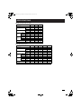
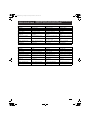
136
Ceiling (T1 type)
Model Name
S-36PT1E5 S-45PT1E5 S-50PT1E5 S-60PT1E5 S-71PT1E5
S-100PT1E5 S-125PT1E5 S-140PT1E5
Power Source 220 - 230 - 240 V, single-phase, 50/60 Hz
Cooling capacity
kW 3.6 4.5 5.0 6.0 7.1 10.0 12.5 14.0
BTU / h 12,300 15,400 17,100 20,500 24,200 34,100 42,700 47,800
Heating capacity
kW 4.2 5.2 5.6 7.0 8.0 11.2 14.0 16.0
BTU / h 14,300 17,700 19,100 23,900 27,300 38,200 47,800 54,600
Sound
Pressure
level
High dB(A) 35 38 38 39 39 42 45 46
Medium dB(A) 32 33 33 36 36 38 40 41
Low dB(A) 30 30 30 33 33 35 37 38
Sound
Power level
High dB(A) 53 57 57 58 58 61 63 64
Medium dB(A) 50 51 51 53 53 56 58 59
Low dB(A) 46 46 46 50 50 53 55 56
Unit Dimensions (H×W×D)
mm
210×910×680 210×910×680 210×910×680
210×1,180×680 210×1,180×680 210×1,595×680 210×1,595×680 210×1,595×680
Net weight kg 21 21 21 25 25 33 33 33
SPECIFICATIONS
12_85464609176033_Spec.fm Page 136 Monday, November 12, 2012 10:06 AM

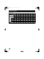
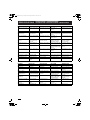
137
Single Split Outdoor Unit
Model Name
U-60PE1E5 U-71PE1E5 U-100PE1E5 U-125PE1E5 U-140PE1E5
Power Source
220 - 230 - 240 V, single-phase, 50 Hz
Cooling capacity
kW 6.0 7.1 10.0 12.5 14.0
BTU / h 20,500 24,200 34,100 42,700 47,800
Heating capacity
kW 7.0 8.0 11.2 14.0 16.0
BTU / h 23,900 27,300 38,200 47,800 54,600
Sound Pressure level (C/H)
dB(A) 48/50 48/50 52/52 53/53 54/55
Sound Power level (C/H) dB(A) 65/67 65/67 69/69 70/70 71/71
Unit Dimensions (H×W×D)
mm
996×940×340 996×940×340
1,416×940×340 1,416×940×340 1,416×940×340
Net weight kg 68 69 98 98 98
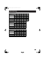
Model Name
U-71PE1E8 U-100PE1E8 U-125PE1E8 U-140PE1E8
Power Source
380 - 400 - 415 V, 3-phase, 50 Hz
Cooling capacity
kW 7.1 10.0 12.5 14.0
BTU / h 24,200 34,100 42,700 47,800
Heating capacity
kW 8.0 11.2 14.0 16.0
BTU / h 27,300 38,200 47,800 54,600
Sound Pressure level (C/H)
dB(A) 48/50 52/52 53/53 54/55
Sound Power level (C/H) dB(A) 65/67 69/69 70/70 71/71
Unit Dimensions (H×W×D)
mm
996×940×340
1,416×940×340 1,416×940×340 1,416×940×340
Net weight kg 69 98 98 98
Model Name
U-100PEY1E5 U-125PEY1E5 U-100PEY1E8 U-125PEY1E8
Power Source
220 - 230 - 240 V, single-phase, 50 Hz
380 - 400 - 415 V, 3-phase, 50 Hz
Cooling capacity
kW 10.0 12.5 10.0 12.5
BTU / h 34,100 42,700 34,100 42,700
Heating capacity
kW 10.0 12.5 10.0 12.5
BTU / h 34,100 42,700 34,100 42,700
Sound Pressure level (C/H)
dB(A) 54/54 56/56 54/54 56/56
Sound Power level (C/H) dB(A) 70/70 73/73 70/70 73/73
Unit Dimensions (H×W×D)
mm
996×940×340
996×940×340 996×940×340 996×940×340
Net weight kg 73 85 73 85
SPECIFICATIONS
12_85464609176033_Spec.fm Page 137 Monday, November 12, 2012 10:06 AM

138
English Français Español Deutsch
4-Way Cassette (U1 type) Cassette 4 voies (Type U1) Cassette de 4 vías (tipo U1) 4-Weg Kassette (Typ U1)
Ceiling (T1 type) Plafond (Type T1) Techo (tipo T1) Deckenmontage (Typ T1)
High Static Pressure Ducted (E1
type)
Conduit Haute Pression Statique
(Type E1)
Conductos de presión estática
alta (tipo E1)
Kanalgerät mit hoher statischer
Pressung (Typ E1)
4-Way Cassette 60x60 (Y1 type) Cassette 4 voies 60x60 (Type Y1) Cassette de 4 vías 60x60 (tipo Y1) 4-Weg Kassette 60 x 60 (Typ Y1)
Slim Low Static Ducted (M1 type) Conduit Mince Faible Statique
(Type M1)
Conductos finos de presión
estática baja (tipo M1)
Flaches Kanalgerät mit niedriger
statischer Pressung (M1)
Low Silhouette Ducted (F1 type) Conduit Silhouette Basse
(Type F1)
Conductos de silueta baja
(tipo F1)
Kanalgerät, flache Bauform (Typ
F1)
2-Way Cassette (L1 type) Cassette 2 voies (Type L1) Cassette de 2 vías (tipo L1) 2-Weg Kassette (Typ L1)
1-Way Cassette (D1 type) Cassette 1 voie (Type D1) Cassette de 1 vía (tipo D1) 1-Weg Kassette (Typ D1)
Floor Standing (P1 type) Vertical au sol (Type P1) De pie (tipo P1) Bodenaufstellung (Typ P1)
Concealed Floor Standing
(R1 type)
Vertical au sol caché (Type R1) De pie y oculto (tipo R1) Bodenaufstellung/Einbau (Typ R1)
Wall Mounted (K1 type) Monté au mur (Type K1) Montado en pared (tipo K1) Wandmontage (Typ K1)
Single Split Bibloc simple Partición única Einzel-Split
English Italiano Nederlands Português
4-Way Cassette (U1 type) A cassetta a 4 vie (tipo U1) 4-weg cassette (type U1) Cassete de 4 vias (Tipo U1)
Ceiling (T1 type) A soffitto (tipo T1) Plafond (type T1) Tecto (Tipo T1)
High Static Pressure Ducted
(E1 type)
A condotto ad alta pressione
statica (tipo E1)
Kanaalmodel met hoge statische
druk (type E1)
Pressão estática elevada no tubo
(Tipo E1)
4-Way Cassette 60x60 (Y1 type) A cassetta a 4 vie 60x60 (tipo Y1) 4-weg cassette 60x60 (type Y1) Cassete de 4 vias 60x60 (Tipo Y1)
Slim Low Static Ducted (M1 type) Sottile a condotto a bassa
pressione statica (tipo M1)
Slank laag statisch kanaalmodel
(type M1)
Estática baixa fina no tubo
(Tipo M1)
Low Silhouette Ducted (F1 type) A profilo basso a condotto
(tipo F1)
Kanaalmodel met onopvallend
silhouet (type F1)
Baixo perfil no tubo (Tipo F1)
2-Way Cassette (L1 type) A cassetta a 2 vie (tipo L1) 2-weg cassette (type L1) Cassete de 2 vias (Tipo L1)
1-Way Cassette (D1 type) A cassetta a 1 via (tipo D1) 1-weg cassette (type D1) Cassete de 1 via (Tipo D1)
Floor Standing (P1 type) A pavimento (tipo P1) Vloermodel (type P1) Montagem no chão (Tipo P1)
Concealed Floor Standing
(R1 type)
A pavimento nascosto (tipo R1) Verborgen vloermodel (type R1) Montagem no chão oculta
(Tipo R1)
Wall Mounted (K1 type) Con montaggio a parete (tipo K1) Wandmodel (K1) Montagem na parede (Tipo K1)
Single Split Split singolo Enkele splitsing Duas unidades
SPECIFICATIONS
CARACTÉRISTIQUES / ESPECIFICACIONES / TECHNISCHE DATEN /
SPECIFICHE / SPECIFICATIE / ESPECIFICAÇÕES
12_85464609176033_Spec.fm Page 138 Monday, November 12, 2012 10:06 AM

139
English Français Español Deutsch
Model Name Nom du modèle Nombre del modelo Modellbezeichnung
Power Source Source d'alimentation Fuente de alimentación Spannungsquelle
Cooling Capacity Capacité de refroidissement Capacidad de refrigeración Kühlleistung
Heating Capacity Capacité de chauffage Capacidad de calefacción Heizleistung
Sound Pressure Level (High/
Medium/Low)
Niveau de pression sonore (Haut/
Moyen/Bas)
Nivel de presión acústica (alto/
medio/bajo)
Schalldruckpegel (hoch/mittel/
niedrig)
Sound Power Level (High/
Medium/Low)
Niveau de puissance sonore
(Haut/Moyen/Bas)
Nivel de potencia acústica (alto/
medio/bajo)
Schallleistungspegel (hoch/mittel/
niedrig)
Unit Dimensions (HxWxD; mm) Dimensions d'unité (HxLxP ; mm) Dimensiones de la unidad (Alto x
Largo x Ancho; mm)
Geräteabmessungen (H x B x T
[mm])
(HxWxD: ceiling dimension) (HxLxP : dimensions plafond) (Alto x Largo x Ancho: dimensión
del techo)
(H x B x T: Deckenmaß)
Net Weight (kg) Poids net (kg) Peso neto (kg) Nettogewicht (kg)
English Italiano Nederlands Português
Model Name Modello Modelnaam Nome do modelo
Power Source Fonte di alimentazione Voeding Fonte de alimentação
Cooling Capacity Capacità di raffreddamento Koelingscapaciteit Capacidade de arrefecimento
Heating Capacity Capacità di riscaldamento Verwarmingscapaciteit Capacidade de aquecimento
Sound Pressure Level (High/
Medium/Low)
Livello di pressione acustica (alto/
medio/basso)
Geluidsdrukniveau (hoog/
normaal/laag)
Nível da pressão do som (Alto/
Médio/Baixo)
Sound Power Level (High/
Medium/Low)
Livello di potenza acustica (alto/
medio/basso)
Geluidsvermogenniveau (hoog/
normaal/laag)
Nível da potência de som (Alto/
Médio/Baixo)
Unit Dimensions (HxWxD; mm) Dimensioni unità (AxLxP; mm) Afmetingen van de unit (H x B x D;
mm)
Dimensões da unidade (AxLxP;
mm)
(HxWxD: ceiling dimension) (AxLxP: dimensione soffitto) (H x B x D: plafondafmeting) (AxLxP: dimensão do tecto)
Net Weight (kg) Peso netto (kg) Nettogewicht (kg) Peso líquido (kg)
SPECIFICATIONS
CARACTÉRISTIQUES / ESPECIFICACIONES / TECHNISCHE DATEN /
SPECIFICHE / SPECIFICATIE / ESPECIFICAÇÕES
12_85464609176033_Spec.fm Page 139 Monday, November 12, 2012 10:06 AM

140
English Ελληνικη Български Русский Українська
4-Way Cassette (U1 type) Κασέτας 4-δρομο (Τύπος
U1)
4-пътен касетен (тип U1) Кассетный с 4
направлениями потока
(тип U1)
4-канальний касетний
(тип U1)
Ceiling (T1 type) Οροφής (Τύπος T1) Таванен (тип Т1) Потолочный (Тип T1) Стельовий (тип T1)
High Static Pressure
Ducted (E1 type)
Αγωγός υψηλής στατικής
πίεσης (Τύπος E1)
Високонапорен канален
(тип Е1)
Скрытый с высоким
статическим давлением
(тип E1)
Із каналом під високим
статичним тиском (тип
E1)
4-Way Cassette 60x60
(Y1 type)
Κασέτας 4-δρομο 60x60
(Τύπος Y1)
4-пътен касетен 60х60
(тип Y1)
Кассетный с 4
направлениями потока
60x60 (тип Y1)
4-канальний касетний
60x60 (тип Y1)
Slim Low Static Ducted
(M1 type)
Αγωγός χαμηλής στατικής
πίεσης λεπτού τύπου
(Τύπος M1)
Тънък нисконапорен
канален (тип М1)
Скрытый тонкий с
низким статическим
давлением (тип M1)
Тонкий, із каналом під
низьким статичним
тиском (тип M1)
Low Silhouette Ducted
(F1 type)
Χαμηλής σιλουέτας με
αγωγό (Τύπος F1)
Канален с нисък силует
(тип F1)
Скрытый плоский (тип
F1)
Із каналом з низького
профілю (тип F1)
2-Way Cassette (L1 type) Κασέτας 2-δρομο (
Τύπος
L1)
2-пътен касетен (тип L1) Кассетный с 2
направлениями потока
(тип L1)
2-канальний касетний
(тип L1)
1-Way Cassette (D1 type) Κασέτας 1-δρομο (Τύπος
D1)
1-пътен касетен (тип D1) Кассетный с 1
направлением потока
(тип D1)
1-канальний касетний
(тип D1)
Floor Standing (P1 type) Όρθιο δαπέδου (Τύπος
P1)
Подов колонен (тип P1) Напольный (Тип P1) Підлоговий (тип P1)
Concealed Floor Standing
(R1 type)
Εντοιχισμένο όρθιο
δαπέδου (Τύπος R1)
Скрит подов колонен
(тип R1)
Скрытый напольный (Тип
R1)
Прихований підлоговий
(тип R1)
Wall Mounted (K1 type) Επιτοίχιο (Τύπος K1) Стенен (тип К1) Настенный (тип K1) Настінний (тип K1)
Single Split Σύστημα δύο μονών
μονάδων
Моносплит Один сплит Одиночна спліт-система
English Ελληνικη Български Русский Українська
Model Name Όνομα μοντέλου Наименование на модел Название модели Назва моделі
Power Source Πηγή ισχύος Захранване Источник питания Джерело живлення
Cooling Capacity Δυνατότητα ψύξης Охлаждаща мощност Мощность охлаждения Охолоджувальна
здатність
Heating Capacity Δυνατότητα θέρμανσης Отоплителна мощност Мощность обогрева Нагрівальна здатність
Sound Pressure Level
(High/Medium/Low)
Επίπεδο πίεσης ήχου
(Υψηλό/Μεσαίο/Χαμηλό)
Ниво на звуково
налягане
Уровень звукового
давления (Высокий/
Средний/Низкий)
Рівень звукового тиску
(високий/середній/
низький)
Sound Power Level (High/
Medium/Low)
Επίπεδο ισχύος ήχου
(Υψηλό/Μεσαίο/Χαμηλό)
Ниво на сила на звука Уровень звуковой
мощности (Высокий/
Средний/Низкий)
Рівень потужності звуку
(високий/середній/
низький)
Unit Dimensions (HxWxD;
mm)
Διαστάσεις μονάδας
(ΥxΠxΒ, mm)
Размери на модула
(ВхШхД, мм)
Размеры аппарата
(ВxШxГ; мм)
Розміри пристрою
(ВxШxГ; мм)
(HxWxD: ceiling
dimension)
(ΥxΠxΒ: διαστάσεις
οροφής)
ВхШхД: размери на
тавана)
(ВxШxГ: размеры
потолка)
(ВxШxГ: розмір стелі)
Net Weight (kg)
Καθαρό βάρος (kg) Нетно тегло (кг) Вес нетто (кг) Вага нетто (кг)
SPECIFICATIONS
ΠΡΟΔΙΑΓΡΑΦΕΣ / СПЕЦИФИКАЦИИ /
ТЕХНИЧЕСКИЕ ХАРАКТЕРИСТИКИ / СПЕЦИФІКАЦІА
12_85464609176033_Spec.fm Page 140 Monday, November 12, 2012 10:06 AM

141
Compliance with regulation 842/EC/2006 Article 7(1) requirements
DO NOT VENT R410A INTO THE ATMOSPHERE: R410A IS A FLUORINATED
GREENHOUSE GAS, COVERED BY THE KYOTO PROTOCOL, WITH A
GLOBAL WARMING POTENTIAL (GWP) = 1975.
Conformité aux exigences de l’article 7 (1) de la réglementation 842/EC/
2006
NE PAS METTRE LE R410A À L’AIR LIBRE: LE R410A EST UN GAZ À EFFET
DE SERRE FLUORÉ, RÉGULÉ PAR LE PROTOCOLE DE KYOTO AVEC UN
POTENTIEL DE RÉCHAUFFEMENT DE LA PLANÈTE (GWP) = 1975.
Cumplimiento de los requisitos del Artículo 7 (1) de la Directiva 842/EC/
2006
NO LIBERAR R410A AL AIRE LIBRE: EL R410A ES UN GAS FLUORIZADO
DE EFECTOS DE INVERNADERO, INCLUIDO EN EL PROTOCOLO DE
KYOTO, CON UN POTENCIAL DE CALENTAMIENTO GLOBAL (GWP) = 1975.
Kompatibilität mit den Anforderungen der Vorschrift 842/EC/2006, Artikel 7
(1)
R410A NICHT IN DIE AUSSENLUFT ABLASSEN: R410A IST EIN
FLUORIERTES TREIBHAUSGAS, DAS IM KYOTO-PROTOKOLL ENTHALTEN
IST UND EIN ERDERWÄRMUNGSPOTENTIAL (GWP) VON 1975 AUFWEIST.
Osservanza delle richieste dell’Articolo 7(1) delle regolamentazioni 842/
EC/2006
NON DISPERDERE R410A NELL’ATMOSFERA: L’R410A È UN GAS FLUORATO
CAUSA DI EFFETTO SERRA E COPERTO DAL PROTOCOLLO DI KYOTO CON
UN POTENZIALE DI RISCALDAMENTO GLOBALE (GWP) = 1975.
Voldoet aan de eisen van regeling 842/EC/2006 artikel 7(1)
LAAT R410A NIET ONSNAPPEN IN DE DAMPKRING: R410A IS EEN
FLUORHOUDEND BROEIKASGAS ZOALS BEDOELD IN HET KYOTO
PROTOCOL, MET EEN AARDOPWARMINGSVERMOGEN (GWP) = 1975.
Conformidade com o regulamento 842/EC/2006 Requisitos do Artigo 7(1)
NÃO DEIXE O R410A ESCAPAR PARA A ATMOSFERA: O R410A É UM GÁS
FLUORADO COM EFEITO DE ESTUFA, REGULADO PELO PROTOCOLO DE
QUIOTO, COM UM POTENCIAL DE AQUECIMENTO GLOBAL (GWP) = 1975.
Συμμόρφωση με τις απαιτήσεις του κανονισμού 842/EC/2006 Άρθρο 7(1)
ΜΗΝ ΑΠΕΛΕΥΘΕΡΩΣΕΤΕ ΤΟ R410A ΣΤΗΝ ΑΤΜΟΣΦΑΙΡΑ: ΤΟ R410A ΕΙΝΑΙ
ΦΘΟΡΙΟΥΧΟ ΑΕΡΙΟ ΘΕΡΜΟΚΗΠΙΟΥ ΠΟΥ ΚΑΛΥΠΤΕΤΑΙ ΑΠΟ ΤΟ
ΠΡΩΤΟΚΟΛΛΟ ΤΟΥ ΚYΟΤΟ, ΜΕ ΔΥΝΑΜΙΚΟ ΠΛΑΝΗΤΙΚΗΣ ΑΥΞΗΣΗΣ ΤΗΣ
ΘΕΡΜΟΚΡΑΣΙΑΣ (GWP) = 1975.
Съответствие с изискванията на 842/EC/2006 член 7(1)
НЕ ИЗПУСКТАЙТЕ R410A В АТМОСФЕРАТА: R410A Е ПАРНИКОВ ГАЗ,
СЪДЪРЖАЩ ФЛУОР, ВКЛЮЧЕН В ПРОТОКОЛА ОТ КИОТО С
ПОТЕНЦИАЛ ЗА ГЛОБАЛНО ЗАТОПЛЯНЕ (GWP) = 1975.
Соответствие требованиям Статьи 7(1) правил 842/EC/2006
НЕ ДОПУСКАЙТЕ ВЫБРОСОВ R410A В АТМОСФЕРУ: R410A ЯВЛЯЕТСЯ
ФТОРИРОВАННЫМ ПАРНИКОВЫМ ГАЗОМ, ОХВАТЫВАЕМЫМ
КИОТСКИМ ПРОТОКОЛОМ, С ПОТЕНЦИАЛОМ ГЛОБАЛЬНОГО
ПОТЕПЛЕНИЯ (GWP) = 1975.
Згідно норм 842/EC/2006 стаття 7(1)
НЕ ВИПУСКАЙТЕ R410A В АТМОСФЕРУ: R410A - ФТОРОВМІСНИЙ
ПАРНИКОВИЙ ГАЗ, ЩО ПІДПАДАЄ ПІД ДІЮ КІОТСЬКОГО ПРОТОКОЛУ, З
ПОТЕНЦІАЛОМ ГЛОБАЛЬНОГО ПОТЕПЛІННЯ (GWP) = 1975.
English
Français
Español
Deutsch
Italiano
Nederlands
Português
Eλληνικά
Български
Русский
Українська
12_85464609176033_Spec.fm Page 141 Monday, November 12, 2012 10:06 AM
La pagina si sta caricando...
-
 1
1
-
 2
2
-
 3
3
-
 4
4
-
 5
5
-
 6
6
-
 7
7
-
 8
8
-
 9
9
-
 10
10
-
 11
11
-
 12
12
-
 13
13
-
 14
14
-
 15
15
-
 16
16
-
 17
17
-
 18
18
-
 19
19
-
 20
20
-
 21
21


Panasonic U125PEY1E8 Istruzioni per l'uso
- Categoria
- Condizionatori d'aria a sistema split
- Tipo
- Istruzioni per l'uso
in altre lingue
Documenti correlati
-
Panasonic U71PEY1E5 Manuale del proprietario
-
Panasonic S28MK2E5A Istruzioni per l'uso
-
Panasonic S36MY2E5 Manuale del proprietario
-
Panasonic S-36PN1E5 Manuale del proprietario
-
Panasonic S-A24CTP Manuale del proprietario
-
-
-
-
-