
Imbustatrice automatica - Automatic envelope machine
-
Automatischer Eintüter
continua
Libretto d’istruzione
User’s manual
Bedienungsanleitung
Leggere attentamente questo libretto prima di installare ed usare la macchina
Carefully read this booklet before installing and using the machine
Vor Installation und Betrieb der Maschine dieses Handbuch gründlich lesen
DOC. N. FM111500
REV. 0
ED. 12.2001

УПАКОВОЧНОЕ ОБОРУДОВАНИЕ
ПРОИЗВОДСТВО И ПОСТАВКА
СЕРВИСНЫЙ РЕМОНТ
ЗАПАСНЫЕ ЧАСТИ
РАСХОДНЫЕ МАТЕРИАЛЫ
Диагностика, ремонт, сервисное обслуживание.
Запасные части и расходный материал: резина,
тефлоновая лента, термонож (лезвие), гель для
смазки.
Плёнка термоусадочная полиолефиновая.
Система «Trade-In» − замена Вашего
оборудования на новое и более
производительное.
(495) 231-21-00
(812) 363-20-22
info@ardsystems.ru
ООО «АРДсистемы»
www.filmtrade.ru
www.ardsystems.ru
На фото: запайщик Magnetic FL900 + туннель Magnetic T100

I GB
SOMMARIO
Capitolo 1. INTRODUZIONE
1.1 Prefazione ..............................1-1
1.2 Significato ed impiego dei
pittogrammi ............................1-1
1.3 Identificazione della macchina 1-1
Capitolo 2. DESCRIZIONE E
DATI TECNICI
2.1 Descrizione della macchina ....2-1
2.2 Dati tecnici...............................2-2
Capitolo 3. NORME DI
SICUREZZA
3.1 Precauzioni generali ...............3-1
3.2 Precauzioni specifiche ...........3-2
Capitolo 4. INSTALLAZIONE
4.1 Trasporto e movimentazione ..4-1
4.2 Collegamenti ..........................4-2
Capitolo 5. MESSA IN FUNZIONE
5.1 Blocco porta bobina ...............5-1
5.2 Caricamento del film ..............5-1
5.3 Regolazioni ............................5-4
5.4 Sostituzione colletto ...............5-4
5.5 Regolazione lunghezza busta
e “coda” ..................................5-5
5.6 Regolazioni aggiuntive con
Eprom FGE186R.....................5-6
Capitolo 6. USO DELLA
MACCHINA
6.1 Pannello di comando ..............6-1
6.2 Inconvenienti e possibili
rimedi ......................................6-3
6.3 Limiti di confezionamento
della macchina .......................6-5
Capitolo 7. MANUTENZIONE
7.1 Cautele per interventi di
manutenzione .........................7-1
7.2 Verifica usura e livelli...............7-1
7.3 Pulizia macchina .....................7-2
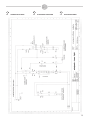
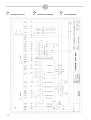
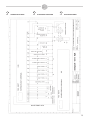
7.4 Schema elettrico ....................7-3
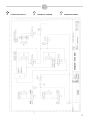
7.5 Schema pneumatico ...............7-7
7.6 Certificato di garanzia .............7-9
7.7 Condizioni di garanzia.............7-9
Capitolo 8. NORME
ECOLOGICHE
8.1 Scorie e residui ......................8-1
8.2 Smantellamento macchina......8-1
TABLE OF CONTENTS
Chapter 1. INTRODUCTION
1.1 Preface....................................1-1
1.2 Meaning and use of the
pictograms ..............................1-1
1.3 Identification of the machine ... 1-1
Chapter 2. DESCRIPTION AND
TECHNICAL DATA
2.1 Description of the machine......2-1
2.2 Technical data.........................2-2
Chapter 3. SAFETY
RULES
3.1 General precautions................3-1
3.2 Specific precautions ...............3-2
Chapter 4. INSTALLATION
4.1 Transportation and handling ...4-1
4.2 Connections ...........................4-2
Chapter 5. SETTING AT WORK
5.1 Reel carrier lock .....................5-1
5.2 Film loading ............................5-1
5.3 Adjustments ...........................5-4
5.4 Neck replacement ..................5-4
5.5 Envelope and “end”
length adjustment ..................5-5
5.6 Additional adjustments by
Eprom FGE186R.....................5-6
Chapter 6. USE OF THE
MACHINE
6.1 Control panel ..........................6-1
6.2 Defects and possible
remedies .................................6-3
6.3 Machine packaging
limits .......................................6-5
Chapter 7. MAINTENANCE
7.1 Precautions for maintenance
operations ..............................7-1
7.2 Wear and levels check............7-1
7.3 Machine cleaning ....................7-2
7.4 Electric diagram .....................7-3
7.5 Pneumatic diagram .................7-7
7.6 Certificate of guarantee...........7-9
7.7 Guarantee conditions..............7-9
Chapter 8. ENVIRONMENTAL
RULES
8.1 Waste and residuals ...............8-1
8.2 Machine dismantling ...............8-1
D
INHALT
Kapitel 1. EINLEITUNG
1.1 Vorwort ...................................1-1
1.2 Bedeutung und Anwendung
der Piktogramme ....................1-1
1.3 Identifizierung der Maschine ..1-1
Kapitel 2. BESCHREIBUNG UND
TECHNISCHE DATEN
2.1 Beschreibung der Maschine....2-1
2.2 Technische Daten....................2-2
Kapitel 3. SICHERHEITS-
BESTIMMUNGEN
3.1 Allgemeine Vorsichtsmaßnahmen ........
3-1
3.2 Spezifische Vorsichtsmaßnahmen 3-2
Kapitel 4. INSTALLATION
4.1 Transport und Umstellen ........4-1
4.2 Anschlüsse .............................4-2
Kapitel 5. INBETRIEBNAHME
5.1 Sperre Rollenträger ................5-1
5.2 Einsetzen der Folie ................5-1
5.3 Einstellungen ..........................5-4
5.4 Austausch des Kragens .........5-4
5.5 Einstellung von Tütenlänge
und “Endstück“ .......................5-5
5.6 Zusätzliche Einstellungen mit
Eprom FGE186R.....................5-6
Kapitel 6. ANWENDUNG
DER MASCHINE
6.1 Schaltfeld ...............................6-1
6.2 Störungen und
Behebung................................6-3
6.3 Verpackungsgrenzen
der Maschine ..........................6-5
Kapitel 7. WARTUNG
7.1 Vorsichtsmaßnahmen für
Wartungseingriffe ...................7-1
7.2 Kontrolle von Verschleiß und
Niveaus...................................7-1
7.3 Reinigung der Maschine .........7-2
7.4 Elektroschema .......................7-3
7.5 Pneumatikschema...................7-7
7.6 Garantieurkunde .....................7-9
7.7 Garantiebestimmungen...........7-9
Kapitel 8. UMWELT-
BESTIMMUNGEN
8.1 Abfälle und Restmaterial ........8-1
8.2 Verschrottung der Maschine ...8-1

I GB
1. INTRODUZIONE
1.1 PREFAZIONE
Avete acquistato una macchina dalle
caratteristiche e prestazioni ecceziona-
li e Vi ringraziamo per la preferenza
accordataci.
Il sistema di confezionamento MINI-
PACK è unico nel suo genere e si è
affermato nel mondo con la presenza
di oltre 50000 macchine operanti nel
campo dell’imballaggio e del confezio-
namento.
La validità del concetto tecnologico
oltre che la qualità dei componenti e
materiali impiegati nel processo pro-
duttivo e di collaudo sono la migliore
garanzia di un buon funzionamento e
affidabilità nel tempo.
A
VVERTENZA
Nell’interesse dell’utilizzatore delle
macchine, il presente manuale deve
essere attentamente letto:
- dal responsabile della manutenzio-
ne (prima dell’installazione)
- dall’operatore qualificato (prima
della messa in marcia).
1.2 SIGNIFICATO ED IMPIEGO
DEI PITTOGRAMMI
Pericolo generico: indica un
pericolo con rischio di infortu-
nio, anche grave, per l’utilizza-
tore
Apparati sotto tensione: indica
un pericolo di natura elettrica
con rischio di infortunio, anche
grave, per la persona esposta
Organi in movimento: indica il
pericolo di venire a contatto
con organi in movimento con
rischio di infortunio, anche
grave, per la persona esposta
Organi caldi: indica il pericolo
di ustioni con rischio di infortu-
nio, anche grave, per la per-
sona esposta
1.3 IDENTIFICAZIONE DELLA
MACCHINA
Per qualsiasi comunicazione con il
costruttore, citare sempre il modello
della macchina e il numero di matricola
indicati sulla targhetta applicata nella
parte posteriore della macchina.
1. INTRODUCTION
1.1 PREFACE
You have bought a machine of exceptio-
nal features and performances and we
wish to thank you for your preference.
The MINIPACK packaging system is
unique and well-established all over
the world with over 50,000 machines
working in the packaging field.
The validity of the technological con-
cept as well as the quality of the com-
ponents and materials used in the pro-
duction and test process are the best
guarantee for proper operation and
reliability all over the time.
W
ARNING
In the interest of the machine user, this
manual shall be carefully read by:
- the person in charge of maintenan-
ce (before installing)
- the qualified operator (before set-
ting at work).
1.2 MEANING AND USE
OF THE PICTOGRAMS
General danger: It shows a
danger involving the risk of a
serious accident for the user.
Live devices: It shows an
electrical danger involving the
risk of a serious accident for
the exposed person.
Moving members: It shows the
danger of coming into contact
with moving members, thus
involving the risk of a serious
accident for the exposed person.
Hot members: It shows the
danger of burning, thus invol-
ving the risk of a serious acci-
dent for the exposed person.
1.3 IDENTIFICATION OF THE
MACHINE
In any communication with the manu-
facturer, always specify the machine
model and serial number which may
be found on the label applied at the
back of the machine.
1-1
1. EINLEITUNG
1.1 VORWORT
Sie haben eine Maschine mit hervorra-
genden Eigenschaften und Leistungen
erworben und wir möchten Ihnen hier-
mit für Ihre Wahl danken.
Das Verpackungssystem MINIPACK ist
in seiner Art einzigartig und hat sich
weltweit mit über 50.000 in Betrieb
befindlichen Geräten auf dem
Verpackungssektor behauptet.
Die Gültigkeit des technologischen
Konzepts, wie auch die Qualität der
Komponenten und im Prüf- und
Produktionsprozess eingesetzten
Materialien sind die beste Garantie für
eine gute Funktion und langfristige
Zuverlässigkeit.
HINWEIS
Im Interesse des Anwenders der
Maschine sollte die vorliegende An-
leitung gut durchgelesen werden:
- vom Wartungsleiter (vor der In-
stallation)
- vom Fachbediener (vor der In-
betriebnahme).
1.2 BEDEUTUNG UND ANWEN-
DUNG DER PIKTOGRAMME
Allgemeine Gefahr: Zeigt eine
für den Bediener auch
schwerwiegende Unfallgefahr
an.
Gerät steht unter Strom: Zeigt
eine für die ausgesetzte
Person auch schwerwiegende
Unfallgefahr elektrischer Art an.
Bewegliche Maschinenteile:
Zeigt eine für die ausgesetzte
Person auch schwerwiegende
Unfallgefahr durch Berührung
mit beweglichen Maschinen-
teilen an.
Heiße Maschinenteile: Zeigt
eine für die ausgesetzte Person
auch schwerwiegende Ver-
brennungsgefahr durch heiße
Maschinenteile an.
1.3 IDENTIFIZIERUNG DER
MASCHINE
Bei Kontaktaufnahme mit dem Hersteller
sollten immer das Maschinenmodell und
die Kennummer angegeben werden, die
auf dem Schild auf der Maschinen-
rückseite angegeben sind.
D

I GB
2-1
2. DESCRIZIONE E
DATI TECNICI
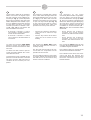
2.1 DESCRIZIONE DELLA
MACCHINA
La “Continua” è una imbustatrice oriz-
zontale automatica. Può essere utiliz-
zata inserendo le riviste manualmente
oppure utilizzando appositi caricatori
opportunamente sincronizzati.
All’uscita è consigliabile installare un
forno per la termoretrazione del film.
2. DESCRIPTION AND
TECHNICAL DATA
2.1 DESCRIPTION
OF THE MACHINE
“Continua” is an automatic horizontal
envelope machine. It may be used by
inserting the magazines manually or
by using the loaders which may be
properly synchronised.
It is recommended to install an oven
for thermoshrinking the film at the exit.
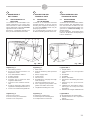
Legenda Fig. 1
1 Interruttore generale
2 Presa per interfacciamento con
dispositivi a monte
3 Cavo alimentazione elettrica
4 Quadro comandi
5 Zona bobina film
6 Volantino per la variazione della
lunghezza della busta
7 Coperchio zona saldatura trasver-
sale
8 Piedini di appoggio guide laterali
regolabili e relativi pomelli di blocco
9 Carter zona saldatura longitudinale
Legenda Fig. 2
10 Zona carico riviste
11 Zona scarico pacchi imbustati
12 Attacco aria compressa
Legend Fig. 1
1 Main switch
2 Plug for interfacing with upstream
devices
3 Electric supply cable
4 Control panel
5 Film reel area
6 Handwheel for changing the length
of the envelope
7 Transversal welding area cover
8 Feet supporting adjustable side
guides and relative lock knobs
9 Longitudinal welding area case
Legend Fig. 2
10 Magazines loading area
11 Packed parcels unloading area
12 Compressed air connection
Fig. - Abb. 1 Fig. - Abb. 2
6
5
4
79 12 8
10
12
11
3
2. BESCHREIBUNG UND
TECHNISCHE DATEN
2.1 BESCHREIBUNG
DER MASCHINE
“Continua“ ist ein horizontaler automa-
tischer Eintüter. Die Zeitschriften kön-
nen manuell oder mit Hilfe einer ent-
sprechend synchronisierten dafür vor-
gesehenen Ladevorrichtung ein-
geführt werden.
Es wird empfohlen, am Ausgang einen
Ofen für die Wärmeschrumpfung der
Folie zu installieren.
Legende Abb. 1
1 Hauptschalter
2 Schnittstelle mit anliegendem
Gerät
3 Stromkabel
4 Schaltfeld
5 Bereich Folienrolle
6 Handrad zur Einstellung der Tüten-
länge
7 Abdeckung des Querschweiß-
bereichs
8 Stellfüße für einstellbare Seiten-
führungen mit entsprechenden
Sperrstiften
9 Gehäuse des Längsschweißbereichs
Legend Abb. 2
10 Eingabebereich der Zeitschriften
11 Entnahmebereich der verpackten
Pakete
12 Druckluftanschluss
D

I GB
2-2
Ciclo di funzionamento (Fig. 1 e 2)
Il materiale da imbustare viene posi-
zionato sul caricatore con le guide
laterali opportunamente regolate. Il
caricatore introduce il materiale all’in-
terno del conformatore del film mentre
un dispositivo effettua la saldatura lon-
gitudinale.
Le buste avanzano appoggiate su un
tappeto folle, trascinato da 2 pinze
che, tramite un movimento alternato,
eseguono anche la saldatura e il taglio
tra le buste espellendole poi attraverso
l’apertura di uscita della macchina.
2.2 DATI TECNICI
- Tensione e frequenza: 220V / 50 Hz
- Potenza installata: 1000 Watt
- Assorbimento: 3,5 Amp
- Consumo aria: 40 litri/min. a 6 bar
- Produzione massima: 50 pezzi/min.,
formato A4 con film in polietilene da
25 micron
- Dimensioni materiale da imbustare:
minimo A6,
massimo A3, spessore massimo 12
mm
(34 mm in determinate condizioni)
- Film da utilizzare: spessore da 15 a
40 micron
- Larghezza massima della bobina:
650 mm
- Dimensioni della macchina:
2500x960x1100 mm
Operation cycle (Fig. 1 and 2)
The material which shall be put into an
envelope is placed on the loader after
the side guides have been properly
adjusted. The loader will put the mate-
rial inside the film regulator whereas a
device will provide for the longitudinal
welding.
The envelopes will move along an idle
belt dragged by 2 pliers which will
alternatively provide for welding and
cutting the envelopes as well as un-
load them through the opening at the
exit of the machine.
2.2 TECHNICAL DATA
- Voltage and frequency: 220V / 50 Hz
- Installed power: 1000 watt
- Input: 3.5 Amp
- Air consumption: 40 litres / min. at 6
bar
- Maximum production: 50 pieces /
min., A4 format with a 25 micron
polyethylene film
- Size of the material to be packed:
minimum A6,
maximum A3, maximum thickness
12 mm
(34 mm in special conditions)
- Film which shall be used: thickness
from 15 to 40 micron
- Maximum reel width: 650 mm
- Size of the machine:
2500x960x1100 mm
Betriebszyklus (Abb. 1 und 2)
Das zu verpackende Material wird auf
dem Belader mit entsprechend einge-
stellten Seitenführungen abgelegt. Der
Belader führt das Material in die Fo-
lienmeßvorrichtung ein während eine
Vorrichtung die Längsschweißung durch-
führt.
Die auf einem Laufband liegenden Tüten
werden durch 2 Zangen gezogen, die
abwechselnd auch das Schweißen und
Schneiden der anschließend aus der
Entnahmeöffnung der Maschine ausge-
führten Tüten durchführen.
2.2 TECHNISCHE DATEN
- Spannung und Frequenz: 220V /
50Hz
- Leistungsaufnahme: 1000 Watt
- Absorption: 3,5A
- Luftverbrauch: 40 l/min bei 6 bar
- Höchstproduktion: 50 St./min,
Format A4 mit Polyäthylenfolie zu
25 Micron.
- Größe des zu verpackenden
Materials:
Min. A6, max. A3, max. Stärke 12
mm
(34 mm unter bestimmten Be-
dingungen)
- Zu verwendende Folie: Stärke 15
bis 40 Micron
- Max. Rollenbreite: 650 mm
- Maschinenausmaße:
2500x960x1100 mm
D

I GB
3-1
3. NORME DI SICUREZZA
3.1 PRECAUZIONI GENERALI
Prima di operare sulla macchina per
interventi di regolazione, manutenzio-
ne e riparazione:
- mettere la macchina in sicu-
rezza premendo il tasto
“emergenza” posto sul pan-
nello di comando
- togliere tensione ruotando
l’interruttore principale sulla
posizione “0”
- togliere la spina di alimenta-
zione.
3. SAFETY RULES
3.1 GENERAL PRECAUTIONS
Before acting on the machine to adju-
st, service and repair it:
- put the machine in safe con-
ditions by pressing the
“emergency” button arran-
ged on the control panel
- power off the machine by
turning the main switch to
“0”
- remove the supply plug.
Fig. - Abb. 3
Sulla macchina dovrà operare solo
personale informato e formato.
- La rimozione di carter, por-
telli o paratie in condizioni di
non sicurezza può esporre
l’operatore/manutentore al
contatto con organi in movi-
mento, parti calde e appara-
ti sotto tensione.
- La rimozione dei dispositivi
di sicurezza, o comunque la
manomissione dei medesi-
mi, da parte dell’utilizzatore,
libera il fornitore da qualsia-
si responsabilità penale e
civile.
- Le stesse condizioni valgo-
no qualora venissero rimos-
se eventuali protezioni fis-
sate con viti, senza aver
prima provveduto all’arresto
della macchina.
3. SICHERHEITSBESTIMMUNGEN
3.1 ALLGEMEINE VORSICHTS-
MASSNAHMEN
Vor Inbetriebnahme der Maschine für
Einstellungen, Wartung und Re-
paraturen:
- die Maschine durch
Drücken der “Nottaste“ auf
dem Schaltfeld sichern;
- die Stromverbindung durch
Drehen des Hauptschalters
auf “0“ unterbrechen;
- den Stecker ziehen.
Only the personnel who have been
properly trained and informed may act
on the machine.
- The removal of cases,
doors or walls in unsafe
conditions may cause the
operator / maintenance man
to come into contact with
moving members, hot parts
and live devices.
- If safety devices are either
removed or tampered with
by the user, this will relieve
the supplier of any civil and
criminal liability.
- The same conditions will
apply if any protection which
may be fastened by the
screws is removed without
having stopped the machine
in advance.
Die Maschine darf nur durch geschul-
tes Fachpersonal bedient werden.
- Das Entfernen von Ge-
häusen, Klappen oder
Wänden unter unsicheren
Bedingungen kann den
Bediener/Wartungspersonal
mit beweglichen, heißen
oder unter Strom stehenden
Teilen in Kontakt bringen.
- Das Entfernen oder Mani-
pulieren von Sicherheits-
vorrichtungen seitens des
Bedieners enthebt den
Hersteller von jeglicher
straf-/zivilrechtlicher Ver-
antwortung.
- Gleiches gilt bei Entfernen
verschraubter Schutz-
vorrichtungen vor Abschal-
ten der Maschine.
D

I GB
3-2
3.2 PRECAUZIONI SPECIFICHE
Le pinze di saldatura a movimento
alternato non raggiungono mai una
temperatura elevata tale da conside-
rarsi pericolosa; fare tuttavia attenzio-
ne a non toccare con le dita la barra
saldante (o filo caldo) posta sotto il
profilo inferiore del becco saldante,
nascosta tra le 2 slitte premi film; per-
tanto prestare la massima attenzione
quando si opera nei pressi dei suddetti
organi perchè sussiste un potenziale
rischio di contatto accidentale con parti
molto calde.
Il dispositivo per la saldatura centrale
mantiene invece una temperatura ele-
vata per parecchi minuti dopo la disat-
tivazione della macchina e l'apertura
delle relative protezioni, pertanto pre-
stare la massima attenzione quando si
opera nei pressi del suddetto organo
perchè sussiste un potenziale rischio
di contatto accidentale con parti molto
calde (200°!!!)
- Si consiglia l’uso di guanti di
protezione.
Il ripristino della macchina in ciclo
automatico, implica tassativamente la
chiusura degli eventuali portelli di ispe-
zione.
Fig. - Abb. 4
D
3.2 SPECIFIC PRECAUTIONS
The welding pliers which will alternati-
vely move will never reach a high tem-
perature which may be considered as
dangerous. However, never touch the
welding rod (or the hot wire) arranged
beneath the lower profile of the weld-
ing burner and hidden between the 2
film pressing slides. Pay great atten-
tion when you are working in the proxi-
mity of the members above since there
is the potential risk of accidentally
coming into contact with very hot parts.
The device for the central welding will
keep a high temperature many minu-
tes after the machine has been dis-
abled and its protections have been
opened. Pay great attention when you
are working in the proximity of the
member above since there is the
potential risk of accidentally coming
into contact with very hot parts
(200°!!!).
- It is recommended to use
protection gloves.
The reset of the machine in automatic
mode will necessarily require the
inspection doors to be closed.
3.2 SPEZIFISCHE SICHERHEITS
MASSNAHNMEN
Die abwechselnd beweglichen
Schweißzangen erreichen niemals
eine als gefährlich zu betrachtende
Temperatur. Es sollte dennoch darauf
geachtet werden, dass die unter dem
unteren Profil der Schweißlasche, zwi-
schen den beiden Folienandruck-
schlitten, angebrachte Schweißleiste
(oder der heiße Draht) nicht mit den
Fingern berührt wird. Daher sollte bei
Arbeiten nahe dieser Bauteile höchste
Vorsicht herrschen, da Berührungs-
gefahr sehr heißer Elemente besteht.
Die mittlere Schweißvorrichtung besitzt
hingegen nach Abschalten der
Maschine und Öffnen der Schutz-
vorrichtungen für mehrere Minuten eine
sehr hohe Temperatur, weshalb höchste
Vorsicht herrschen sollte, wenn in der
Nähe dieser Bauteile Arbeiten durchzu-
rührungsgefahr mit Elementen, die bis
zu (200°C) heiß sind!
- Es wird das Tragen von Schutz-
handschuhen empfohlen.
Der Reset der Maschine in den auto-
matischen Zyklus erfolgt erst nach
Schließen eventuell geöffneter
Kontrollklappen.

I GB
3-3
La macchina è dotata di un microinter-
ruttore di sicurezza che segnala l'aper-
tura del coperchio zona saldatura tra-
sversale (7 - Fig. 1). Questo dispositivo
ferma ogni movimento della macchina
all'atto dell'apertura del suddetto coper-
chio. Per effettuare operazioni di messa
a punto della macchina, sul quadro
comandi è presente un selettore a chia-
ve (21 - Fig. 19) per l'esclusione del
micro interruttore di sicurezza.
- Ruotando il selettore a chiave
verso destra si esclude il funziona-
mento del microinterruttore.
- Ruotando il selettore a chiave
verso sinistra il microinterruttore è
in funzione.
La chiave del selettore NON DEVE
rimanere inserita nel quadro stesso
durante il normale funzionamento della
macchina.
La chiave non deve essere in posses-
so del personale addetto alla condu-
zione della macchina.
La chiave deve essere custodita da una
persona incaricata informata e formata
sui rischi che l'uso della macchina in
condizioni di non sicurezza può com-
portare.
The machine is complete with a safety
micro switch which will signal when the
transversal welding area cover is open
(7 - Fig. 1). This device will cause the
machine to stop when the cover above
is open. The key selector (21 - Fig. 19)
on the control panel shall be used to
override the safety micro switch and
provide for the set up of the machine.
- Turn the key selector to the right to
cause the micro switch to stop
working.
- Turn the key selector to the left to
cause the micro switch to start
working.
The selector key SHALL NOT remain
inside the panel while the machine is
normally running.
The key shall not be kept by the per-
sonnel who are responsible for the
operation of the machine.
The key shall be kept by a person who
is properly trained and informed about
the risks the use of the machine may
involve in unsafe conditions.
Die Maschine ist mit einem
Sicherheits-Mikroschalter ausgestattet,
der das Öffnen der Abdeckung im
Querschweißbereich anzeigt (7- Abb.
1). Diese Vorrichtung unterbricht bei
Öffnen der Abdeckung jede Bewegung
der Maschine. Zwecks Regulierung
der Maschine befindet sich auf dem
Schaltfeld ein Schlüsselschalter (21 -
Abb. 19) der den Sicherheitsschalter
überbrückt.
- Durch Drehen des Schlüssel-
schalters nach rechts wird die
Funktion des Mikroschalters deakti-
viert.
- Durch Drehen des Schlüssel-
schalters nach links wird die
Funktion des Mikroschalters akti-
viert.
Der Schlüssel DARF während dem
normalen Maschinenbetrieb NICHT im
Schaltfeld eingesteckt bleiben.
Der Schlüssel darf sich nicht im Besitz
des Maschinenbedieners befinden.
Der Schlüssel muss durch eine autori-
sierte und über die Risiken des
Maschinenbetriebs bei ungesicherter
Maschine informierte Person auf-
bewahrt werden.
D

I GB
4-1
4. INSTALLAZIONE
4.1 TRASPORTO E
MOVIMENTAZIONE
Peso della macchina: 400 kg circa
Procedere al sollevamento mediante
carrello elevatore di portata adeguata
(prestare attenzione al bilanciamento
della macchina e alle viti sporgenti
nella parte inferiore della scocca) o in
alternativa mediante imbracatura e
mezzo di sollevamento idoneo tramite
funi correttamente dimensionate e
provviste di ganci alle loro estremità.
Mettere lentamente in tensione le funi
facendo attenzione che non causino
danni e sollevare con precauzione la
macchina. Posizionare la macchina,
accertandosi che sia livellata sul pavi-
mento, in un ambiente adatto, privo di
umidità, materiali infiammabili, gas,
esplosivi.
Condizioni consentite negli ambienti in
cui è collocata la macchina:
- temperatura da - 5°C a + 40° C
- umidità da 30% a 90% senza con-
densazione.
4. INSTALLATION
4.1 TRANSPORTATION AND
HANDLING
Weight of the machine: about 400 kg
To lift the machine, use a lift truck
having an adequate capacity (make
sure the machine is properly balanced
and pay attention to the screws protru-
ding from the lower part of the body).
As an alternative provide for slinging
and use a hoist complete with ropes
which are properly dimensioned and
equipped with hooks at their end.
Tension the ropes slowly. Make sure
they will cause no damage. Lift the
machine with the greatest care. When
placing it, make sure it is levelled on
the floor and installed in a dry room
free of any inflammable material, gas
or explosive.
Permitted conditions in the rooms
where the machine is placed:
- temperature from –5°C to +40°C
- humidity from 30% to 90% without
any condensate.
D
4. INSTALLATION
4.1 TRANSPORT UND
UMSTELLEN
Maschinengewicht: zirka 400 kg
Die Maschine muss mit einem ange-
messenen Gabelstapler (auf das
Gleichgewicht der Maschine und die im
unteren Gehäusebereich hervorstehen-
den Schrauben achten), bzw. vertäut
durch ein angemessenes Kranfahrzeug
mit korrekt dimensionierten Seilen und
Haken angehoben werden.
Die Seile langsam anspannen und
darauf achten, dass beim Anheben die
Maschine nicht beschädigt wird. Die
Maschine an einem geeigneten trocke-
nen Ort frei von brennbarem und
explosionsgefährdetem Material oder
Gasen auf ebenem Boden abstellen.
Für den Standort der Maschine zuläs-
sige Raumbedingungen:
- Temperatur von –5°C bis +40°C
- Luftfeuchtigkeit von 30% bis 90%
ohne Kondensbildung.

I GB
4-2
D
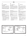
4.2 COLLEGAMENTI
Energia elettrica
Prima di effettuare il collegamento elet-
trico, verificare che la tensione di rete
corrisponda a quella indicata nella tar-
ghetta applicata sulla macchina e che la
messa a terra sia conforme alle norme
di sicurezza vigenti. In caso di dubbi
sulla tensione di rete, contattare l’ente
locale distributore dell’energia elettrica.
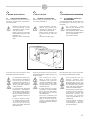
Aria compressa
Collegare, con una tubazione avente
diametro minimo di passaggio 6 mm e
con raccordo da 1/4” femmina, l’attacco
aria compressa (12 - Fig. 5) posto sul
lato uscita della macchina.
Apparecchiature di inserimento rivi-
ste automatiche
Connettere eventuali interfacce con
apparati posti a monte della macchina,
utilizzando la presa (2 - Fig. 6), tenendo
conto di quanto segue:
- filo marrone e filo bianco = contatto
NA che si chiude al passaggio dello
spintore. Per la regolazione del sin-
cronismo, spostare il sensore
magnetico, utilizzando la serie di fori
posti in circolo sul supporto in lamie-
ra, visibile in Fig. 21.
- filo viola e filo nero = cortocircuitare
per ottenere STOP.
Fig. - Abb. 5 Fig. - Abb. 6
2
12
4.2 CONNECTIONS
Electric energy
Before providing for the electrical con-
nection, make sure the mains voltage
will correspond to the voltage specified
by the label on the machine and that
grounding will comply with the safety
rules in force. In case of doubt about
the mains voltage, contact the local
electric energy supplier.
Compressed air
Connect the compressed air connec-
tion (12 - Fig. 5) at the exit of the
machine. Use a pipeline having a mini-
mum diameter of 6 mm. and a 1/4”
female union.
Equipment inserting the magazines
automatically
Connect any interface with a device
upstream the machine by using the
plug (2 - Fig. 6). Bear in mind as fol-
lows:
- brown wire and white wire = NO
contact closing when the pusher is
passing. To adjust the synchroni-
sm, move the magnetic sensor by
using the holes which are circularly
arranged on the sheet metal sup-
port (see Fig. 21).
- violet wire and black wire = short-
circuit to STOP.
4.2 ANSCHLÜSSE
Strom
Vor dem Stromanschluß überprüfen,
dass die Netzspannung mit den
Angaben auf dem Maschinenschild
übereinstimmt und eine den geltenden
Sicherheitsbestimmungen entspre-
chende Erdung vorhanden ist. Bei
Zweifeln hinsichtlich der
Netzspannung den lokalen
Strombetreiber ansprechen.
Druckluft
Mit einer Leitung mit min. 6 mm
Durchmesser und einem 1/4-Anschluss
verbinden; der Druckluftanschluss
befindet sich auf der Ausgangsseite
der Maschine (12 - Abb. 5).
Vorrichtungen zur automatischen
Zeitschrifteneingabe
Gegebenenfalls die Schnittstellen der
vor der Maschine installierten Gräte
anschließen (2 - Abb. 6), dabei auf fol-
gendes achten:
- brauner und weißer Draht = NA-
Kontakt der sich dem Schieber-
durchlauf schließt. Zur
Synchronisierung den Magnet-
sensor in den kreisförmig angeord-
neten Löchern im Blech versetzen,
siehe Abb. 21.
- violetter und schwarzer Draht =
Kurzschluß für STOP.

I GB
5-1
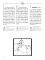
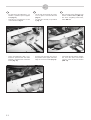
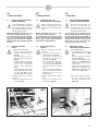
5. MESSA IN FUNZIONE
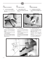
5.1 BLOCCO PORTA BOBINA
- Rimuovere la vite di fissaggio (A -
Fig. 7) dopo aver posizionato la
macchina.
Fig. - Abb. 7 Fig. - Abb. 8
5.2 CARICAMENTO DEL FILM
- Estrarre lo svolgitore (B - Fig. 7) e
riavvitare la vite di bloccaggio (A -
Fig. 7).
- Inserire la bobina sull’asse dello
svolgitore bloccandola con il cono
centratore (Fig. 8).
- Fare passare il film attorno al balle-
rino di comando dello svolgitore
(Fig. 9) come indicato anche sulla
targhetta adesiva.
Fig. - Abb. 9
A
B
D
5. SETTING AT WORK
5.1 REEL CARRIER LOCK
- Remove the fastening screw (A -
Fig. 7) after having placed the
machine.
5. INBETRIEBNAHME
5.1 SPERRE ROLLENTRÄGER
- Nach Ausstellen der Maschine die
Feststellschraube (A - Abb. 7) ent-
fernen.
5.2 FILM LOADING
- Extract the unwinder (B - Fig. 7)
and screw the locking screw again
(A - Fig. 7).
- Insert the reel on the axis of the
unwinder by locking it with the cen-
tering cone (Fig. 8).
- Let the film run around the control-
ling dandy roll of the unwinder (Fig.
9) as it is also shown by the adhe-
sive label.
5.2 EINSETZEN DER FOLIE
- Den Abwickler (B - Abb. 7) entneh-
men und die Feststellschraube (A -
Abb. 7) festschrauben.
- Die Rolle auf die Achse des
Abwicklers setzen und mit dem
konischen Zentrierer (Abb. 8)
blockieren.
- Die Folie um die Vordruckwalze
des Abwicklers (Abb. 9) führen,
wie auf dem Schild angegeben.

I GB
5-2
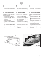
- Portare manualmente il film nella
parte superiore della macchina
(Fig. 10).
- Avvolgere in modo adeguato il
conformatore (Fig. 11).
Fig. - Abb. 10
Fig. - Abb. 11
D
- Manually move the film to the
upper part of the machine (Fig.
10).
- Wind the regulator as required
(Fig. 11).
- Die Folie von Hand in den oberen
Maschinenbereich führen (Abb.
10).
- Die Folienmeßvorrichtung entspre-
chend einstellen (Abb. 11).

I GB
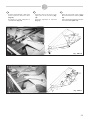
- Far passare il film attraverso i col-
letti fino a portarlo sopra il tappeto
folle (Fig. 12).
- Stendere accuratamente il film
come indicato in Fig. 13.
Fig. - Abb. 12
Fig. - Abb.13
- Tirare manualmente il film e con-
trollare la posizione dei due lembi
inferiore e superiore fino a formare
il tubo (Fig. 14).
Fig. - Abb. 14
5-3
D
- Let the film run through the necks
so as to place it over the idle belt
(Fig. 12).
- Lay the film carefully as specified
by Fig. 13.
- Die Folie durch die Öffnungen bis
auf das Laufband führen (Abb. 12).
- Die Folie sorgfältig ausbreiten,
siehe Abb. 13.
- Pull the film manually and check
the position of the upper and lower
edge so as to form a tube (Fig. 14).
- Von Hand die Folie ziehen und prü-
fen, dass die obere und untere
Lasche einen Schlauch bilden
(Abb. 14).

I GB
5-4
5.3 REGOLAZIONI
- Verificare l’esatta regolazione delle
guide laterali e gli spessori dei col-
letti.
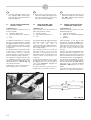
5.4 SOSTITUZIONE COLLETTO
C = Carter di protezione
Per effettuare il cambio del colletto,
procedere come segue:
1. Rimuovere il carter (C - Fig. 15).
2. Svitare le 2 viti (V - Fig. 16) di fis-
saggio del colletto (C).
3. Rimuovere il colletto (C - Fig. 16)
da sostituire.
4. Inserire il nuovo colletto.
5. Ricollocare in sede le viti (V - Fig.
16) ed avvitarle senza serrare.
6. Verificare la planarità del colletto e,
se necessario, ripristinarla agendo
sugli appositi grani (G - Fig. 16) di
regolazione.
7. Serrare le viti di fissaggio (V - Fig.
16).
Fig. - Abb. 15
Fig. - Abb. 16
C
V
C
G
V
G
D
5.3 ADJUSTMENTS
- Make sure the side guides and the
shims of the necks are properly
adjusted.
5.4 NECK REPLACEMENT
C = Protection case
To replace the neck, act as follows:
1. Remove the case (C - Fig. 15).
2. Unscrew the 2 screws (V - Fig. 16)
intended to fasten the neck (C).
3. Remove the neck (C - Fig. 16)
which shall be replaced.
4. Insert the new neck.
5. Rearrange the screws (V - Fig. 16)
and screw them without tightening
them firmly.
6. Check the levelness of the neck
and, if required, restore it by acting
on the adjusting dowels (G - Fig.
16).
7. Tighten the fastening screws firmly
(V - Fig. 16).
5.3 EINSTELLUNGEN
- Die korrekte Einstellung der
Seitenführungen und der Abstände
in den Kragen prüfen.
5.4 AUSTAUSCH DES KRAGENS
C = Schutzgehäuse
Den Kragen folgendermaßen austau-
schen:
1. Das Gehäuse entfernen (C - Abb.
15).
2. Die beiden Fixierschrauben (V -
Abb. 16) des Kragens (C) entfer-
nen.
3. Den auszutauschenden Kragen (C
- Abb. 16) entfernen.
4. Den neuen Kragen einsetzen.
5. Die Schrauben (V - Abb. 16) ein-
setzen und lose festschrauben.
6. Auf Ebenheit des Kragens achten
und gegebenenfalls an den beiden
Zapfen (G - Abb. 16) justieren.
7. Die Fixierschrauben (V - Abb. 16)
festschrauben.

I GB
5-5
8. Una volta sostituito il colletto, rego-
lare i deflettori (D) al livello appro-
priato del nuovo colletto tramite il
grano (R - Fig. 17).
5.5 REGOLAZIONE LUNGHEZZA
BUSTA E “CODA”
Legenda Fig. 18
La freccia indica la direzione in cui si
muove il prodotto.
“L” lunghezza della rivista
“X” spazio direttamente collegato a
“L”
“Y” coda
La lunghezza della busta "L", da 120 a
420 mm si regola ruotando il volantino
(6 - Fig.1); ruotando in senso antiorario
la busta si allunga, ruotando in senso
orario la busta si accorcia (vedi display
“Lunghezza”).
Questa operazione va eseguita mentre
la macchina è in funzione; se la mac-
china è ferma, ruotare il volantino
tenendo premuto il pulsante “Motore”
posto sul display (vedere capitolo 6).
Per regolare la lunghezza della coda
“Y”, modificare il valore "Coda" visua-
lizzato sul display (2 - Fig. 19) da 1 a 9
utilizzando tasti + e - (10 e 11- Fig. 19)
sul pannello operatore.
Aumentando il valore aumenta la lun-
ghezza della coda “Y” e viceversa.
Fig. - Abb. 17
Fig. - Abb. 18
R
D
R
L
Y
X
D
8. After having replaced the neck,
adjust the baffle plates (D) accord-
ing to the level of the new neck by
using the dowel (R - Fig. 17).
5.5 ENVELOPE AND “END”
LENGTH ADJUSTMENT
Legend Fig. 18
The arrow will show the direction in
which the product is moving.
“L” magazine length
“X” space directly related to “L”
“Y” end
Turn the handwheel (6 - Fig. 1) to adjust
the length of the “L” envelope, from
120 to 420 mm. Turn it
counterclockwise to lengthen the enve-
lope. Turn it clockwise to shorten it (see
the “Length” display).
This operation shall be carried out
while the machine is running. If the
machine is not working, turn the
handwheel while holding down the
“Motor” button on the display (see
chapter 6).
To adjust the length of the “Y” end,
change the “End” value on the display
(2 - Fig. 19) from 1 to 9 by using the +
and – keys (10 and 11 - Fig. 19) on
the operator’s panel.
Increase the value to increase the
length of the “Y” end and vice versa.
8. Nach Austausch des Kragens die
Deflektoren (D) durch den Zapfen
(R - Abb. 17) auf entsprechendes
Niveau einstellen.
5.5 EINSTELLUNG VON TÜTEN-
LÄNGE UND “ENDSTÜCK”
Legende Abb. 18
Der Pfeil zeigt die Direktion wo das
Produkt bewegt sich.
“L” Länge der Zeitschrift
“X” direkt mit “L“ zusammenhängende
Länge”
“Y” Endstück
Die Tütenlänge “L“ von 120 bis 420
mm wird am Handrad (6 - Abb. 1) ein-
gestellt; durch Drehen gegen den Uhr-
zeigersinn verlängert sich die Tüte,
durch Drehen im Uhrzeigersinn wird
die Tüte verkürzt (siehe Display
“Länge“).
Dieser Schritt wird durchgeführt wäh-
rend die Maschine in Betrieb ist; bei
Stillstand der Maschine das Handrad
drehen und dabei die Taste “Motor“ auf
dem Display drücken (siehe Kapitel 6).
Um die Länge des Endstücks “Y“ einzu-
stellen, den “auf dem Display abgebilde-
ten Wert “Endstück (2 - Abb. 19) mit
den Tasten + und – auf dem Schaltfeld
(10 und 11 - Abb. 19) von 1 bis 9 ein-
stellen.
Durch Erhöhen des Wertes wird die
Länge von „Y“ erhöht und umgekehrt.

I GB
5-6
5.6 REGOLAZIONI AGGIUNTIVE
CON EPROM FGE186E
1. E’ possibile regolare la temperatura
delle barre saldanti trasversali
(pinze) e del dispositivo di salda-
tura centrale (rotella) durante le
pause (stand-by) solo quando la
macchina si trova in posizione di
STOP e sul display FN compare la
“A”.
Per regolare la temperatura delle
pinze in stand-by:
- premere contemporaneamente i
tasti (8 e 16 - Fig. 19)
- selezionare il valore desiderato: da
1 a 9 con i tasti + e - sul display
SALD.TR.
N.B. La corretta regolazione della tem-
peratura in Stand-by delle pinze è
molto importante, perchè se è troppo
bassa, al riavviamento della macchina,
le buste tendono a rimanere attaccate.
Se è troppo alta, si rischia di bruciare
immediatamente il nastro verde.
Per regolare la temperatura della
rotella in stand-by:
- premere contemporaneamente i
tasti (8 e 16 - Fig. 19)
- selezionare il valore desiderato: da
0 a 20 con i tasti + e - sul display
SALD.LONG.
N.B. La corretta regolazione della tem-
peratura in Stand-by della rotella è
importante, perchè se è troppo bassa,
al riavviamento della macchina, la sal-
datura centrale sarà debole. Se è trop-
po alta, la rotella si sporca subito ed
invece di saldare taglia la busta.
2. E’ possibile attivare il ciclo di riscal-
damento veloce del dispositivo di
saldatura centrale (rotella)
Questo ciclo è attivabile solo quando la
macchina si trova in posizione di STOP
e sul display FN compare la “A”.
- Premere il pulsante S sul display
SALD.LONG.
- Premere il pulsante (8 - Fig. 19)
Il display lampeggia: il ciclo di riscalda-
mento è iniziato e dura 5 min; se
necessario ripetere l’operazione.
Per interrompere premere un pulsante
qualsiasi o avviare la macchina
(START).
Per conoscere la temperatura esatta
del dispositivo, utilizzare un termome-
tro portatile con fondo scala di 300°.
N.B. Questo ciclo è utile specialmente
all’inizio della produzione, quando la
macchina è fredda e permette di ridur-
re fino al 50% il tempo necessario per
riscaldare il dispositivo di saldatura
centrale.
D
5.6 ADDITIONAL ADJUSTMENTS
BY EPROM FGE186E
1. New possibility of regulating the tem-
perature of the transversal welding
rods (pliers) and of the central wel-
ding device (wheel) during the pau-
ses (stand-by). These adjustments
are only possible when the machine
is in a STOP position and “A”
appears on the FN display.
To regulate the temperature of the
pliers in the stand-by mode:
- press (No. 8 and No. 16 - Fig.
19) buttons at the same time
- select the value you wish: from 1 to
9 with the + and – keys on the
SALD.TR. display.
N.B. It is very important to regulate the
temperature of the pliers properly in
the stand-by mode. If it is too low, the
envelopes tend to remain attached to
each other when the machine is restar-
ted. If it is too high, the green tape may
immediately burn.
To regulate the temperature of the
wheel in the stand-by mode:
- press (No. 8 and No. 16 - Fig.
19) buttons at the same time
- select the value you wish: from 0 to
20 with the + and – keys on the
SALD.LONG.
N.B. It is important to regulate the tem-
perature of the wheel properly in the
stand-by mode. If it is too low, the
central welding will be weak when the
machine is restarted. If it is too high,
the wheel may get immediately dirty
and it will cut the envelope instead of
welding it.
2. Possibility of enabling the quick
heating cycle of the central wel-
ding device (wheel).
This cycle may be only enabled when
the machine is in a STOP position and
“A” appears on the FN display.
- Press the S button on the
SALD.LONG. display
- press the (No. 8 - Fig. 19) button
The display will flash on and off. The
heating cycle has been started and it
will last 5 min. If required, repeat the
operation.
To stop, press any button or start the
machine (START).
To learn the exact temperature of the
device, use a portable thermometer
with a 300° full scale.
N.B. This cycle is particularly useful at
the beginning of production, when the
machine is cold and it enables the
operator to reduce by max. 50% the
time required to heat up the central
welding device.
5.6 ZUSATZLICHE EINSTELLUNGEN
MIT EPROM FGE186E
1. Neue Möglichkeit der Temperatur-
einstellung der Querschweiß-
streben (Zangen) und der mittleren
Schweißvorrichtung (Rolle) wäh-
rend der Pause (Stand-by). Diese
Einstellungen sind nur möglich,
wenn die Maschine sich in STOP-
Position befindet und auf dem
Display FN “A“ erscheint.
Temperatureinstellung der Zangen
im Stand-by:
- gleichzeitig (Nr. 8 und Nr. 16 -
Abb. 19) drücken
- den gewünschten Wert wählen:
von 1 bis 9 mit den Tasten + und -
auf Display SALD.TR.
ANM. Die korrekte Temperatureinstel-
lung der Zangen im Stand-by ist sehr
wichtig, da bei einer zu niedrigen
Temperatur die Tüten bei Inbetrieb-
nahme der Maschine dazu neigen
aneinander festzukleben. Bei zu hoher
Temperatur läuft man sofort Gefahr
das grüne Band zu verbrennen.
Temperatureinstellung der Rolle im
Stand-by:
- gleichzeitig (Nr. 8 und Nr. 16 -
Abb. 19) drücken
- den gewünschten Wert wählen:
von 0 bis 20 mit den Tasten + und -
auf Display SALD.LONG.
ANM. Die korrekte Temperatureinstel-
lung der Rolle im Stand-by ist sehr wich-
tig, da bei einer zu niedrigen Temperatur
die mittlere Verschweißung bei
Inbetriebnahme der Maschine schwach
ist. Bei zu hoher Temperatur verschmutzt
die Rolle sofort und zerschneidet die
Tüte statt sie zu verschweißen.
2. Möglichkeit der Aktivierung des sch-
nellen Erhitzungszyklus der mittle-
ren Schweißvorrichtung (Rolle)
Dieser Zyklus ist nur möglich, wenn
die Maschine sich in STOP-Position
befindet und auf dem Display FN “A“
erscheint.
- die Taste S auf dem Display
SALD.LONG. drücken.
- die Taste (Nr. 8 - Abb. 19) drücken
Das Display blinkt: Der Erhitzungs-
zyklus wurde aktiviert und dauert 5
min.; gegebenenfalls den Schritt wie-
derholen.
Der Zyklus kann durch Drücken einer
beliebigen Taste oder Inbetriebnahme
der Maschine (START) abgebrochen
werden.
Um die genaue Temperatur der
Vorrichtung zu erhalten ein tragbares
Thermometer mit einem Skalenende
von 300°C verwenden.
ANM. Dieser Zyklus ist vor allem zu
Produktionsbeginn bei kalter Maschine
praktisch, da die Erhitzungsdauer der
mittleren Schweißvorrichtung um bis
zu 50% reduziert wird.

I GB
6-1
6. USO DELLA MACCHINA
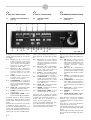
6.1 PANNELLO DI CONTROLLO
(Fig. 19)
Fig. - Abb. 19
Accendere la macchina tramite l’inter-
ruttore generale posto sul suo lato dx.
(1 - Fig. 1).
N° 1 FN mostra “J” = JOG (sono
state eseguite operazioni
manuali sulla macchina, oppure
non è ancora stata eseguita la
manovra di reset: premere
START una prima volta).
N° 1 FN mostra “A” = automatico
(macchina pronta per lavorare:
premere START una seconda
volta per iniziare il ciclo auto-
matico).
N° 2 CODA = quantità di film dietro il
prodotto (ogni numero corri-
sponde circa a 2,2 mm).
N° 3 LUNGHEZZA = lunghezza
busta (ogni numero corrisponde
circa a 1 cm) deve essere rego-
lata tramite volantino (vedere
capitolo 5.5).
N° 4 SALD. TR. = temperatura della
saldatura trasversale (pinze)
N° 5 PZ/MIN. = quantità di buste pro-
dotte per min.
N° 6 TOTAL./SALD. LONG. = conta-
pezzi. Premere “0” per resettarlo.
Premendo (N° 18), il display mostra la
temperatura della saldatura centrale
(ruota) valori indicativi non espressi in
gradi.
Pulsante (N° 8) = pulsante per resetta-
re allarmi: E5, E6, E7, E12, E13.
Se premuto simultaneamente con il pul-
sante (-) (N° 10): apre e chiude pinza A.
Se premuto simultaneamente con il pul-
sante (+) (N° 11): apre e chiude pinza B.
12 3 4 5 6 7
8
91011
12
13
14
15
16 17
18 19
20
21
D
6. USE OF THE MACHINE
6.1 CONTROL PANEL
(Fig. 19)
6. ANWENDUNG DER MASCHINE
6.1 SCHALTFELD
(Abb. 19)
Power on the machine by pressing the
main switch on its right side (1 - Fig.
1).
No. 1 FN shows “J” = JOG (manual
operations have been carried
out on the machine or reset has
not been performed yet: press
START once).
No. 1 FN shows “A” = AUTOMATIC
(the machine is ready to work:
press START once again to
start the automatic cycle).
No. 2 CODA = film quantity behind
the product (each number will
correspond to about 2.2 mm.).
No. 3 LUNGHEZZA = envelope
length (each number will cor-
respond to about 1 cm.), it shall
be adjusted by the handwheel
(see chapter 5.5).
No. 4 SALD. TR. = transversal weld-
ing temperature (pliers).
No. 5 PZ/MIN. = quantity of envelopes
produced per min.
No. 6 TOTAL./SALD. LONG. = piece
counter. Press “0” to reset it.
Press (No. 18) to display the central
welding (wheel) temperature, indicati-
ve values not expressed in degrees.
Button (No. 8) = button to reset
alarms: E5, E6, E7, E12, E13.
If pressed together with button (No.
10): it will open and close pliers A.
If pressed together with button (No.
11): it will open and close pliers B.
Die Maschine mit dem Hauptschalter
auf der rechten Seite einschalten (1 -
Abb. 1).
Nr, 1 FN zeigt “J” = JOG an (es wur-
den manuelle Schritte auf der
Maschine ausgeführt oder noch
keine Reset-Schritte durch-
geführt: erstmals START
drücken).
Nr. 1 FN zeigt “A” = Automatik an
(Maschine ist Betriebsbereit:
erneut START drücken um den
automatischen Zyklus einzulei-
ten).
Nr. 2 CODA = Folienlänge nach
Produkt (jede Ziffer entspricht
zirka 2,2 mm).
Nr. 3 LUNGHEZZA = Tütenlänge
(jede Ziffer entspricht zirka 1
cm), muss durch Handrad ein-
gestellt werden (siehe Kapitel
5.5).
Nr. 4 SALD. TR. = Querschweiß-
temperatur (Zangen).
Nr. 5 PZ/MIN. = Tütenzahl pro
Minute.
Nr. 6 TOTAL./SALD. LONG. = Zähler,
Reset durch Drücken von “0“.
Durch Drücken von (Nr. 18) zeigt das
Display die ungefähre mittlere
Schweißtemperatur (Rolle) nicht in
Grad an.
Taste (Nr. 8) = Taste für den Alarm-
Reset: E5, E6, E7, E12, E13.
Gleichzeitiges Drücken mit Taste (Nr.
10): Zange A wird geöffnet und gesch-
lossen.
Gleichzeitiges Drücken mit Taste (Nr.
11): Zange B wird geöffnet und gesch-
lossen.

I GB
6-2
Pulsanti (N° 12 e N° 14) sotto
“SALD.TR.” per aumentare e/o dimi-
nuire la temperatura della saldatura
orizzontale. Vedere la nota N. 1 a piè
pagina.
Pulsanti (N° 15 e N° 17) sotto
“PZ/MIN.” per aumentare e/o diminui-
re il numero di pezzi/min. prodotti.
Vedere la nota N. 2 a piè pagina.
Pulsanti (N° 19 e N° 20) = per aumen-
tare o diminuire la temperatura della
saldatura centrale. Tenere premuto il
pulsante (19) per resettare il totalizza-
tore.
Premere il pulsante motore (N° 9) per
azionare il motore a macchina ferma.
Pulsante start (N° 13) = premere una
prima volta per portare la macchina in
posizione di start. Premere una secon-
da volta per iniziare il ciclo di confezio-
namento.
Pulsante stop (N° 16) = per fermare il
ciclo di confezionamento.
Selettore (N° 21) = per attivare/disatti-
vare il fine corsa sicurezza dello spor-
tello superiore.
Pulsante (N° 7) = emergenza.
Nota N. 1 - utilizzare la minima tem-
peratura necessaria ad ottenere la sal-
datura della busta.
Utilizzare temperature superiori non
migliora il risultato ma deteriora preco-
cemente il nastro in gomma.
Nota N. 2 - la quantità di pezzi al
minuto ottimale dipende da: esperien-
za dell'operatore, dimensioni rivista, n.
di riviste da inserire, tipo di film utiliz-
zato.
D
Buttons (No. 12 and No. 14) below
“SALD.TR.” to increase and/or
decrease the horizontal welding tem-
perature. See note no. 1 at the bottom
of the page.
Buttons (No. 15 and No. 17) below
“PZ/MIN.” to increase and/or decrea-
se the number of pieces / min. pro-
ducts. See note no. 2 at the bottom of
the page.
Buttons (No. 19 and No. 20) = to
increase and/or decrease the central
welding temperature. Press button (19)
to reset the counter.
Press the motor button (No. 9) to start
the motor when the machine is not
running.
Start button (No. 13) = press it once to
put the machine in a start position.
Press it once again to start the packag-
ing cycle.
Stop button (No. 16) = to stop the
packaging cycle
Selector (No. 21) = to enable / disable
the safety limit stop of the upper door.
Button (No. 7) = emergency
Tasten (Nr. 12 und Nr. 14) unter
“SALD.TR.” erhöhen oder verringern
die horizontale Schweißtemperatur.
Siehe Anmerkung 1 am unteren
Seitenrand.
Tasten (Nr. 15 und Nr. 17) unter
“PZ/MIN.” erhöhen oder verringern die
pro Minute produzierte Stückzahl.
Siehe Anmerkung 2 am unteren
Seitenrand.
Tasten (Nr. 19 und Nr. 20) erhöhen
oder verringern die mittlere
Schweißtemperatur. Durch Drücken
von Taste (19) wird der Zähler zurück-
gesetzt.
Die Taste Motor (Nr. 9) drücken, um
den Motor bei abgeschalteter
Maschine zu starten.
Taste Start (Nr. 13) - erstmals drücken
um die Maschine in Startposition zu
bringen. Erneut drücken um den
Verpackungszyklus einzuleiten.
Taste Stop (Nr. 16) - unterbricht den
Verpackungszyklus.
Schalter (Nr. 21) - aktiviert/deaktiviert
den Sicherheits-Endanschlag der obe-
ren Klappe.
Taste (Nr. 7) = Nottaste.
Note No. 1 - use the minimum tempe-
rature required to weld the envelope.
If you use a higher temperature, this
will not improve the result but cause
the early deterioration of the rubber
tape.
Note No. 2 - the optimal quantity of
pieces per minute will depend upon
the operator’s experience, the dimen-
sions of the magazine, the number of
magazines which shall be inserted and
the type of film in use.
Anmerkung 1 - die geringste erforder-
liche Temperatur zum Tütenschweißen
verwenden.
Höhere Temperaturen verbessern das
Ergebnis nicht, vielmehr führen sie zu
einem früheren Verschleiß des gummi-
beschichteten Laufbands.
Anmerkung 2 - die optimale Menge
pro Minute ist von der Erfahrung des
Bedieners, Zeitschriftengröße, Zahl
einzutütender Zeitschriften und
Foliensorte abhängig.

I GB
6-3
6.2 INCONVENIENTI E
POSSIBILI RIMEDI
Sul display del pannello di comando
possono apparire dei codici di errore
che devono essere interpretati come
da seguente tabella:
“E” lampeggiante sul display
PZ/MIN. = Il passo della macchina
non è più sincronizzato
- La scheda elettronica invia regolar-
mente il comando di partenza alle
pinze ma queste non fanno in
tempo a ritornare sulla loro posizio-
ne di zero.
- La macchina produce ancora ma
non è più in grado di garantire la
misura esatta delle buste.
- Diminuire “PZ/MIN”.
- Controllare lo scorrimento dei car-
relli delle pinze.
- Controllare la pressione del mano-
metro di sinistra: da 4 a 5,5 bar.
E0 = Blocco saldatura
- Spegnere la macchina.
- Controllare eventuali cortocircuiti
sulle linee di alimentazione delle
barre saldanti.
- Controllare il trasformatore Ae B.
- Controllare la barra saldante di
pinza Ae pinza B.
- Controllare la molla di compensa-
zione del filo caldo di pinza A e
pinza B.
- Controllare la scheda (chiamare
assistenza).
E1 = Allarme su pinza A (il movimen-
to di apertura o chiusura della pinza A
è durato più di 2 secondi).
- Spegnere la macchina e controllare
l'aria compressa:
- il manometro di sinistra deve
segnare 2,2 bar
- qualche organo meccanico della
pinza si è bloccato
- una rivista di grosso spessore è
rimasta bloccata nella pinza
- uno dei 2 sensori magnetici si è
rotto
- il magnete inserito nella spalla della
pinza non si trova più nella sua
posizione corretta o non riesce ad
eccitare il sensore
- Chiamare assistenza.
D
6.2 DEFECTS AND
POSSIBLE REMEDIES
The display of the control panel may
show some error codes which shall be
interpreted according to the following
table:
“E” flashing on display “PZ/MIN.” =
the step of the machine is not syn-
chronized.
- The electronic board is regularly
sending the start command to the
sealing guns, but these have not
enough time to return to their “zero
position”.
- The machine keeps sealing, but
cannot guarantee the correct size
of the envelopes.
- Decrease “ PZ/MIN.”
- Verify the sliding of the sealing gun
trolleys.
- Check the pressure on the left
manometer: the correct range is
between 4 and 5,5 bar.
E0 = Welding lock
- Power off the machine.
- Check whether the supply lines of
welding rods have short-circuited.
- Check transformer Aand B.
- Check the welding rod of pliers A
and B.
- Check the hot wire balancing
spring of pliers Aand B.
- Check the board (call for assistan-
ce).
E1 = Alarm on pliers A (pliers A have
required more than 2 seconds to open
or close).
- Power off the machine and check
compressed air:
- the manometer on the left shall
show 2.2 bar
- a mechanical member of the
pliers has jammed
- a thick magazine has got stuck in
the pliers
- one of the two magnetic sensors
has broken down
- the magnet in the pliers shoulder
can no longer hold its correct
position or it can no longer ener-
gise the sensor
- Call for assistance.
6.2 STÖRUNGEN
UND BEHEBUNG
Auf dem Display des Schaltfelds kön-
nen Fehlercodes erscheinen, die
folgendermaßen zu verstehen sind:
“E” leuchtet auf LED-Anzeiger
“PZ/MIN.” = die Maschinenteilung
ist nicht mehr synchronisiert.
- Die Platine sendet regelmäßig den
Schweißzangen die Startsteuerung,
aber sie haben nicht Zeit genug, in
der Nullstellung zurückzukehren.
- Die Maschine läuft noch, kann aber
nicht die genaue Umschlagsgröße
gewährleisten.
- Der Wert “PZ/MIN.” reduzieren.
- Die Wagengleitung der Zangen
prüfen.
- Der Druck des linken Manometer
nachprüfen: er sollte zwischen 4
und 5,5 Bar liegen.
E0 = Schweißen blockiert
- Die Maschine abschalten
- Nach eventuellen Kurzschlüssen
der Stromversorgung der Schweiß-
leisten suchen
- Die Trafos A und B prüfen
- Die Schweißleisten der Zangen A
und B prüfen.
- Die Ausgleichsfeder des heißen
Drahts der Zangen Aund B prüfen.
- Die Schaltkarte prüfen (Hilfsdienst
benachrichtigen).
E1 = Alarm an Zange A (das Öffnen
und Schließen der Zange A dauert
mehr als 2 Sekunden).
- Die Maschine abschalten und die
Druckluft prüfen:
- das linke Manometer muss 2,2
bar anzeigen
- ein mechanisches Element der
Zange ist blockiert
- eine dicke Zeitung hat sich in der
Zange verklemmt
- einer der beiden Magnet-
sensoren ist beschädigt
- der in der Zangenseite einge-
setzte Magnet befindet sich auf
einer falschen Position und spri-
cht den Sensor nicht mehr an
- den Hilfsdienst benachrichtigen.
La pagina si sta caricando...
La pagina si sta caricando...
La pagina si sta caricando...
La pagina si sta caricando...
La pagina si sta caricando...
La pagina si sta caricando...
La pagina si sta caricando...
La pagina si sta caricando...
La pagina si sta caricando...
La pagina si sta caricando...
La pagina si sta caricando...
La pagina si sta caricando...
La pagina si sta caricando...
La pagina si sta caricando...
La pagina si sta caricando...
La pagina si sta caricando...
-
 1
1
-
 2
2
-
 3
3
-
 4
4
-
 5
5
-
 6
6
-
 7
7
-
 8
8
-
 9
9
-
 10
10
-
 11
11
-
 12
12
-
 13
13
-
 14
14
-
 15
15
-
 16
16
-
 17
17
-
 18
18
-
 19
19
-
 20
20
-
 21
21
-
 22
22
-
 23
23
-
 24
24
-
 25
25
-
 26
26
-
 27
27
-
 28
28
-
 29
29
-
 30
30
-
 31
31
-
 32
32
-
 33
33
-
 34
34
-
 35
35
-
 36
36


in altre lingue
- English: Minipack-Torre continua User manual
- Deutsch: Minipack-Torre continua Benutzerhandbuch
Documenti correlati

Altri documenti
-
SICK i17-S safety switch Istruzioni per l'uso
-
Cebora MIG 2035/MD JAGUAR DOUBLE PULSE Manuale utente
-
-
-
-
-
-
-
-
 Fort MICRO ECO Use And Maintenance Instructions
