Pioneer PRS-D1000M Manuale utente
- Categoria
- Amplificatori audio per auto
- Tipo
- Manuale utente


1
Before Using This Product ...................... 1
Product registration ............................................ 1
In case of trouble .............................................. 2
About This Product ............................................ 2
CAUTION ........................................................ 2
WARNING ........................................................2
Setting the Unit .......................................... 3
Terminal Cover ................................................ 3
Power Indicator ................................................ 3
Subsonic Select Switch .................................... 3
Bass Boost Control ............................................ 3
BFC (Beat Frequency Control) Switch ............ 3
MODE SELECT Switch .................................. 4
Gain Control ...................................................... 4
Cut Off Frequency Control for LPF .................. 4
Input Switch ...................................................... 4
POWER MODE Switch .................................... 4
Connecting the Unit .................................. 5
Connection Diagram ........................................ 6
Connecting the Power Terminal ........................ 7
Connecting the Speaker Output Terminals ...... 8
Using the Speaker Input .................................... 8
Connecting the Speaker Wires .......................... 9
Installation ................................................ 13
Example of installation on the floor mat
or on the chassis ...................................... 14
Replacing the terminal cover .......................... 14
Specifications .......................................... 15
Thank you for purchasing this PIONEER
product. Before attempting operation, be
sure to read this manual.
Private households in the 25 member
states of the EU, in Switzerland and
Norway may return their used electronic
products free of charge to designated col-
lection facilities or to a retailer (if you pur-
chase a similar new one).
For countries not mentioned above, please
contact your local authorities for the cor-
rect method of disposal.
By doing so you will ensure that your dis-
posed product undergoes the necessary
treatment, recovery and recycling and thus
prevent potential negative effects on the
environment and human health.
Product registration
Visit us at the following site:
Register your product. We will keep the
details of your purchase on file to help you
refer to this information in the event of an
insurance claim such as loss or theft.
If you want to dispose this
product, do not mix it with
general household waste. There
is a separate collection system
for used electronic products in
accordance with legislation that
requires proper treatment,
recovery and recycling.
Contents Before Using This Product

ENGLISH
ESPAÑOL
DEUTSCH
FRANÇAIS
ITALIANO
NEDERLANDS
êìëëäàâ
2
In case of trouble
When the unit does not operate properly,
contact your dealer or the nearest autho-
rized PIONEER Service Station.
About This Product
This product is a class D amplifier for the
subwoofer. If both L (left) and R (right)
channels are connected to the RCA input
of this product, output is mixed because
this product is a mono amplifier.
CAUTION
Never replace the fuse with one of greater
value or rating than the original fuse. Use
of an improper fuse could result in over-
heating and smoke and could cause dam-
age to the product and injury including
burns.
WARNING
• Always use the special red battery and ground
wire [RD-223] and [RD-222], which are sold sep-
arately. Connect the battery wire directly to the
car battery positive terminal (+) and the ground
wire to the car body. There is the risk of a fuse
burning out if only one of these is connected.
• Do not touch the amplifier with wet hands.
Otherwise you may get an electric shock. Also,
do not touch the amplifier when it is wet.
• For traffic safety and to maintain safe driving
conditions, keep the volume low enough so that
you can still hear normal traffic sound.
• Check the connections of the power supply and
speakers if the fuse of the separately sold battery
wire or the amplifier fuse blows. Detect the cause
and solve the problem, then replace the fuse with
another one of the same size and rating.
• To prevent malfunction of the amplifier and
speakers, the protective circuit will cut the power
supply to the amplifier (sound will stop) when an
abnormal condition occurs. In such a case, switch
the power to the system OFF and check the
connection of the power supply and speakers.
Detect the cause and solve the problem.
• Contact the dealer if you cannot detect the cause.
• To prevent an electric shock or short-circuit
during connection and installation, be sure to
disconnect the negative (–) terminal of the battery
beforehand.
• Confirm that no parts are behind the panel when
drilling a hole for installation of the amplifier. Be
sure to protect all cables and important equipment
such as fuel lines, brake lines and the electrical
wiring from damage.
• DO NOT allow amplifier to come into contact
with liquids due to, for example, the location
where the amplifier is installed. Electrical shock
could result. Also, amplifier and speaker damage,
smoke, and overheating could result from contact
with liquids. In addition, the amplifier surface
and the surface of any attached speakers could
become hot to the touch and minor burns could
result.

3
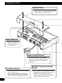
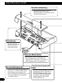
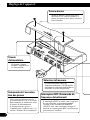
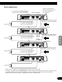
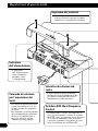
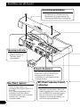
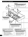
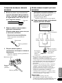
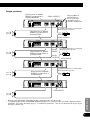
Setting the Unit
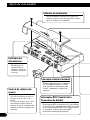
Power Indicator
The power indicator
lights when the power
is switched on.
Terminal Cover
Before setting up the unit, unfasten the
screws with a 4 mm hexagonal wrench
and remove the terminal cover.
Bass Boost Control
You can select a bass boost level from
0, 6, 9 and 12 dB.
For instruction of connecting the bass
boost remote control to the amplifier,
see the “Connection Diagram” section.
BFC (Beat Frequency Control)
Switch
BFC switch is on the bottom of the unit.
If you hear a beat while listening to an
MW/LW broadcast with your car
stereo, change the BFC switch using a
small standard tip screwdriver.
Subsonic Select Switch
The subsonic filter cuts inaudible
frequencies below 20 Hz to eliminate
unwanted vibrations and minimize
power loss.

ENGLISH
ESPAÑOL
DEUTSCH
FRANÇAIS
ITALIANO
NEDERLANDS
êìëëäàâ
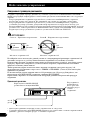
4
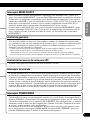
Gain Control
If the sound level is too low, even when the volume of the car stereo used along with this
power amplifier is turned up, turn gain control clockwise. If the sound distorts when the vol-
ume is turned up, turn the gain control counter-clockwise.
• When using with an RCA equipped car stereo (standard output of 500 mV), set to the NORMAL
position. When using with an RCA equipped Pioneer car stereo with max. output of 4 V or more,
adjust level to match the car stereo output level.
• If you hear too much noise when using the speaker input terminals, turn the gain control
counter-clockwise.
Input Switch
It is possible to input from a car stereo external output or a car stereo speaker output. Switch
the input switch before turning on the power. Since switching the input switch while the
power is on can cause a loud noise to be emitted from the speakers, the power is turned off
by a protection function. When using an external output, slide the switch to the left. For
connection instructions, see the “Connection Diagram” section. When using a speaker out-
put, slide the switch to the right. In this case, it is necessary to use the supplied speaker input
wire with RCA pin cord. For details, see the “Using the Speaker Input” section.
MODE SELECT Switch
You can select amplifier’s sync mode from MASTER, SYNC and SYNC INV. Set the MODE
SELECT switch to the MASTER position when using one amplifier only. When using synchronously
connecting two or more of these amplifiers in combination, set the first amplifier to MASTER, and set
the remaining amplifiers to SYNC or SYNC INV according to the manner in which they are connect-
ed. The only time the amplifier is switched to the SYNC INV mode is when amplifiers are synchro-
nously connected with the ex. bridge.
When switching to the SYNC INV mode, the seal over the MODE SELECT switch must be peeled off
and you can find SYNC INV switch. Peel off the seal after checking that connections are correct. See
the “Connecting the Speaker Wires” section for details on the MODE SELECT switch.
POWER MODE Switch
When using speakers with synthetic impeadance 2
Ω
to 8
Ω
, slide the switch to the right
(NORMAL). When using speakers with synthetic impeadance from 1
Ω
to less than 2
Ω
,
slide the switch to the left (HI-CURRENT). These settings are only used when using a sin-
gle amplifier. See the “Connecting the Speaker Wires” section when combining the use of
multiple amplifiers.
If the speaker impedance exceeds 2
Ω
(4
Ω
when using ex. bridge), although the POWER
MODE switch be may set to the HI-CURRENT position, setting to the NORMAL position
makes it possible to enjoy high power sound.
Cut Off Frequency Control for LPF
You can select a cut off frequency from 40 Hz to 240 Hz.

5
Connecting the Unit
CAUTION:
To prevent damage and/or injury
• Do not ground the speaker wire directly or con-
nect a negative (–) lead wire for several speakers.
• This unit is for vehicles with a 12-volt battery and
negative grounding. Before installing it in a recre-
ational vehicle, truck or bus, check the battery
voltage.
• If the car stereo is kept on for a long time while
the engine is at rest or idling, the battery may go
dead. Turn the car stereo off when the engine is at
rest or idling.
• If the system remote control wire of the amplifier
is connected to the power terminal through the
ignition switch (12 V DC), the amplifier will
always be on when the ignition is on— regardless
of whether the car stereo is on or off. Because of
this, the battery could go dead if the engine is at
rest or idling.
• DO NOT connect a subwoofer with a lower
impedance than specified in the “Connecting the
Unit” section. Amplifier damage, smoke, and
overheating could result from a non-specified
connection. The amplifier surface could also
become hot to the touch and minor burns could
result.
• Connect either of three subwoofers to the amplifi-
er; 1: a subwoofer with a 420 W or larger nomi-
nal input and an impedance 4 Ω, 2: a subwoofer
with a 600 W or larger nominal input and an
impedance 2 Ω or 3: a subwoofer with a 600 W
or larger nominal input and an impedance 1 Ω. If
the nominal input and impedance are out of the
above ranges, the subwoofer may catch fire, emit
smoke or become damaged.
• Install and route the separately sold battery wire
as far away as possible from the speaker wires.
Install and route the separately sold battery wire,
ground wire, speaker wires and the amplifier as
far away as possible from the antenna, antenna
cable and tuner.
• Cords for this product and those for other prod-
ucts may be different colors even if they have the
same function. When connecting this product to
another product, refer to the supplied Installation
manuals of both products and connect cords that
have the same function.
CAUTION
• Disconnect the negative (–) terminal of the bat-
tery to avoid the risk of short-circuit and damage
to the unit.
• Secure the wiring with cable clamps or adhesive
tape. To protect the wiring, wrap adhesive tape
around it where they lie against metal parts.
• Do not route wires where they will get hot, for
example where the heater will blow over them. If
the insulation heats up, it may become damaged,
resulting in a short-circuit through the vehicle
body.
• Make sure that wires will not interfere with mov-
ing parts of the vehicle, such as the gearshift,
handbrake or seat sliding mechanism.
• Do not shorten any wires. Otherwise the protec-
tion circuit may fail to work when it should.
• Never feed power to other equipment by cutting
the insulation of the power supply wire to tap
from the wire. The current capacity of the wire
will be exceeded, causing overheating.
• Never replace the fuse with one of greater value
or rating than the original fuse. Use of an improp-
er fuse could result in overheating and smoke and
could cause damage to the product and injury
including burns.

ENGLISH
ESPAÑOL
DEUTSCH
FRANÇAIS
ITALIANO
NEDERLANDS
êìëëäàâ
6
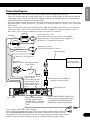
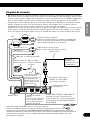
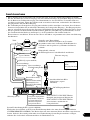
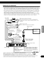
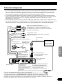
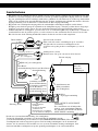
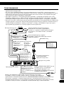
Connection Diagram
• This diagram shows connections using external output. Slide the input switch to the left.
• In the case of connecting the external output from a car stereo to an RCA input, use the jack used for full-
range output. This is because the LPF of the amplifier cannot be turned OFF. If this jack cannot be used,
connect the subwoofer output jack to the RCA input.
• When you connect with speaker output, connections defers from the diagram. For details, see the “Using
the Speaker Input” section. In either case, you need to set the input switch. For details, see the “Setting the
Unit” section.
• Always use the special red battery and ground wire ([RD-223] and [RD-222]), which are sold separately.
Connect the battery wire directly to the car battery positive terminal (+) and the ground wire to the car
body. There is the risk of a fuse burning out if only one of these is connected.
Fuse (40 A)
Car stereo with
RCA output jacks
External Output
Connecting wire with RCA
pin plugs (sold separately).
RCA input jack
System remote control wire (sold separately)
Connect the male terminal of this wire to the system remote control terminal of the car
stereo (SYSTEM REMOTE CONTROL). The female terminal can be connected to the
auto-antenna relay control terminal. If the car stereo does not have a system remote control
terminal, connect the male terminal to the power terminal through the ignition switch.
Speaker output terminal
See the “Connecting the
Speaker Wires” section for
speaker connection instruc-
tions.
Bass Boost Remote
Control Wire
Bass Boost
Remote Control
6 m
Jack for the bass boost
remote control
Connect this jack and
the bass boost remote
control with the bass
boost remote control
wire.
SYNC OUTPUT/SYNC INPUT jack
See the “Connecting the Speaker Wires”
section for SYNC OUTPUT/SYNC
INPUT jack connection instructions.
Fuse (30 A) × 3
Grommet
Special red battery wire
After making all other connections at the amplifier,
connect the battery wire terminal of the amplifier to
the positive (+) terminal of the battery.
Ground wire (black)
Connect to metal body or chassis.
[RD-223]
(sold separately)
[RD-222] (sold separately)

7
Connecting the Unit
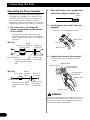
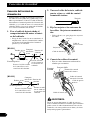
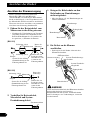
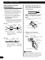
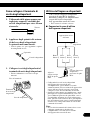
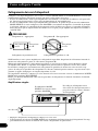
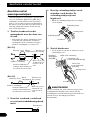
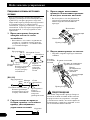
Connecting the Power Terminal
• Always use the special red battery and ground
wire ([RD-223] and [RD-222]), which are sold
separately. Connect the battery wire directly to
the car battery positive terminal (+) and the
ground wire to the car body. There is the risk of a
fuse burning out if only one of these is connected.
1. Pass the battery wire from the
engine compartment to the interior
of the vehicle.
• After making all other connections to the
amplifier, connect the battery wire terminal
of the amplifier to the positive (+) terminal of
the battery.
[RD-223]
[RD-222]
2. Twist the battery wire, ground wire
and system remote control wire.
3. Attach lugs to wire ends. Lugs not
supplied.
• Use pliers, etc., to crimp lugs to wires.
4. Connect the wires to the terminal.
• Fix the wires securely with the terminal
screws.
WARNING
Failure to securely fasten the battery wire to the ter-
minal using the terminal screws could cause the ter-
minal area to overheat and could result in damage
and injury including minor burns.
GND terminal
Power terminal
Battery wire
System remote
control terminal
System remote
control wire
Ground wire
Twist
Battery wire
Ground wire
Lug
Lug
Fuse (30 A)
Engine
compart-
ment
Interior of
the vehicle
Drill a 14 mm
hole into the
vehicle body.
Insert the O-ring rubber
grommet into the vehicle
body.
Positive terminal
Fuse (30 A)
Fuse (30 A)
Engine
compart-
ment
Interior of
the vehicle
Drill an 8 mm
hole into the
vehicle body.
Insert the O-ring rubber
grommet into the vehicle
body.
Positive terminal

ENGLISH
ESPAÑOL
DEUTSCH
FRANÇAIS
ITALIANO
NEDERLANDS
êìëëäàâ
8
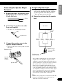
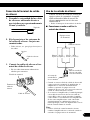
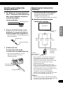
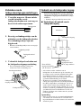
Connecting the Speaker Output
Terminals
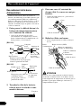
1. Expose the end of the speaker wires
using nippers or a cutter by about
10 mm and twist.
2. Attach lugs to speaker wire ends.
Lugs not supplied.
• Use pliers, etc., to crimp lugs to wires.
3. Connect the speaker wires to the
speaker output terminals.
• Fix the speaker wires securely with the termi-
nal screws.
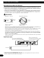
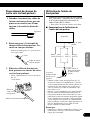
Using the Speaker Input
Connect the car stereo speaker output
wires to the amplifier using the supplied
speaker input wire with RCA pin cord.
• Slide the input switch to the right.
7 Connections when using the speaker
input
• As a result of connecting the car stereo speaker
output wire to the amplifier, the power of the
amplifier is turned on automatically when the car
stereo is turned on. It is not necessary to connect
the system remote control wire in this case.
• In the case the amplifier and head unit are con-
nected using a speaker input wire with RCA pin
cord, the amplifier power is only turned on when
one amplifier is being used. If two or more ampli-
fiers are synchronously connected in combina-
tion, connect the head unit and all of the ampli-
fiers with the system remote control wire.
Note:
• Connect the system remote control wire when the
power of the amplifier is not to be turned on
when the car stereo is turned on.
10 mm
Twist
Speaker wire
Lug
Speaker
output
terminal
Terminal screw
Speaker wire
Speaker
output
Car Stereo
Speaker input
wire with RCA
pin cord
To RCA input
jack of this unit.
White: Black: Black: Red:
Left + Left ≠ Right ≠ Right +

9
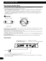
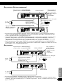
Connecting the Unit
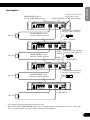
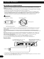
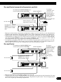
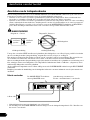
Connecting the Speaker Wires
Connect the speaker leads and set MODE SELECT switch and POWER MODE switch to suit the configura-
tion according to the figures shown below and the next page.
• When synchronously connecting two or more amplifiers in combination, only use these amplifiers. Do not
mix these amplifiers with other amplifiers.
• When synchronously connecting two or more amplifiers in combination, set the gain control, subsonic
select switch, cut off frequency control for LPF and bass boost control on the amplifier that has been set to
MASTER with the MODE SELECT switch. These settings are inactive when set on an amplifier set to
SYNC or SYNC INV.
CAUTION
Do NOT install or use this amplifier by wiring speakers rated at 2 Ω (or lower) in parallel to achieve a 1 Ω (or
lower) bridged mode (Diagram B).
Amplifier damage, smoke, and overheating could result from improper bridging. The amplifier surface could
also become hot to the touch and minor burns could result.
To properly install or use a bridged mode and achieve a 2 Ω load, wire two 4 Ω speakers in parallel with Left
+ and Right – (Diagram A) or use a single 2 Ω speaker.
If the synthetic impedance is from 2 Ω to less than 4 Ω, always make sure to set the POWER MODE switch to
the HI-CURRENT position.
In addition, refer to the speaker instruction manual for information on the correct connection procedure.
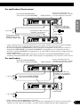
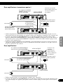
Single Amplifier
• Use speakers having an impedance from 1 Ω to 8 Ω.
• The setting of the POWER MODE switch varies according to the speaker impedance. See the “Setting the
Unit” section for details.
Diagram A - Proper
2 Ω Bridged Mode
4 Ω
Speaker
4 Ω
Speaker
Diagram B - Improper
1 Ω Bridged Mode
2 Ω
Speake
r
2 Ω
Speaker
MODE SELECT switch must
be in MASTER position.
Connect to a car stereo.
For details, see the “Connection Diagram”.
1 Ω to 8 Ω

ENGLISH
ESPAÑOL
DEUTSCH
FRANÇAIS
ITALIANO
NEDERLANDS
êìëëäàâ
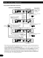
10
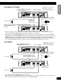
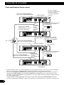
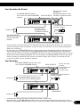
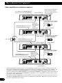
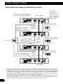
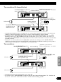
Two Amplifier (Ex. Bridge)
• Only use speakers having an impedance of 2 Ω to 16 Ω. In addition, in the case of connecting multiple
speakers with a bridge, check that the synthetic impedance is at least 2 Ω.
• The setting of the POWER MODE switch varies according to the speaker impedance. Slide the POWER
MODE switch to the HI-CURRENT position if the impedance is from 2 Ω to less than 4 Ω, or slide it to the
NORMAL position if the impedance is from 4 Ω to 16 Ω. The same setting is used for both amplifiers.
• When switching to the SYNC INV mode, the seal over the MODE SELECT switch must be peeled off and
you can find SYNC INV switch. Peel off the seal after checking that connections are correct.
Two Amplifier
• Use speakers having an impedance from 1 Ω to 8 Ω.
• The setting of the POWER MODE switch varies according to the speaker impedance. See the “Setting the
Unit” section for details. The same setting is used for both amplifiers.
MODE SELECT switch
must be in SYNC INV
position.
Connecting wire with RCA
pin plugs (sold separately).
Connecting
speaker wire
(sold separately).
MODE SELECT switch
must be in SYNC position.
MODE SELECT switch must
be in MASTER position.
Connect to a car stereo.
For details, see the
“Connection Diagram”.
2 Ω to 16 Ω
1 Ω to 8 Ω
1 Ω to 8 Ω
SYNC OUTPUT
MODE SELECT switch must
be in MASTER position.
Connect to a car stereo.
For details, see the
“Connection Diagram”.
Connecting wire with RCA
pin plugs (sold separately).
SYNC INPUT
SYNC OUTPUT
SYNC INPUT

11
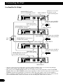
Connecting the Unit
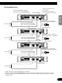
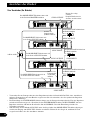
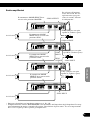
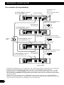
Four Amplifier (Ex. Bridge)
MODE SELECT switch
must be in MASTER position.
Connecting wire with RCA
pin plugs (sold separately).
MODE SELECT switch must
be in SYNC INV position.
Connect to a car stereo.
For details, see the
“Connection Diagram”.
MODE SELECT switch must be
in SYNC INV position.
MODE SELECT switch must
be in SYNC INV position.
Connecting wire with RCA
pin plugs (sold separately).
Connecting wire with RCA
pin plugs (sold separately).
Connecting speaker
wire (sold separately).
Connecting speaker
wire (sold separately).
SYNC OUTPUT
SYNC INPUT
SYNC OUTPUT
SYNC INPUT
2 Ω to
16 Ω
• Only use speakers having an impedance of 2 Ω to 16 Ω. In addition, in the case of connecting multiple
speakers with a bridge, check that the synthetic impedance is at least 2 Ω.
• The setting of the POWER MODE switch varies according to the speaker impedance. Slide the POWER
MODE switch to the HI-CURRENT position if the impedance is from 2 Ω to less than 4 Ω, or slide it to the
NORMAL position if the impedance is from 4 Ω to 16 Ω. The same setting is used for four amplifiers.
• When switching to the SYNC INV mode, the seal over the MODE SELECT switch must be peeled off and
you can find SYNC INV switch. Peel off the seal after checking that connections are correct.
SYNC OUTPUT
SYNC INPUT

12
ENGLISH
ESPAÑOL
DEUTSCH
FRANÇAIS
ITALIANO
NEDERLANDS
êìëëäàâ
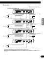
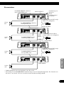
Four Amplifier
MODE SELECT switch
must be in MASTER position.
Connect to a car stereo.
For details, see the
“Connection Diagram”.
Connecting wire with RCA
pin plugs (sold separately).
Connecting wire with RCA
pin plugs (sold separately).
Connecting wire with RCA
pin plugs (sold separately).
MODE SELECT switch
must be in SYNC position.
MODE SELECT switch
must be in SYNC position.
MODE SELECT switch
must be in SYNC position.
1 Ω to 8 Ω
1 Ω to 8 Ω
1 Ω to 8 Ω
1 Ω to 8 Ω
SYNC OUTPUT
SYNC
INPUT
SYNC
OUTPUT
SYNC INPUT
• Use speakers having an impedance from 1 Ω to 8 Ω.
• The setting of the POWER MODE switch varies according to the speaker impedance. See the “Setting the
Unit” section for details. The same setting is used for four amplifiers.
SYNC OUTPUT
SYNC INPUT

13
Installation
CAUTION
• Do not install in:
—Places where it could injure the driver or pas-
sengers if the vehicle stops suddenly.
—Places where it may interfere with the driver,
such as on the floor in front of the driver’s
seat.
• Make sure that wires are not caught in the sliding
mechanism of the seats, resulting in a short-cir-
cuit.
• Confirm that no parts are behind the panel when
drilling a hole for installation of the amplifier.
Protect all cables and important equipment such
as fuel lines, brake lines and electrical wiring
from damage.
• Install tapping screws in such a way that the
screw tip does not touch any wire. This is impor-
tant to prevent wires from being cut by vibration
of the car, which can result in fire.
• DO NOT allow amplifier to come into contact
with liquids due to, for example, the location
where the amplifier is installed. Electrical shock
could result. Also, amplifier and speaker damage,
smoke, and overheating could result from contact
with liquids. In addition, the amplifier surface and
the surface of any attached speakers could
become hot to the touch and minor burns could
result.
• To ensure proper installation, use the supplied
parts in the manner specified. If any parts other
than the supplied ones are used, they may damage
internal parts of the amplifier, or they may
become loose causing the amplifier to shut down.
• Never replace the fuse with one of greater value
or rating than the original fuse. Use of an improp-
er fuse could result in overheating and smoke and
could cause damage to the product and injury
including burns.
CAUTION:
To prevent malfunction and/or injury
• To ensure proper heat dissipation of the amplifier,
be sure of the following during installation.
—Allow adequate space above the amplifier for
proper ventilation.
—Do not cover the amplifier with a floor mat or
carpet.
• DO NOT allow amplifier to come into contact
with liquids due to, for example, the location
where the amplifier is installed. Electrical shock
could result. Also, amplifier and speaker damage,
smoke, and overheating could result from contact
with liquids. In addition, the amplifier surface and
the surface of any attached speakers could
become hot to the touch and minor burns could
result.
• Do not install the amplifier on unstable places
such as the spare tire board.
• The best location for installation differs with the
car model and installation location. Secure the
amplifier at a sufficiently rigid location.
• Make temporary connections first and check that
the amplifier and the system operate properly.
• After installing the amplifier, confirm that the
spare tire, jack and tools can be easily removed.

14
ENGLISH
ESPAÑOL
DEUTSCH
FRANÇAIS
ITALIANO
NEDERLANDS
êìëëäàâ
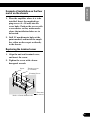
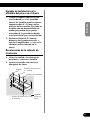
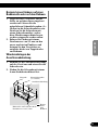
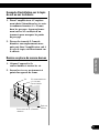
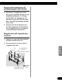
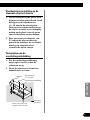
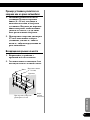
Example of installation on the floor
mat or on the chassis
1. Place the amplifier where it is to be
installed. Insert the supplied tap-
ping screws (4 × 18 mm) into the
screw holes. Push on the screws with
a screwdriver so they make marks
where the installation holes are to
be located.
2. Drill 2.5 mm diameter holes at the
point marked, and install the ampli-
fier, either on the carpet or directly
to the chassis.
Replacing the terminal cover
1. Align the unit and terminal cover,
and insert the screw.
2. Tighten the screw with a 4 mm
hexagonal wrench.
Drill a 2.5 mm diameter hole
Tapping-screws
(4 × 18 mm)
Floor mat
or chassis
Screw
Terminal Cover

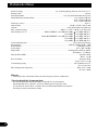
15
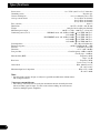
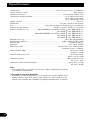
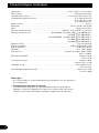
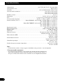
Specifications
Power source ........................................................................................................ 14.4 V DC (10.8 V to 15.1 V allowable)
Grounding system .......................................................................................................................................... Negative type
Current consumption ........................................................................................................ 39 A (at continuous power, 4 Ω)
Average current drawn* .......................................................................................................... 12 A (4 Ω for one channel)
20 A (2 Ω for one channel)
28 A (1 Ω for one channel)
Fuse (external) ........................................................................................................................................................ 40 A × 2
Dimensions ...................................................................................................................... 304 (W) × 56 (H) × 202 (D) mm
Weight .................................................................................................................... 3.0 kg (Leads for wiring not included)
Maximum power output ................................................................................ 800 W × 1 (4 Ω) / 1 200 W × 1 (1 Ω to 2 Ω)
Continuous power (14.4 V) ...................................... NORMAL mode: 4 Ω, 20 Hz to 240 Hz, 1.0% THD, 400 W × 1
2 Ω, 100 Hz, 1.0% THD, 600 W × 1
HI-CURRENT mode: 4 Ω, 20 Hz to 240 Hz, 1.0% THD, 150 W × 1
2 Ω, 100 Hz, 1.0% THD, 300 W × 1
1 Ω, 100 Hz, 1.0% THD, 600 W × 1
Load impedance ........................................................................................................................ 4 Ω (1 Ω to 8 Ω allowable)
Frequency response .......................................................................................................... 10 Hz to 240 Hz (+0 dB, –3 dB)
S/N ratio ........................................................................................................................................ 92 dB (IEC-A network)
Distortion .......................................................................................................................................... 0.5 % (10 W, 100 Hz)
Low pass filter ............................................................................................................ Cut off frequency: 40 Hz to 240 Hz
Cut off slope: –18 dB/oct
Subsonic filter (HPF) .............................................................................................................................. Frequency: 20 Hz
Slope: –18 dB
Bass boost ................................................................................................................................................ Frequency: 50 Hz
Level: 0 / 6 / 9 / 12 dB
Gain control .................................................................................................................................... RCA: 400 mV to 6.5 V
SP: 1.6 V to 26 V
Maximum input level / impedance ...................................................................................................... RCA: 6.5 V / 22 kΩ
SP: 26 V / 90 kΩ
Note:
• Specifications and the design are subject to possible modification without notice
due to improvements.
*Average current drawn
• The average current drawn is nearly the maximum current drawn by this unit
when an audio signal is input. Use this value when working out total current
drawn by multiple power amplifiers.

16
ENGLISH
ESPAÑOL
DEUTSCH
FRANÇAIS
ITALIANO
NEDERLANDS
êìëëäàâ

1
Antes de usar este producto .................... 1
Registro del producto ........................................ 1
En caso de desperfectos .................................... 2
Sobre este producto .......................................... 2
PRECAUCION ................................................ 2
ADVERTENCIA .............................................. 2
Ajuste de esta unidad .............................. 3
Cubierta de terminales ...................................... 3
Indicador de alimentación ................................ 3
Interruptor selector subsónico .......................... 3
Control de refuerzo de graves .......................... 3
Interruptor BFC
(Control de la frecuencia de batido) .......... 3
Interruptor MODE SELECT ............................ 4
Control de ganancia .......................................... 4
Control de frecuencia de corte para LPF .......... 4
Interruptor de entrada ........................................ 4
Interruptor POWER MODE .............................. 4
Conexión de la unidad .............................. 5
Diagrama de conexión ...................................... 6
Conexión del terminal de alimentación ............ 7
Conexión del terminal de salida de altavoz ...... 8
Uso de la entrada de altavoz .............................. 8
Conexión de los cables de altavoces ................ 9
Instalación ................................................ 13
Ejemplo de instalación en la alfombra
del piso o en el chasis .............................. 14
Recolocación de la cubierta de terminales ...... 14
Especificaciones .................................... 15
Muchas gracias por la adquisición de este
producto PIONEER. Antes de tratar de
operarlo, lea atentamente este manual.
Las viviendas privadas en los 25 estados
miembros de la UE, en Suiza y Noruega
pueden devolver gratuitamente sus produc-
tos electrónicos usados en las instalaciones
de recolección previstas o bien en las
instalaciones de minoristas (si adquieren
un producto similar nuevo).
En el caso de los países que no se han
mencionado en el párrafo anterior, pón-
gase en contacto con sus autoridades
locales a fin de conocer el método de elim-
inación correcto.
Al actuar siguiendo estas instrucciones, se
asegurará de que el producto de desecho se
somete a los procesos de tratamiento, recu-
peración y reciclaje necesarios, con lo que
se previenen los efectos negativos poten-
ciales para el entorno y la salud humana.
Registro del producto
Visítenos en el siguiente sitio:
Registre su producto. Conservaremos los
datos de su compra archivados para que
pueda consultar esta información en caso
de que deba efectuar un reclamo a la
compañía de seguros por pérdida o robo.
Si desea deshacerse de este
producto, no lo mezcle con
los residuos generales de su
hogar. De conformidad con la
legislación vigente, existe un
sistema de recogida distinto
para los productos
electrónicos que requieren un
procedimiento adecuado de
tratamiento, recuperación y
reciclado.
Contenido Antes de usar este producto

ENGLISH
ESPAÑOL
DEUTSCH
FRANÇAIS
ITALIANO
NEDERLANDS
êìëëäàâ
2
En caso de desperfectos
Si esta unidad no funciona correctamente,
póngase en contacto con su distribuidor o
con el Centro de Servicio PIONEER
autorizado más cercano.
Sobre este producto
Este producto es un amplificador para
altavoz de subgraves. Si ambos los canales
L (izquierdo) y R (derecho) se conectan a
la entrada RCA de este producto, la salida
se mezcla ya que este producto es un
amplificador monofónico.
PRECAUCION
No reemplace nunca el fusible por uno con
un valor de régimen mayor que el fusible
original. El uso de un fusible inadecuado
podría causar el sobrecalantamiento o
humo, así como podría causar daños al
producto y lesiones, incluyendo
quemaduras.
ADVERTENCIA
• Siempre utilice el cable de batería rojo especial y
los cables de tierra ([RD-223] y [RD-222]), ven-
didos separadamente. Conecte el cable de batería
directamente al terminal positivo de la batería del
vehículo (+) y el cable de tierra a la carrocería del
vehículo. Existe el riesgo de quemado del fusible
si se conecta solamente uno de ellos.
• No toque en el amplificador con las manos
mojadas. Caso contrario, usted puede llevar un
choque eléctrico. Igualmente, no toque en el
amplificador cuando esté mojado.
• Para seguridad del tráfico y para mantener condi-
ciones de conducción seguras, mantenga el volu-
men suficientemente bajo de manera que aun se
pueda escuchar el sonido del tráfico normal.
• Verifique las conexiones del suministro de
energía y altavoces para ver si el fusible del cable
de batería vendido separadamente o el fusible del
amplificador se queman. Detecte la causa y solu-
cione el problema, y reemplace el fusible con un
otro del mismo tamaño y régimen.
• Para evitar mal funcionamiento del amplificador
y altavoces, el circuito de protección cortará la
alimentación al amplificador (el sonido se
detendrá) cuando se produzca una situación anor-
mal. En tal caso, apague el sistema y verifique la
conexión de la alimentación y altavoces. Detecte
la causa y resuelva el problema.
• Contacte a su distribuidor si no puede detectar la
causa.
• Para evitar choques eléctricos o cortocircuitors
durante la conexión e instalación, asegúrese de
desconectar el terminal negativo (–) de la batería
antes de proceder.
• Confirme que ninguna parte quede detrás del
panel, cuando perfore un orificio para la insta-
lación del amplificador. Asegúrese de proteger
todos los cables y equipos importantes, tales
como líneas de combustibles, líneas de frenos y el
cableado eléctrico.
• NO permita que el amplificador entre en contacto
con líquidos debido a, por ejemplo, la locali-
zación donde el amplificador esté instalado. Esto
podría causar una sacudida eléctrica. El contacto
con líquidos también podría causar daños y
sobrecalentamiento al amplificador e altavoces.
Además, la superficie del amplificador y la super-
ficie de cualquier altavoz instalado también
podrían ponerse muy calientes al tacto, pudiendo
causar pequeñas quemaduras.

3
Ajuste de esta unidad
Indicador de
alimentación
El indicador de
alimentación se
ilumina cuando la
unidad se encuentra
activada.
Cubierta de terminales
Antes de montar la unidad, desapriete los
tornillos con una llave hexagonal de 4 mm y
quite la cubierta de terminales.
Interruptor BFC (Control de la
frecuencia de batido)
El interruptor BFC se encuentra en la parte inferior
de la unidad. Si se oye un batido durante la escucha
de una transmisión MW/LW con el equipo estéreo
de automóvil, cambie el interruptor BFC
utilizando un destornillador pequeño.
Control de refuerzo de
graves
Se puede seleccionar un nivel de
refuerzo de graves de 0, 6, 9 y
12 dB.
Para las instrucciones acerca de la
conexión del control remoto de
refuerzo de graves al amplificador,
consulte la sección “Diagrama de
conexión”.
Interruptor selector subsónico
El filtro subsónico corta las frecuen-
cias inaudibles inferiores a 20 Hz,
para eliminar las vibraciones inde-
seables y minimizar la pérdida de
potencia.
La pagina sta caricando ...
La pagina sta caricando ...
La pagina sta caricando ...
La pagina sta caricando ...
La pagina sta caricando ...
La pagina sta caricando ...
La pagina sta caricando ...
La pagina sta caricando ...
La pagina sta caricando ...
La pagina sta caricando ...
La pagina sta caricando ...
La pagina sta caricando ...
La pagina sta caricando ...
La pagina sta caricando ...
La pagina sta caricando ...
La pagina sta caricando ...
La pagina sta caricando ...
La pagina sta caricando ...
La pagina sta caricando ...
La pagina sta caricando ...
La pagina sta caricando ...
La pagina sta caricando ...
La pagina sta caricando ...
La pagina sta caricando ...
La pagina sta caricando ...
La pagina sta caricando ...
La pagina sta caricando ...
La pagina sta caricando ...
La pagina sta caricando ...
La pagina sta caricando ...
La pagina sta caricando ...
La pagina sta caricando ...
La pagina sta caricando ...
La pagina sta caricando ...
La pagina sta caricando ...
La pagina sta caricando ...
La pagina sta caricando ...
La pagina sta caricando ...
La pagina sta caricando ...
La pagina sta caricando ...
La pagina sta caricando ...
La pagina sta caricando ...
La pagina sta caricando ...
La pagina sta caricando ...
La pagina sta caricando ...
La pagina sta caricando ...
La pagina sta caricando ...
La pagina sta caricando ...
La pagina sta caricando ...
La pagina sta caricando ...
La pagina sta caricando ...
La pagina sta caricando ...
La pagina sta caricando ...
La pagina sta caricando ...
La pagina sta caricando ...
La pagina sta caricando ...
La pagina sta caricando ...
La pagina sta caricando ...
La pagina sta caricando ...
La pagina sta caricando ...
La pagina sta caricando ...
La pagina sta caricando ...
La pagina sta caricando ...
La pagina sta caricando ...
La pagina sta caricando ...
La pagina sta caricando ...
La pagina sta caricando ...
La pagina sta caricando ...
La pagina sta caricando ...
La pagina sta caricando ...
La pagina sta caricando ...
La pagina sta caricando ...
La pagina sta caricando ...
La pagina sta caricando ...
La pagina sta caricando ...
La pagina sta caricando ...
La pagina sta caricando ...
La pagina sta caricando ...
La pagina sta caricando ...
La pagina sta caricando ...
La pagina sta caricando ...
La pagina sta caricando ...
La pagina sta caricando ...
La pagina sta caricando ...
La pagina sta caricando ...
La pagina sta caricando ...
La pagina sta caricando ...
La pagina sta caricando ...
La pagina sta caricando ...
La pagina sta caricando ...
La pagina sta caricando ...
La pagina sta caricando ...
La pagina sta caricando ...
La pagina sta caricando ...
-
 1
1
-
 2
2
-
 3
3
-
 4
4
-
 5
5
-
 6
6
-
 7
7
-
 8
8
-
 9
9
-
 10
10
-
 11
11
-
 12
12
-
 13
13
-
 14
14
-
 15
15
-
 16
16
-
 17
17
-
 18
18
-
 19
19
-
 20
20
-
 21
21
-
 22
22
-
 23
23
-
 24
24
-
 25
25
-
 26
26
-
 27
27
-
 28
28
-
 29
29
-
 30
30
-
 31
31
-
 32
32
-
 33
33
-
 34
34
-
 35
35
-
 36
36
-
 37
37
-
 38
38
-
 39
39
-
 40
40
-
 41
41
-
 42
42
-
 43
43
-
 44
44
-
 45
45
-
 46
46
-
 47
47
-
 48
48
-
 49
49
-
 50
50
-
 51
51
-
 52
52
-
 53
53
-
 54
54
-
 55
55
-
 56
56
-
 57
57
-
 58
58
-
 59
59
-
 60
60
-
 61
61
-
 62
62
-
 63
63
-
 64
64
-
 65
65
-
 66
66
-
 67
67
-
 68
68
-
 69
69
-
 70
70
-
 71
71
-
 72
72
-
 73
73
-
 74
74
-
 75
75
-
 76
76
-
 77
77
-
 78
78
-
 79
79
-
 80
80
-
 81
81
-
 82
82
-
 83
83
-
 84
84
-
 85
85
-
 86
86
-
 87
87
-
 88
88
-
 89
89
-
 90
90
-
 91
91
-
 92
92
-
 93
93
-
 94
94
-
 95
95
-
 96
96
-
 97
97
-
 98
98
-
 99
99
-
 100
100
-
 101
101
-
 102
102
-
 103
103
-
 104
104
-
 105
105
-
 106
106
-
 107
107
-
 108
108
-
 109
109
-
 110
110
-
 111
111
-
 112
112
-
 113
113
-
 114
114


Pioneer PRS-D1000M Manuale utente
- Categoria
- Amplificatori audio per auto
- Tipo
- Manuale utente
in altre lingue
- English: Pioneer PRS-D1000M User manual
- français: Pioneer PRS-D1000M Manuel utilisateur
- español: Pioneer PRS-D1000M Manual de usuario
- Deutsch: Pioneer PRS-D1000M Benutzerhandbuch
- Nederlands: Pioneer PRS-D1000M Handleiding
Documenti correlati
-
Pioneer PRS-D1100M Manuale utente
-
Pioneer PRS-D1200M Manuale utente
-
Pioneer GM-3300T Manuale utente
-
-
-
-
-
-
-