
User Guide
For use with ProSYS 40,
and ProSYS 128

2 ProSYS User Guide
RTTE Declaration Of Conformity
Hereby, RISCO Group declares that this control panel (ProSYS 128,
ProSYS 40), with wired accessories (including cables) and wireless
accessories, is in compliance with the essential requirements and other
relevant provisions of Directive 1999/5/EC.
For the CE Declaration of Conformity please refer to our website:
www.riscogroup.com.
Compliance Statement
Hereby, RISCO Group declares that the ProSYS series of control
panels and accessories are suitable for use in systems designed to
comply with PD6662:2004 Security Grade 3, Environmental Class II.
(Security Grade 2 when using Wireless accessories).
The ProSYS series of control panels and accessories comply with the
relevant parts of the EN50131 series of standards. The ProSYS series
of control panels and accessories comply with DD243:2004
Important Notice
This manual is delivered subject to the following conditions and
restrictions:
Ê This manual contains proprietary information belonging to RISCO
Group. Such information is supplied solely for the purpose of
assisting explicitly and properly authorized users of the system.
Ê No part of its contents may be used for any other purpose,
disclosed to any person or firm or reproduced by any means,
electronic or mechanical, without the express prior written
permission of RISCO Group.
Ê The text and graphics are for the purpose of illustration and
reference only. The specifications on which they are based are
subject to change without notice.
Ê Information in this document is subject to change without notice.
Corporate and individual names and data used in examples
herein are fictitious unless otherwise noted.
Copyright © 2009 RISCO Group. All rights reserved.

ProSYS User Guide 3
Table of Contents
SUMMARY OF USER COMMANDS................................................. 6
CHAPTER 1: INTRODUCTION.........................................................9
Operating the System ............................................................. 10
The ProSYS Family .................................................................11
CHAPTER 2: YOUR KEYPAD........................................................12
The keypad............................................................................... 12
LED Indicators ......................................................................... 12
Power LED..........................................................................13
Set LED...............................................................................13
Ready LED..........................................................................14
Omit LED ............................................................................14
Fire LED..............................................................................15
Tamper LED........................................................................15
Keys..........................................................................................16
Numerical Keys...................................................................16
Control Keys .......................................................................16
Emergency Keys.................................................................17
Function Keys (A, B)...........................................................17
Quick Key Operation...........................................................18
LCD Status Display .................................................................18
LCD Blank Display ..................................................................18
CHAPTER 3: SETTING AND UNSETTING THE SYSTEM............ 19
Setting ......................................................................................19
Full Setting..........................................................................20
Part Setting.........................................................................22
Partition Setting ..................................................................23
Group Setting......................................................................25
Quick Setting.......................................................................26
Keyswitch Setting ...............................................................26

4 ProSYS User Guide
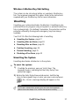
Wireless 4-Button Key Fob Setting.....................................27
Unsetting..................................................................................27
Unsetting the System..........................................................27
Unsetting After an Alarm.....................................................28
Resetting after an Alarm.....................................................29
Partition Unsetting ..............................................................30
Duress Unsetting................................................................31
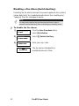
Disabling a Fire Alarm (Switch Auxiliary)............................32
CHAPTER 4: OMITTING A ZONE .................................................. 33
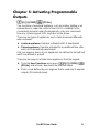
CHAPTER 5: ACTIVATING PROGRAMMABLE OUTPUTS .........35
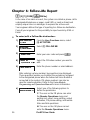
CHAPTER 6: FOLLOW-ME REPORT............................................36
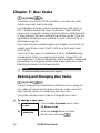
CHAPTER 7: USER CODES .......................................................... 38
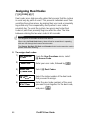
Defining and Changing User Codes...................................... 38
Deleting User Codes ............................................................... 40
User Authority Levels ............................................................. 41
Entering User Labels .............................................................. 42
Assigning Dual Codes ............................................................44
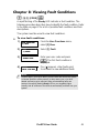
CHAPTER 8: VIEWING FAULT CONDITIONS .............................. 45
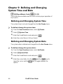
CHAPTER 9: DEFINING AND CHANGING SYSTEM TIME AND
DATE ...............................................................................................46
Defining and Changing System Time.................................... 46
Defining and Changing System Date ....................................46
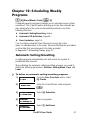
CHAPTER 10: SCHEDULING WEEKLY PROGRAMS.................. 47
Automatic Setting/Unsetting.................................................. 47
Defining a PO Activation Program ........................................ 49

ProSYS User Guide 5
Defining a User Limitation Program...................................... 51
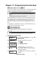
CHAPTER 11: PROGRAMMING FUNCTION KEYS ..................... 53
CHAPTER 12: PROXIMITY KEYPAD ............................................ 56
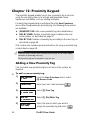
Adding a New Proximity Tag.................................................. 56
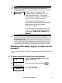
Deleting a Proximity Tag by the User Serial Number .......... 57
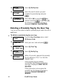
Deleting a Proximity Tag by the User Tag ............................58
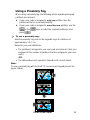
Using a Proximity Tag............................................................. 59
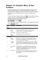
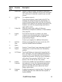
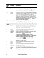
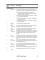
CHAPTER 13: COMPLETE MENU OF USER FUNCTIONS ......... 60
APPENDIX A: SYSTEM FAULTS................................................... 67
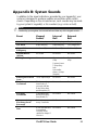
APPENDIX B: SYSTEM SOUNDS ................................................. 69
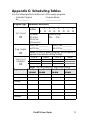
APPENDIX C: SCHEDULING TABLES .........................................71
APPENDIX D: TERMS AND DEFINITIONS ................................... 72

6 ProSYS User Guide
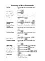
Summary of User Commands
Full Set
Hold the tag close to the keypad's keys
-OR-
Code>
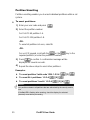
Part Setting
Code>
Group Setting Code>A/B/
Partition Full
Setting
Hold the tag close to the keypad's keys >
Partition No. >
-OR-
Code>
> Partition No. >
Partition Part
Setting
Code>
> Partition No. >
Partition Group
Setting
Code>A/B/ > Partition No. > A/B/C/D
System Unset
Hold the tag close to the keypad's keys
-OR-
Code>
Partition Unset
Hold the tag close to the keypad's keys >
Partition No. >
-OR-
Code>
> Partition No. >
Duress Unset
Duress Code >
Silence an Alarm
Hold the tag close to the keypad's keys
-OR-
Code>
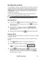
Omit Zones
>[1]>[1]>[Code] >[Zone No.]
Activate Output
>[2]>[1]>[Code] [PO No.]
Define Follow-Me
>[2]>[7]>[Code]
Enable Engineer
Installation
>[2]>[0]>[3]>[Code]> >
>
View Fault
>[3]>[1]>[Code]
>

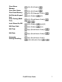
ProSYS User Guide 7
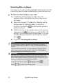
View Alarm
Memory
>[3]>[2]>[Code]>
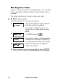
View Zone Status
>[3]>[4]>[Code]>
View Event Memory
>[3]>[5]>[Manager Code]>
Bell/Strobe/Keypad
Test
>[4]>[Code]> >[1]
Zone Testing (Walk
Test)
>[4]>[Grand Master Code]>
>[0]
Local Chime On/Off
>[4]>[Code]>
>[4]/[3]
Edit User Code
>[5]>[Code]>
>[1]
Edit Time
>[6]>[Grand Master Code]>
>[1]
Edit Date
>[6]>[Grand Master Code]>
>[2]
Automatic
Setting/Unsetting
>[6]>[Grand Master Code]>
>[5]>[Schedule No]>

8 ProSYS User Guide

ProSYS User Guide 9
Chapter 1: Introduction
Congratulations on your purchase of RISCO Group's ProSYS
Integrated Security System. The ProSYS has been designed to meet
PD6662 Grade 3 requirements and suits a wide range of commercial,
institutional and residential security applications.
The ProSYS includes the most advanced communication capabilities
for dual or triple-path communication to ARC’s. It consists of a variety
of sensors, detectors, and contacts placed throughout the premises by
your engineer. ProSYS is designed to recognize abnormal conditions
and inform the system of the status of any protected door, window,
hallway, room, or area. The Main Panel, which contains the system's
electronics and backup battery, functions in the background. For
purposes of security, it is recommended that it be installed out of sight.
You can place a household appliance or premises lighting under the
control of the ProSYS, where it can be conveniently turned on and off
automatically or by user command from any system keypad, or
wireless keyfob, described on page 35.
In addition, the ProSYS supports the following optional RISCO Group
devices:
Ê Advanced Communication Module (ACM) that enables the system
to operate over the IP network.
Ê GSM (AGM)/GPRS module which enables the system to
communicate over the GSM (AGM)/GPRS network, and also send
or receive SMS commands.
Ê Access Control, which enables integrating access control
capabilities into your security system.
Ê Digital Voice Module which enables you to receive voice
messages, operate the system from a remote phone, and listen- in
or speak to the premises.

10 ProSYS User Guide
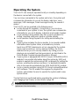
Operating the System
The ProSYS can easily be operated locally or remotely depending on
the devices connected to the system.
You can issue commands to the system and in turn, the system will
communicate information to you via its display, indicators, voice
messages, SMS messages, Email messages and by the sounds it
makes.
The ProSYS can be operated in the following ways:
Ê Locally through its keypad(s). Using its keys, you can issue
commands to your system. In turn, the system can communicate
information to you via its display, indicators and sounds it makes.
Ê Local operation using wireless key fobs or panic pendants for
setting, unsetting send panic alarm or activate outputs.
Ê Local operation using Keyswitch for setting and unsetting the
system.
Ê If your system includes the Voice module, it can provide audible
information about system status, and enable any remote,
touch-tone (DTMF) telephone to act as a keypad for the system.
Upon event occurrence, such as alarm activation, the Voice
module informs you of a security situation by calling you and
playing a pre-recorded Event announcement, as described in the
Voice Module Programming and Operations Manual
Ê If your system is equipped with RISCO Group's GSM(AGM)/GPRS
module it can provide information about the system by SMS and
enable to operate the system using SMS commands for setting the
system, unsetting the system and more. For detailed information
refer to the manual provided with the GSM (AGM)/GPRS module.
Ê Local or remote operation using RISCO Group’s upload/Download
(UD) software. The UD enables the engineer to program the
system, and enables the user to operate the system and to view
system status.
The first task to be performed before operating the system is Defining
and Changing User Codes, as described on page 38.
NOTE:
A certified serviceman should perform all repairs and maintenance including
replacement of the device battery.

ProSYS User Guide 11
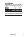
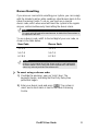
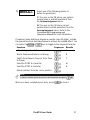
The ProSYS Family
This manual applies for both ProSYS 40 ProSYS 128 panels. The
following table, lists the number of features in each type of panel.
Feature ProSYS 40 ProSYS 128
Total Zones
8 - 40 8 - 128
User Codes
60 99
Programmable Outputs
6 - 38 6 - 70
Follow-Me Destinations
8 16
Maximum Keypads
12 16
Partitions
4 8
Scheduling Weekly
Programs
16 32

12 ProSYS User Guide
Chapter 2: Your Keypad
As a security system user, you will perform most operations using the
keypad. This section discusses the keypad's visual indicators and the
use of its keys.
The keypad’s type is LCD Proximity Keypad. It has the ability to
sense when a proximity key tag is near it thus providing the user with a
friendly and easy way to set or unset the security system (Refer to
Chapter 12, Proximity Keypad, page 56).
Each keypad in the system is assigned to a particular partition,
meaning that commands entered in a keypad are implemented only in
the partition to which it is assigned. For example, pressing the Quick
on a keypad assigned to partition 1 sets only partition 1.
The keypad
Each keypad in your system reports its status via its 6 LED (lighted)
indicators at the left, as described on page 12 or via messages
displayed on the LCD. Using its keys, you can enter commands to set
and unset the system, omit intrusion zones, report emergencies, and
so on, as described in the subsequent chapters of this manual.
NOTE:
For detailed information regarding the Touchscreen keypad, refer to the
ProSYS Touchscreen Keypad Instruction manual that is included with the
product.
LED Indicators
The six LED indicators found at the upper left provide typical system
indications, as discussed below. Some indicators have additional
functions, which are explained later on.
NOTE:
If required, setting the keypad to Hidden LCD mode can hide the system status.
In this mode, the Set, Ready and Omit LEDs do not function, and the LCD
displays ENTER CODE: After entering a valid user code, the system displays
the Normal Operation mode. One minute after the last operation, the system
automatically switches to Hidden LCD mode.

ProSYS User Guide 13
NOTE:
For detailed information regarding the LED indicators of the Touchscreen
keypad, refer to the ProSYS Touchscreen Keypad Instruction manual that is
included with the product.
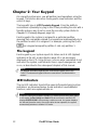
Power LED
The Power LED indicates system operation.
Condition Description
ON
The system is operating properly from mains (AC)
power or while the system is Set.
OFF
The system is inoperative due to lack of power
form mains (AC) and battery.
RAPID
FLASH
Indicates that mains power is not present for a
predefined time (consult your engineer).
NOTE:
Once the system is in Blank Display mode, the Power LED
will light steadily.
NOTE:
Once the system is set, a previously flashing or unlit Power LED will light
steadily.
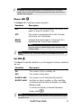
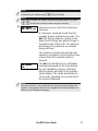
Set LED
The Set LED indicates whether or not the keypad’s intrusion detectors
are set.
Condition Description
ON
The system is fully or partially set.
OFF
The system is fully unset.
SLOW FLASH
The system is in its Exit Delay time period.
RAPID FLASH
Indicates an alarm condition or after unsetting
an alarmed system while the display is in Alarm
Memory mode.
To restore the display to Normal Operation
mode, press
.
NOTE:
Your engineer can disable the Set LED indication after a predefined time when
the system is set.

14 ProSYS User Guide
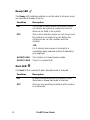
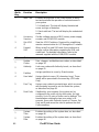
Ready LED
The Ready LED indicates whether or not the alarm’s intrusion zones
are secured and ready to be set.
Condition Description
ON
The system is unset and all the intrusion zones
are secure; the system is ready to be set and
there are no faults in the system.
OFF
One or more intrusion zones are not secure, and
the system is not ready to be set. Before the
system can be set, the condition must be
rectified.
-OR-
For 3 minutes when power is restored to a
completely down powered system (if defined by
your engineer).
SLOW FLASH The System is in User Function mode.
QUICK FLASH
There is a system fault.
Omit LED
The Omit LED is normally lit when Part Set mode is selected.
Condition Description
ON At least one intrusion zone is omitted, or Part
Set mode or Group Set mode is selected.
OFF
All zones are operating normally and the system
is in Set mode.

ProSYS User Guide 15
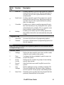
Fire LED
When lit, the Fire LED indicates that the system is experiencing a fire
alarm. When flashing, a problem has been detected on the fire circuit,
and must be serviced.
Condition Description
ON
A fire alarm or fire emergency is in progress or
has recently occurred.
OFF
All fire zones are operating normally.
FLASHING
A problem has been detected on the fire circuit
and it must be serviced.
Tamper LED
The Tamper LED indicates that a zone, a keypad, or an external
module has been tampered with and requires resetting. In some cases,
an Engineer code is required to restore the system to Normal
Operation mode.
Condition Description
ON
A zone, keypad, or an external module used by
the system has been physically disturbed or
tampered with. If unset without fixing the
problem, only the sound will be silenced.
NOTE:
The TAMPER LED shall NOT be on during tamper condition when the
system is SET.
If programmed by your engineer, resetting the TAMPER LED will require the
intervention an engineer.
OFF
There is no tamper alarm in the system.

16 ProSYS User Guide
Keys
The keys on the keypad can be used for a variety of functions. Each
key is explained below.
NOTE:
For detailed information regarding the keys of the Touchscreen keypad, refer to
the ProSYS Touchscreen Keypad Instruction manual that is included with the
product.
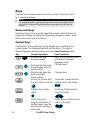
Numerical Keys
Numerical keys (0-9) are used to input the numeric codes that may be
required for setting, unsetting, and triggering emergency alarms, along
with several other special functions.
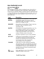
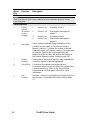
Control Keys
The functions of the other keys on the keypad vary according to the
current mode. The following table lists the functions of the keys in
Normal Operation mode and when using the User Functions menu:
Key Normal Operation User Functions
/
Activates the User
Functions mode.
Exits from the current menu
and returns to Normal
Operation mode.
/
Activates the Full mode,
Group Setting and Full
Quick Setting.
Changes data.
/
Activates the Night Set
mode and Night
Quick Setting.
Changes data.
Unsets the system after
the user code is entered.
Terminates commands and
confirms data to be stored.
Provides the system
status.
Scrolls up a list/moves the
cursor to the left.
Omits zones and
provides information on
omitted zones (must be
pressed after entering a
user code).
Scrolls down a list/moves the
cursor to the right.

ProSYS User Guide 17
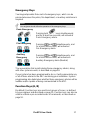
Emergency Keys
Your keypad provides three sets of emergency keys, which can be
pressed whenever the police, fire department, or auxiliary assistance is
required.
NOTE:
Your engineer should define the operation of the emergency keys.
Panic Emergency
/
Pressing both
keys simultaneously,
and for at least two seconds, will activate a
Panic Emergency alarm.
Fire Emergency
/
Pressing
and simultaneously, and
for at least two seconds, will activate a
Fire Emergency alarm.
Auxiliary
Emergency
/
Pressing
and simultaneously, and
for at least two seconds, will activate an
Auxiliary Emergency alarm.(Medical)
The annunciation that results during these emergency alarms, along
with other system sounds, is described on page 69.
If your system has been programmed to do so, it will communicate any
or all of these alarms to the ARC monitoring your installation. System
programming also determines whether these emergency alarms will be
audible and/or capable of being communicated to the ARC.
Function Keys (A, B)
By default, Function keys are used to set groups of zones, as defined
by your engineer and described on page 25. Function keys can also be
used to activate a pre-recorded series of commands, as described on
page 53.

18 ProSYS User Guide
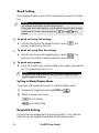
Quick Key Operation
The Quick Key Operation is a short effective way that helps you to
easily operate your system and quickly activate user functions, skipping
the user code. For example, to set the system, simply press the
key.
NOTE:
For quick key operation your engineer has to define quick key operation.
LCD Status Display
The LCD status display will vary depending on the number of partitions
in your system.
If your system is defined with only one partition, the LCD displays the
partition name, time and date.
If your system has 2 or 3 partitions, the LCD displays the system name,
date, time and the status of each partition. A status letter represents
the partition’s status, as follows:
SE: Partition is set NR: Partition Not Ready AL: Partition in Alarm
PS: Partition is set in Part set mode R: Partition Ready
LCD Blank Display
If defined by your engineer two minutes after the last keypad operation
the keypad will be disabled and the following display will appear on the
LCD:
Enter code:
_
Enter code:
_
To release the keypad and return to normal operation mode press:
[CODE] +
-or-
Present the Proximity Tag to Set/Unset the system.
NOTE:
During Blank Display mode the Ready LED indicates a fault in the system.

ProSYS User Guide 19
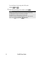
Chapter 3: Setting and Unsetting the
System
Setting
Setting your system enables its intrusion detectors to trigger an alarm
when violated.
You can set your system by code setting, in which you need to use
your user code, or you can use quick setting (without using a code)
NOTE:
If during code setting you enter a wrong user code, the keypad produces
three short beeps. Press [ ] [ ] quickly and re-enter the sequence
correctly.
Before setting your system check the Ready LED. If it is lit or flashing,
the system is READY to be set. If NOT the system is NOT ready to be
set. In this case, secure or omit the violated zone(s), and then proceed
Remember, fire protection and the protection offered by the keypad's
emergency keys are always available (if authorised by your engineer)
NOTE:
If defined by your enginner, your system can be defined to for Force
setting. This definition sets the system regardless of open zones when
using a keyswitch or automatic setting.
Note that force setting the system results in leaving partition(s) unsecured.
Your ProSYS offers the following kinds of settings:
Ê Full, page 20
Ê Partial, page 22
Ê Partition, page 23
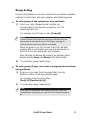
Ê Group, page 25
Ê Quick, page 26
Ê Blank Display, page 26

20 ProSYS User Guide
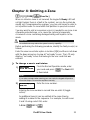
Full Setting
Full setting prepares all of the system's intrusion detectors to trigger an
alarm, if violated, and is used when leaving the premises empty.
NOTE:
Before setting the panel all open zones must be closed.
The installation company can program your system to full set using one
of the following:
Timed Exit: After entering your code, the alarm system will set after a
predefined exit time delay. This will help you to leave via the exit route
without interfering with the setting process.
NOTE:
The exit delay time can be extended once, to the time defined by the exit
delay, by pressing the key during the exit delay time.
Final Exit: After entering your code, the system will go to Full Set 10
seconds after the final exit door is closed.
Exit Terminator: After entering your code, the system will go to Full
Set 10 seconds after you press the Exit Terminator button (a push
button normally mounted outside the premises).
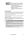
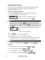
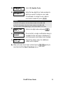
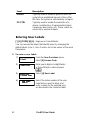
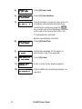
To Full Set:
1)
Check the Ready LED on your keypad. If it is constantly lit, the
system is READY to be set.
If the Ready LED is not lit the system is not ready to be set. In
this case, secure or omit the violated zone(s), as described on
page 22, and then proceed.
If the Ready LED is flashing, there are faults in the system
that need to be confirmed before continuing with the Full SET
process. (Ask your engineer if defined.)
2)
THE JONESES
THE JONESES
05:42 DEC 16 TUE
05:42 DEC 16 TUE
THE JONESES
THE JONESES
05:42 DEC 16 TUE
05:42 DEC 16 TUE
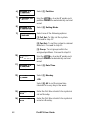
Hold the tag close to the keypad's keys or
Enter your user code and press
.
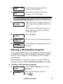
NOTE:
If required, all faults in the system should be confirmed to enable the setting
operation. Scroll down the list of fault/s using the key. At the end of
the list the following question will appear: « OVERIDE FLT? » Use the
key to toggle the option to Y and press .
La pagina sta caricando ...
La pagina sta caricando ...
La pagina sta caricando ...
La pagina sta caricando ...
La pagina sta caricando ...
La pagina sta caricando ...
La pagina sta caricando ...
La pagina sta caricando ...
La pagina sta caricando ...
La pagina sta caricando ...
La pagina sta caricando ...
La pagina sta caricando ...
La pagina sta caricando ...
La pagina sta caricando ...
La pagina sta caricando ...
La pagina sta caricando ...
La pagina sta caricando ...
La pagina sta caricando ...
La pagina sta caricando ...
La pagina sta caricando ...
La pagina sta caricando ...
La pagina sta caricando ...
La pagina sta caricando ...
La pagina sta caricando ...
La pagina sta caricando ...
La pagina sta caricando ...
La pagina sta caricando ...
La pagina sta caricando ...
La pagina sta caricando ...
La pagina sta caricando ...
La pagina sta caricando ...
La pagina sta caricando ...
La pagina sta caricando ...
La pagina sta caricando ...
La pagina sta caricando ...
La pagina sta caricando ...
La pagina sta caricando ...
La pagina sta caricando ...
La pagina sta caricando ...
La pagina sta caricando ...
La pagina sta caricando ...
La pagina sta caricando ...
La pagina sta caricando ...
La pagina sta caricando ...
La pagina sta caricando ...
La pagina sta caricando ...
La pagina sta caricando ...
La pagina sta caricando ...
La pagina sta caricando ...
La pagina sta caricando ...
La pagina sta caricando ...
La pagina sta caricando ...
La pagina sta caricando ...
La pagina sta caricando ...
La pagina sta caricando ...
La pagina sta caricando ...
-
 1
1
-
 2
2
-
 3
3
-
 4
4
-
 5
5
-
 6
6
-
 7
7
-
 8
8
-
 9
9
-
 10
10
-
 11
11
-
 12
12
-
 13
13
-
 14
14
-
 15
15
-
 16
16
-
 17
17
-
 18
18
-
 19
19
-
 20
20
-
 21
21
-
 22
22
-
 23
23
-
 24
24
-
 25
25
-
 26
26
-
 27
27
-
 28
28
-
 29
29
-
 30
30
-
 31
31
-
 32
32
-
 33
33
-
 34
34
-
 35
35
-
 36
36
-
 37
37
-
 38
38
-
 39
39
-
 40
40
-
 41
41
-
 42
42
-
 43
43
-
 44
44
-
 45
45
-
 46
46
-
 47
47
-
 48
48
-
 49
49
-
 50
50
-
 51
51
-
 52
52
-
 53
53
-
 54
54
-
 55
55
-
 56
56
-
 57
57
-
 58
58
-
 59
59
-
 60
60
-
 61
61
-
 62
62
-
 63
63
-
 64
64
-
 65
65
-
 66
66
-
 67
67
-
 68
68
-
 69
69
-
 70
70
-
 71
71
-
 72
72
-
 73
73
-
 74
74
-
 75
75
-
 76
76


Risco ProSYS 128 Manuale utente
- Tipo
- Manuale utente
- Questo manuale è adatto anche per
in altre lingue
- English: Risco ProSYS 128 User manual
Documenti correlati
-
Risco Agility Manuale utente
-
-
Ris lightsys RP432KP Manuale utente
-
-
Risco RP432KP02 Installation and User Manual
-
-
 RISCO Group ProSound Installation & Programming Manual
-
-
 RISCO Group WatchOUT Guida d'installazione
-


Altri documenti
-
PARADOX Esprit+ 642 Installer's Manual
-
Panasonic CZ-ESWC2 Manuale del proprietario
-
DSC PK5500 Guida d'installazione
-
-
Aritech CS-175-275-575 Series Manuale utente
-
Nice Automation MORX Manuale del proprietario
-
Motorola SDC1000 Istruzioni per l'uso
-
-
Pyronix Matrix 832 Programming Manual
-
Aritech CS350 Installation Instructions Manual