
4
rd
edition, February 2004
Additional
technical
information


3
Index
1. DMX Chart/Tabella funzionamento DMX 512 Pg. 4
2. Menu navigation map / Menu di navigazione rapida ,,. 8
3. Fan network / Mappatura delle ventole ,,. 9
4. Temperature sensor network / Posizione dei sensori di temperatura ,,. 9
5. Standard color wheel chart / Disposizione dei colori standard su ruota ,,. 10
6. Allignment value label / Etichetta valori di taratura motori ,,. 11
7. PCB assignment / Assegnazione schede ,,. 12
8. Updating electronic pcb software / Aggiornamento software schede elettroniche ,,. 16
9. Assembling Super narrow beam kit / Montaggio kit Super narrow beam ,,. 18
10. Electric diagrams / Schemi elettrici ,,. 22

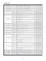
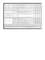
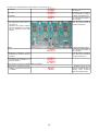
1.a DMX Chart
channel function type of control effect
1
x axis, base
movement (pan)
proportional
control of the movement of the beam of light by proportional
rotation of the pan motor of the fixture at the base
0-255 0% - 100%
2
x axis, fine base
movement (pan)
proportional
fine control of the movement of the beam of light by
proportional rotation of the pan motor of the fixture at the base
0-255 0% - 100%
3
y axis, yoke
movement (tilt)
proportional
control of the movement of the beam of light by proportional
rotation of the tilt motor of the fixture at the yoke
0-255 0% - 100%
4
y axis, fine yoke
movement (tilt)
proportional
fine control of the movement of the beam of light by
proportional rotation of the tilt motor of the fixture at the yoke
0-255 0% - 100%
step standard 0 - 10 0% - 4%
proportional variable speed from slow to fast 11 - 200 4% - 78%
step fast movement (ideal for positioning during programming) 201 - 255 79% - 100%
6 dimmer
proportional from closed to open 0 - 255 0% - 100%
step blackout closed (zap off) 0 - 9 0% - 4%
proportional synchronised strobing effect, from slow to fast 10 - 66 4% - 26%
step blackout open (zap off) 67 - 68 26% - 27%
proportional
sequenced pulse effect, slow closing, fast opening (Speed variable
from slow to fast)
69 - 125 27% - 49%
step blackout open (zap off) 126 - 127 49% - 50%
proportional
sequenced pulse effect, fast closing, slow opening (Speed variable
from fast to slow)
128 - 184 50% - 72%
step blackout open (zap off) 185 - 187 73% - 73%
proportional random strobe effect with variable speed from slow to fast 188 - 244 74% - 96%
step blackout open (zap off) 245 - 255 96% - 100%
step no effect 0 - 9 0% - 4%
proportional insertion of the framing shutter 0 - 100% 10 - 255 4% - 100%
step no effect 0 - 9 0% - 4%
proportional insertion of the framing shutter 0 - 100% 10 - 255 4% - 100%
step no effect 0 - 9 0% - 4%
proportional insertion of the framing shutter 0 - 100% 10 - 255 4% - 100%
step no effect 0 - 9 0% - 4%
proportional insertion of the framing shutter 0 - 100% 10 - 255 4% - 100%
step no effect 0 - 9 0% - 4%
proportional rotate framing wheel 0° - 90° 10 - 255 4% - 100%
13
control of beam
angle
proportional zoom - narrow to wide 0 - 255 0% - 100%
step no color (white beam) 0 - 5 0% - 2%
step color 1 6 - 15 2% - 6%
step color 2 16 - 25 6% - 10%
step color 3 26 - 35 10% - 14%
step color 4 36 - 45 14% - 18%
proportional
from color 4 to color 1 proportional positioning of the color
wheel
46 - 127 18% - 50%
proportional
rainbow effect, direction from color 1 to white rotation,
maximum to minimum
128 - 191 50% - 75%
proportional
rainbow effect, direction of rotation from white to color 1,
minimum to maximum
192 - 255 75% - 100%
16
cyan proportional proportional control of cyan colour from 0 to 100% 0 - 255 0% - 100%
17
magenta proportional proportional control of magenta colour from 0 to 100% 0 - 255 0% - 100%
18
yellow proportional proportional control of yellow colour from 0 to 100% 0 - 255 0% - 100%
19
CTO proportional
proportional control of the colour temperature (CTO) from 0 to
100%
0-255 0% - 100%
blackout, strobe
zap effect,
depending upon
channel 20
10
top framing
shutter
bottom framing
shutter
right framing
shutter
8
9
control of framing
shutter rotation
color wheel 1
(nearest to lamp),
color selection and
rotation
color wheel 2,
color selection and
rotation
percentage
5
7
movement speed
decimal
11
12
14
left framing shutter
15
4

channel function type of control effect
step no effect 0 - 10 0% - 4%
step
zap effect with adjustable flicker, flashing speed and mode
selection on channel 7, strobe
11 - 249 4% - 98%
step
Black-out of the beam of light during PAN/TILT movement of the
fixture or colour change
250 - 255 98% - 100%
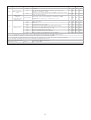
21
lamp power
control in
conjunction with
channel 22
proportional
adjust lamp power from minimum to maximum (~800W -
2000W) when channel 22 is between 121 - 195
0-255 0% - 100%
step park, no function 0 - 10 0% - 4%
step lamp off 11 - 32 4% - 13%
step pan and tilt reset (once only) 33 - 54 13% - 21%
step all motor reset exept dimmer, pan and tilt (once only) 55 - 76 22% - 30%
step all motor reset exept dimmer (once only) 77 - 98 30% - 38%
step reset of all the motors (once only) 99 - 120 39% - 47%
step lamp on, automated functions disabled 121 - 195 47% - 76%
step lamp on, lamp power adjustment auto-regulated 196 - 255 77% - 100%
Edition: 2
Data: 17/05/2003
Note 1: the maximum achievable lamp power is adjustable via the display function MAX.P (max power)
Note 2: The display panel may be used to disable the switching off of the lamp via DMX
Note 3: turning off the lamp and all the reset functions are delayed by 6 seconds to prevent accidental activation
Table name: DMX-512 functions
Note 4: the lamp on/off function can only be effected if an opposite level is set
lamp on/off, all
motors reset
20
decimal
percentage
Table number: 222
Projector: coemar iwash Flex
zap effect (varies
effect of channel 7
strobe)
22
5

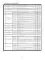
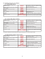
1.b Tabella Funzionamento DMX 512
canale funzione tipo di controllo effetto
1
asse X, movimento della
base
proporzionale
controllo del movimento del fascio di luce con rotazione
proporzionale del movimento in base
0-255 0% - 100%
2
asse X, movimento fine
della base
proporzionale
controllo del movimento fine del fascio di luce, con rotazione
proporzionale del movimento in base
0-255 0% - 100%
3
asse Y, movimento della
forcella
proporzionale
controllo del movimento del fascio di luce con rotazione
proporzionale del movimento in forcella
0-255 0% - 100%
4
asse Y, movimento fine
della forcella
proporzionale
controllo del movimento fine del fascio di luce, con rotazione
proporzionale del movimento in forcella
0-255 0% - 100%
livello unico standard 0 - 10 0% - 4%
proporzionale smorzamento regolabile, da lento a veloce 11 - 200 4% - 78%
livello unico veloce (ideale per posizione di programmazione) 201 - 255 79% - 100%
6 dimmer proporzionale regolazione graduale dell'intensità luminosa da 0 a 100% 0 - 255 0% - 100%
livello unico Otturatore chiuso (zap off) 0 - 9 0% - 4%
proporzionale
Effetto stroboscopico con frequenza di lampeggio variabile da
lenta a veloce
10 - 66 4%-26%
livello unico Otturatore aperto (zap off) 67 - 68 26% - 27%
proporzionale
effetto pulsato in sequenza, chiusura lenta, apertura veloce
(con regolazione frequenza della pulsazione da lenta a veloce)
69 - 125 27% - 49%
livello unico Otturatore aperto (zap off) 126 - 127 49% - 50%
proporzionale
effetto pulsato in sequenza, chiusura veloce, apertura lenta
(con regolazione frequenza della pulsazione da lenta a veloce)
128 - 184 50% - 72%
livello unico Otturatore aperto (zap off) 185 - 187 73% - 73%
proporzionale
Effetto stroboscopico con frequenza lampeggio variabile
casuale, non sincronizzata, da lenta a veloce
188 - 244 74% - 96%
livello unico Otturatore aperto (zap off) 245 - 255 96% - 100%
livello unico nessun effetto 0 - 9 0% - 4%
proporzionale
controllo proporzionale dell'inserimento nel fascio di luce
della ghigliottina paraluce
10 - 255 4% - 100%
livello unico nessun effetto 0 - 9 0% - 4%
proporzionale
controllo proporzionale dell'inserimento nel fascio di luce
della ghigliottina paraluce
10 - 255 4% - 100%
livello unico nessun effetto 0 - 9 0% - 4%
proporzionale
controllo proporzionale dell'inserimento nel fascio di luce
della ghigliottina paraluce
10 - 255 4% - 100%
livello unico nessun effetto 0 - 9 0% - 4%
proporzionale
controllo proporzionale dell'inserimento nel fascio di luce
della ghigliottina paraluce
10 - 255 4% - 100%
livello unico nessun effetto 0 - 9 0% - 4%
proporzionale
controllo proporzionale della rotazione nei 40° del gruppo
ghigliottine paraluce
10 - 255 4% - 100%
13 angolo del fascio di luce proporzionale
controllo proporzionale della dimensione del fascio di luce, da
stretto (spot) a largo (Flood)
0-255 0% - 100%
livello unico nessun colore, fascio bianco 0 - 5 0% - 2%
livello unico colore 1 6 - 15 2% - 6%
livello unico colore 2 16 - 25 6% - 10%
livello unico colore 3 26 - 35 10% - 14%
livello unico colore 4 36 - 45 14% - 18%
proporzionale da colore 4 a colore 1, posizionamento proporzionale 46 - 127 18% - 50%
proporzionale
effetto arcobaleno velocità decrescente, senso di rotazione da
colore 1 a bianco, altri a seguire
128 - 191 50% - 75%
proporzionale
effetto arcobaleno velocità crescente, senso di rotazione da
bianco a colore 4, altri a seguire
192 - 255 75% - 100%
selezione colori solidi
ruota colori 1 (la più
vicina alla lampada)
14
selezione colori solidi
ruota colori 2
15
11
12
rotazione ghigliottine
paraluce
ghigliottina paraluce
sinistra
8
ghigliottina paraluce
inferiore
ghigliottina paraluce
destra
9
10
decimale
percentuale
velocità del movimento
5
Otturatore, Strobo e
effetto zap,
dipendentemente dal
livello impostato sul
canale 20
7
ghigliottina paraluce
superiore
6

canale funzione tipo di controllo effetto
16 cyan proporzionale
controllo proporzionale della percentuale di colore cyan nel
fascio di luce; da 0 al 100%
0-255 0% - 100%
17 magenta proporzionale
controllo proporzionale della percentuale di colore magenta
nel fascio di luce; da 0 al 100%
0-255 0% - 100%
18 giallo proporzionale
controllo proporzionale della percentuale di colore giallo nel
fascio di luce; da 0 al 100%
0-255 0% - 100%
19 filtro di conversione proporzionale
controllo proporzionale della temperatura di colore del fascio
di luce
0-255 0% - 100%
livello unico nessun effetto 0 - 10 0% - 4%
livello unico
effetto zap, fliker a velocità regolabile, velocità lampeggio e
modo selezionabili da canale 7, strobo.
11 - 249 4% - 98%
livello unico
Black-out del fascio di luce mentre i movimenti PAN/TILT e/o i
colori delle 2 ruote variano di posizione
250 - 255 98% - 100%
21
potenza della lampada,
regola l'intensità
luminosa se il canale 22
è ad un livello compreso
tra 121 e 195
proporzionale
regolazione della potenza della lampada da minima a
massima,
0-255 0% - 100%
livello unico park, nessuna funzione 0 - 10 0% - 4%
livello unico lampada spenta 11 - 32 4% - 13%
livello unico reset di pan e tilt (solo una volta) 33 - 54 13% - 21%
livello unico reset di tutti i motori eccetto dimmer pan e tilt (solo una volta) 55 - 76 22% - 30%
livello unico reset di tutti i motori eccetto dimmer (solo una volta) 77 - 98 30% - 38%
livello unico reset di tutti i motori (solo una volta) 99 - 120 39% - 47%
livello unico lampada accesa, automatismi disabilitati 121 - 195 47% - 76%
livello unico lampada accesa, potenza lampada auto-regolata 196 - 255 77% - 100%
Edizione: 2
Data: 17/05/2003
decimale
percentuale
Nota 2: Agendo sul pannello display può essere impedito lo spegnimento della lampada via DMX
Nota 3: lo spegnimento lampada e la funzione di reset hanno un ritardo di 6 secondi per prevenire attivazioni accidentali
Nota 4: la funzione lampada on/off può subire variazioni solo se viene impartito un comando di valore opposto
Nome della tabella: funzionamento DMX 512
effetto zap e diapositiva
varia l'effetto del canale
7 strobo
20
accensione lampada,
reset dei motori
22
NOTA 1: la massima potenza raggiungibile della lampada è regolabile da display, funzione MAX.P (max power)
Tabella numero: 222
Proiettore: coemar iwash Flex
7

8
2. Menu Navigation Map / Menu di Navigazione Rapida
not
implemented
non
implementato
only if lamp off
solo se la lampada è spenta
CW
CCW
PDIR
TDIR
LAMP
MAX.P.
PROT
DISP
LED
RESE
DFSE
NO.AL
T 1
T 2
CH01
CH22
58C
58C
10
255
FAN1
FAN2
FA13
00
FUNC
MEAS
MODE
DMX
ALRM
TEMP
DMIN
RATE
HOUR
TEST
SFAN
LAMP
PFC
S.VER
ID
SENS
24
LIFE
LIFS
UNIT
100
589
1230
PAN
TILT
COL1
COL2
FRLE
PC.LE
DEMO
999
–999
ALIG
PAN
TILT
SH-R
SH-L
KN-U
KN-R
KN-D
KN-L
KNRO
COL1
COL.2
FR.LE
PCLE
CYAN
YEL
MAG
CTO
SAVE
UNDO
0000
SURE
01B2
02B2
AMS
RE.LA
01B4
02B4
04B4
S AB2
SAB 4
BALR
B.ALR
NO.AL
BUCK
000
AOO1
A023
A023
<
menu
>
<
enter
>
<
enter
>
<
enter
>
<
enter
>
<
enter
>
<
enter
>
<
enter
>
<
enter
>
<
enter
>
<
enter
>
<
enter
>
<
enter
>
<
enter
>
<
enter
>
<
more
>
+
<
menu
>
SENS menu appears only if
you power up the fixture with
the <more> button depressed.
Il menu SENS appare solo
se alimentate l'apparecchio
con il tasto <more> premuto.
<+
/
–>
<+
/
–>
<+
/
–>
<+
/
–>
<+
/
–>
<+
/
–>
<+
/
–>
<
enter
>
<
enter
>
<
enter
>
<
enter
>
<
enter
>
<
enter
> <
enter
>
<
enter
>
<
enter
>
<
enter
>
<
enter
>
<
enter
>
<
enter
>
<
enter
>
<+
/
–>
<
enter
>
<+
/
–>
<
+
/
–
>
<+
/
–>
<+
/
–>
<+
/
–>
<+
/
–>
<
enter
>
<
enter
>
<
enter
>
<
enter
>
<
enter
>
<
enter
>
<
enter
>
<
enter
>
<
enter
>
<
enter
>
<
enter
>
F.VER
OP.SY
01,01
01,00
<
enter
>
<
enter
>
800
ZAP
OFF
<
enter
>
ON
OFF
<
enter
>
ON
OFF
NUMBERS
SURE
<
enter
> <
enter
>
0.1
to
255
PAN
TILT
DIMM
KN-U
KN-D
KN-L
KN-R
KF.RO
ZOOM
COL 1
COL 2
CYAN
MAG
YEL
CTO
<
enter
>
<
enter
>
<
enter
>
<
enter
>
<
enter
>
<
enter
>
<
enter
>
<
enter
>
<
enter
>
<
enter
>
<
enter
>
<
enter
>
<
enter
>
<
+
/
–
>
<
enter
>
<
more
>
<+
/
–>
<
enter
>
<+
/
–>
<+
/
–>
<
enter
>
<
enter
>
<
enter
>
<
enter
>
<+
/
–>
<+
/
–>
<+
/
–>
CW
CCW
<
enter
>
<+
/
–>
<
enter
>
<
enter
>
STRD
ON
<
enter
>
<+
/
–>
<
enter
>
<
enter
>
<
enter
>
<+
/
–>
<+
/
–>
<
enter
>
<
enter
>
<
enter
>
<
enter
>
<
enter
>
<
enter
>
<
enter
>
<
enter
>
<
enter
>
<
enter
>
<
enter
>
<
enter
>
<
enter
>
<
enter
>
<
enter
>
<
enter
>
<
enter
>
<
enter
>
1250
to
2000
<
enter
>
<
enter
>
ON
OFF
SAFE
<
enter
>
<
enter
>
<
enter
>
<
enter
>
<+
/
–>
<+
/
–>
ON
AUTO
DARK
AUTO
DOWN
UP
<
enter
>
<
enter
>
<
enter
>
<
enter
>
<+
/
–>
<
enter
>
<
enter
>
<
enter
>
<
enter
>
<+
/
–>
A001
COUNTDOWN
<
enter
>
ATTENZIONE: l'uso improprio di queste funzioni
può causare errori fatali all'apparecchio.
Solo tecnici specializzati possono accedere
a questi settaggi funzionali
WARNING: Improper use of these functions
can cause fixture errors.
Refer to trained service technicians.
IWASH Flex edition / versione: 23/05/2003
<
enter
>
20%
30%
<
enter
>

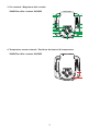
3. Fan network / Mappatura delle ventole
4. Temperature sensor network / Posizione dei sensori di temperatura
IWASH Flex edition / versione: 24/06/2003
T1
T2
11
12
20
IWASH Flex edition / versione: 24/06/2003
3
4
5
6
1
2
9
10
8
7
13
14
15
9

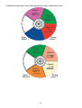
5. Standard color wheel chart / Disposizione dei colori standard su ruota
Color
Wheel 2
Color 4
Color 4
VT 198/V
VT 198/V
Green
Green
Color Filter
Color Filter
Color 3
Color 3
VT 198/RS
VT 198/RS
Pink
Pink
Color Filter
Color Filter
Color 1
Color 1
VT 198/AM
VT 198/AM
Amber
Amber
Color Filter
Color Filter
Color 2
Color 2
FC 026
FC 026
CTB Filter
CTB Filter
3200/5600K
3200/5600K
Ruota
colori 2
Color
Wheel 1
Color 2
Color 2
VT 198/V1
VT 198/V1
Sea Green
Sea Green
Color Filter
Color Filter
Color 1
Color 1
VT 198/VL
VT 198/VL
Violet
Violet
Color Filter
Color Filter
Color 3
Color 3
VT 198/R
VT 198/R
Red
Red
Color Filter
Color Filter
Color 4
Color 4
VT 198/B
VT 198/B
Blue
Blue
Color Filter
Color Filter
Ruota
colori 1
10

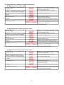
6. Allignment value label / Etichetta valori di taratura motori
Default Value
Valori di default settati da coemar sull’apparecchio
Costumer Version 1/ Costumer Version 2/ Costumer Version 3/
Versione Cliente 1 Versione Cliente 2 Versione Cliente 3
PAN
TILT
SH-R
SH-L
KN-U
KN-R
KN-D
KN-L
KNRO
COL1
COL.2
FR.LE
PCLE
CYAN
YEL
MAG
CTO
Param.
Alignment Value
Q.C.:
Fixture type: iWASH Flex
PAN
TILT
SH-R
SH-L
KN-U
KN-R
KN-D
KN-L
KNRO
COL1
COL.2
FR.LE
PCLE
CYAN
YEL
MAG
CTO
Param.
Alignment Value
Q.C.:
Fixture type: iWASH Flex
PAN
TILT
SH-R
SH-L
KN-U
KN-R
KN-D
KN-L
KNRO
COL1
COL.2
FR.LE
PCLE
CYAN
YEL
MAG
CTO
Param.
Alignment Value
Q.C.:
Fixture type: iWASH Flex
PAN
TILT
SH-R
SH-L
KN-U
KN-R
KN-D
KN-L
KNRO
COL1
COL.2
FR.LE
PCLE
CYAN
YEL
MAG
CTO
Param.
Alignment Value
Q.C.:
Fixture type: iWASH Flex
11

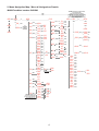
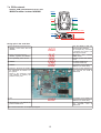
7.a PCBs network
Address PCB network/map electronic pcb
Assign pcb in the serial bus
2) Press and keep pressed the key
<more>, at the same time as
<menu>
A001
Now the display is ON and
shows the dmx address
(for example 001), the fixture
is supplied, the reset is not
done by the motors.
2) Press, and keep pressed,
<more>, together with <menu>
ALIG
Alignment and service
hidden menu .
3) <+> repeatedly until it shows
AMS
Modular system AMS hidden
menu.
4) <enter>
SAB2
To assign serial bus 2
(2 motors serial bus)
5) <enter>
01B2
The display shows 01B2 (pcb
address 1, 2 motors bus)
6) Press the key B of the PCB to
be addressed as number 1 in
the system.
Refer to the electronic PCB
map address to identify the
position of the pcbs.
The led A stops flashing for
few seconds, the PCB is
addressed.
7) <+>
02B2
The display shows 02B2 (pcb
address 2, 2 motors bus)
8) Repeat step n. 6 to address the
pcb 2 of serial bus 2.
The led A stops flashing for
few seconds, the is
addressed.
The 2 motors serial bus is completely assigned.
IWASH Flex edition / versione: 24/06/2003
bus 4
bus 2
add.2
add.4
add.1
add.2
add.1
lock
yoke lock other side
boccaggio dall’altro lato
display
add.3
Fixture position
Posizione proiettore
12

Now proceed with the assignment of 4 motors pcb in the bus 4
9) <menu>
SAB2
Back to the assignment of
serial bus 2
10) <+>
SAB4
To assign serial bus 4
(4 motors pcb)
11) <enter>
01B4
The display shows 01B4
(pcb address 1, 4 motors
bus)
12)Press the key B of the pcb to
address as number 1 in the sys-
tem.
Refer to the electronic pcb
address map to identify the
position of the pcb .
The led A stops flashing for
few seconds, the PCB is
addressed.
13) <+>
02B4
The display shows 02B4
(pcb address 2, 4 motors
bus)
14) Repeat step 12 to address pcb
2 of serial bus 4
The led A stops flashing for
few seconds, the PCB
is addressed.
15) Repeat step 12 and 13 to
address pcb 3 and 4 of the seri-
al bus 4
03B4
04B4
The 4 motors serial bus is fully assigned.
16) Press and keep pressed
<more> at the same time as
<menu>
A001
The fixture now is back to
its standard mode, the dis-
play shows the address
DMX, for example A001
13

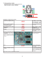
7.b Assegnazione schede
PCB network/mappa indirizzo schede elettroniche
Assegnare le schede nel bus seriale
1) Accendete il proiettore mante-
nendo il tasto <more> premuto.
A001
Il display si accende
mostrando l’indirizzo dmx
(ad esempio 001), il proiet-
tore è alimentato, i motori
non hanno eseguito il reset.
2) Premete e mantenere premuto
il tasto <more>, contempo-
raneamente a <menu>
ALIG
Menu nascosto allineamento
e di servizio
3) <+> ripetutamente fino a visual-
izzare AMS
AMS
Menu nascosto sistema
modulare AMS
4) <enter>
SAB2
Assegnare bus seriale 2 (per
le schede a 2 motori)
5) <enter>
01B2
Il display visualizza 01B2
(per scheda ad indirizzo 1,
bus 2 motori)
6) Premete il tasto B della scheda
da indirizzare come numero 1
nel sistema.
Riferitevi alla mappa indirizzo
schede elettroniche per individ-
uare la posizione fisica delle
schede.
Il led A smette di lampeggia-
re per pochi secondi, la
scheda è indirizzata.
7) <+>
02B2
Il display visualizza 02B2
(per scheda ad indirizzo 2,
bus 2 motori)
8) Ripetete l’operazione 6 per ind-
irizzare la scheda 2 del bus
seriale 2.
Il led A smette di lampeggia-
re per pochi secondi, la
scheda è indirizzata Il led A
smette di lampeggiare per
pochi secondi, la scheda è
indirizzata
Il bus seriale a 2 motori è completamente assegnato.
IWASH Flex edition / versione: 24/06/2003
bus 4
bus 2
add.2
add.4
add.1
add.2
add.1
lock
yoke lock other side
boccaggio dall’altro lato
display
add.3
Fixture position
Posizione proiettore
14

Procedete ora nell’assegnazione delle schede a 4 motori nel bus 4.
9) <menu>
SAB2
Ritorna all’assegnazione
bus seriale 2.
10) <+>
SAB4
Assegnare bus seriale 4
(per le schede a 4 motori)
11) <enter>
01B4
Il display visualizza 01B4
(per scheda ad indirizzo 1,
bus 4 motori)
12) Premete il tasto B della scheda
da indirizzare come numero 1
nel sistema.
Riferitevi alla mappa indirizzo
schede elettroniche per individ-
uare la posizione fisica delle
schede.
Il led A smette di lampeg-
giare per pochi secondi, la
scheda è indirizzata
13) <+>
02B4
Il display visualizza 02B4
(per scheda ad indirizzo 2,
bus 4 motori)
14) Ripetere l’operazione 12 per
indirizzare la scheda 2 del bus
seriale 4.
Il led A smette di lampeg-
giare per pochi secondi, la
scheda è indirizzata
15) Ripetere le operazioni 12 e 13
per indirizzare le schede 3 e 4
del bus seriale 4.
03B4
04B4
Il bus seriale a 4 motori è completamente assegnato
16) Premete e mantenere premuto
<more> contemporaneamente
a <menu>
A001
Il proiettore torna al suo
normale funzionamento, il
display mostra l’indirizzo
DMX, ad esempio A001
15

8.a Updating electronic pcb software
8.1. Updating DMX software
The software fit in the main microprocessor has been transferred to the dmx pcb.
8.2. 2-motors PCB software updating
The software contained in the main microprocessor has been transferred to the 2 motors pcb (pan and tilt).
8.3 Aggiornamento software schede 4 motori
The software contained in the main microprocessor has been transferred to the 4 motors pcb (all but for pan and tilt).
1) Switch on the fixture keeping the key
<more> pressed.
A001
Now the display is ON and shows the dmx address
(for example 001), the fixture is supplied, the reset
is not done by the motors.
2) Press, and keep pressed, <more> together
with <menu>
ALIG
Alignment and service hidden menu.
3) <+> repeatedly until it shows AMS
AMS
Modular system AMS menu
4) <enter>
SAB2
5) <+> repeatedly
UMT4
The display shows UMT4 (Updating 4 motors-
effect pcb, all excepted pan and tilt)
6) <enter>
SURE
The display shows SURE, waiting for confirmation
7) enter> to confirm
9999/0000
The display shows UMT4
(Updating 4 motors-effect pcb, all excepted pan
and tilt)
1) Switch on the fixture keeping the key
<more> pressed.
A001
Now the display is ON and shows the dmx address
(for example 001), the fixture is supplied, the reset
is not done by the motors.
2) Press, and keep pressed, <more> together
with <menu>
ALIG
Alignment and service hidden menu.
3) <+> repeatedly until it shows AMS
AMS
Modular system AMS menu
4) <enter>
SAB2
5- <+> repeatedly
UMT2
The display shows UMT2
(Updating 2 motors - pan/tilt pcb)
6) <enter>
SURE
The display shows SURE, waiting for confirmation
7) <enter> to confirm
9999/0000
The fixture starts the countdown download from
fixture memory to the 4 motors pcb (for the parts
referred).
1) Switch on the fixture keeping the key
<more> pressed.
A001
Now the display is ON and shows the dmx address
(for example 001), the fixture is supplied, the reset
is not done by the motors.
2) Press e and keep pressed <more>, together
with <menu>
ALIG
Alignment and service hidden menu.
3) <+> repeatedly until it shows AMS
AMS
Modular system AMS menu
4) <enter>
SAB2
5) <+> repeatedly
UDMX
The display shows UDMX
(Updating DMX pcb)
6) <enter>
SURE
The display shows SURE, waiting for confirmation
7) <enter> to confirm
9999/0000
The fixture starts the countdown download from
fixture memory to dmx pcb (for the parts referred)
16

8.b Aggiornamento software schede elettroniche
8.1 Aggiornamento software DMX
Il software contenuto nel microprocessore principale è stato trasferito alla scheda di ricezione dmx.
8.2 Aggiornamento software schede 2 motori
Il software contenuto nel microprocessore principale è stato trasferito alle schede contorllo 2 motori (pan e tilt).
8.3 Aggiornamento software schede 4 motori
Il software contenuto nel microprocessore principale è stato trasferito alle schede contorllo 4 motori (tutte ad eccezione di pan e tilt).
1) Accendete il proiettore mantenendo il tasto
<more> premuto.
A001
l display si accende mostrando l’indirizzo dmx (ad
esempio 001), il proiettore è alimentato, i motori
non hanno eseguito il reset.
2) Premete e mantenere premuto il tasto
<more>, contemporaneamente a <menu>
ALIG
Menu nascosto allineamento e di servizio.
3) <+> ripetutamente fino a visualizzare AMS
AMS
Menu sistema modulare AMS
4) <enter>
SAB2
5) <+> ripetutamente
UMT4
Il display visualizza UMT4
(Aggiornamento schede a 4 motori - effetti, tutte ad
eccezione di pan e tilt)
6) <enter>
SURE
Il display visualizza SURE, spettando conferma
7) <enter> per conferma
9999/0000
Il proiettore inizia il conto alla rovescia di download
dalla memoria del proiettore alle schede a 4 motori
(per la porzione che le riguarda)..
1) Accendete il proiettore mantenendo il tasto
<more> premuto.
A001
l display si accende mostrando l’indirizzo dmx (ad
esempio 001), il proiettore è alimentato, i motori
non hanno eseguito il reset.
2) Premete e mantenere premuto il tasto
<more>, contemporaneamente a <menu>
ALIG
Menu nascosto allineamento e di servizio.
3) <+> ripetutamente fino a visualizzare AMS
AMS
Menu sistema modulare AMS
4) <enter>
SAB2
5) <+> ripetutamente
UMT2
Il display visualizza UMT2
(Aggiornamento schede a 2 motori - pan/tilt)
6) <enter>
SURE
Il display visualizza SURE, aspettando conferma
7) <enter> per conferma
9999/0000
Il proiettore inizia il conto alla rovescia di download
dalla memoria del proiettore alle schede a 2 motori
(per la porzione che le riguarda).
1) Accendete il proiettore mantenendo il tasto
<more> premuto.
A001
l display si accende mostrando l’indirizzo dmx (ad
esempio 001), il proiettore è alimentato, i motori
non hanno eseguito il reset.
2) Premete e mantenere premuto il tasto
<more>, contemporaneamente a <menu>
ALIG
Menu nascosto allineamento e di servizio.
3) <+> ripetutamente fino a visualizzare AMS
AMS
Menu sistema modulare AMS
4) <enter>
SAB2
5) <+> ripetutamente
UDMX
Il display visualizza UDMX
(Aggiornamento scheda DMX)
6) <enter>
SURE
Il display visualizza SURE, aspettando conferma
7) <enter> per conferma
9999/0000
Il proiettore inizia il conto alla rovescia di download
dalla memoria del proiettore alla scheda dmx (per
la porzione che la riguarda).
17

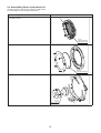
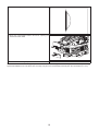
9.a. Assembling Super narrow beam kit
Coemar Kit code is : KIT89 KiIT ANTIALO LENS Ø=200.
For assemblling read the following instructions :
1) Open the upper cover
2) Untighten the screw A and remove the fresnel lens indica-
ted in the picture
LE 1295
FRESNEL LENS Ø200
LENTE FRESNEL Ø200
A
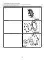
3) Remove athermic front glass (code VT194)
VT 194
GLAS Ø205
VETRO Ø205 TEMPERATO
4) Remove the reflector (code LEJ1970/2L)
LEJ 1970 / 2L
LENS Ø73
LENTE PARAB. Ø73
18

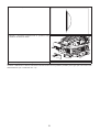
Remember that channel number 5 (speed) must be set at 0 value while using the iWash Flex Super narrow beam option. Using a
speed value different from 0 the fixture lose the step every time it is electronically removed (with dmx channels from 1 to 4).
5) Assemble the super narrow beam lens
6) Mount the counterweights behind the fixture replacing the
screws 4X14 with 4X30
7) Close the fixture as originally
19

9.b. Montaggio kit Super narrow beam
Il codice Coemar del kit a disposizione è il seguente : KIT89 - KIT LENTE ANTIALO Ø=200.
Per il montaggio del kit seguite le seguenti istruzioni :
1) Aprite il carter superiore
2) Svitate la vite A e rimuovete la lente Fresnel indicata in
figura
LE 1295
FRESNEL LENS Ø200
LENTE FRESNEL Ø200
A
3) Rimuovete il vetro temperato frontale (code VT194) e l’a-
nello di tenuta.
VT 194
GLAS Ø205
VETRO Ø205 TEMPERATO
4)Rimuovete la lente parabolica (code LEJ1970/2L)
LEJ 1970 / 2L
LENS Ø73
LENTE PARAB. Ø73
20
La pagina sta caricando ...
La pagina sta caricando ...
-
 1
1
-
 2
2
-
 3
3
-
 4
4
-
 5
5
-
 6
6
-
 7
7
-
 8
8
-
 9
9
-
 10
10
-
 11
11
-
 12
12
-
 13
13
-
 14
14
-
 15
15
-
 16
16
-
 17
17
-
 18
18
-
 19
19
-
 20
20
-
 21
21
-
 22
22


in altre lingue
- English: Coemar iWash Flex User manual
Documenti correlati
Altri documenti
-
Philips CRP614/01 Product Datasheet
-
 DTS XR 8 Wash Manuale utente
-
 Teclumen Spot 575 TM3 Manuale utente
-
 DTS XR8 SPOT Manuale utente
-
 DTS EVO Manuale utente
-
Diamond AL2381 Manuale utente
-
 DTS EUPHONY 3 Manuale utente
-
 DTS 03.MS014.EBLFP Manuale utente
-
 DTS XM 2500 Sport Manuale utente
-
 DTS XM 1200 SPOT Manuale utente


