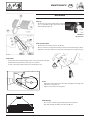
Operator's manual
+ INSTRUCTIONS FOR PRODUCT DELIVERY . . . Page 3
Ihre / Your / Votre • Masch.Nr. • Fgst.Ident.Nr.
GB Nr. 99 546.GB.80A.0
SILOPROFI 2 Profimatic
(Type 546)
SILOPROFI 3 Profimatic
(Type 547)

ALLG./BA SEITE 2 / 9300-GB
Important information concerning Product Liability.
According to the laws governing product liability, the manufacturer and dealer are
obliged to hand the operating manual to the customer at the time of sale, and to
instruct them in the recommended operating, safety, and maintenance regulations.
Confirmation is necessary to prove that the machine and operating
manual have been handed over accordingly.
For this purpose, document A is to be signed and sent to Pöttinger,
document B remains with the dealer supplying the machine, and the
customer receives document C.
In accordance with the laws of product liability, every farmer is an entrepreneur.
According to the laws of product liability, property damage is damage caused by a
machine and not to it. An excess of Euro 500 is provided for such a liabilioty.
In accordance with the laws of product liability, entrepreneurial property damages
are excluded from the liability.
Attention! Should the customer resell the machine at a later date, the operating
manual must be given to the new owner who must then be instructed in the
recommended regulations referred to herein.
GB
Dear Farmer
You have just made an excellent choice. Naturally we
are very happy and wish to congratulate you for
having chosen Pöttinger. As your agricultural partner,
we offer you quality and efficiency combined with
reliable servicing.
In order to assess the spare-parts demand for our
agricultural machines and to take these demands
into consideration when developing new machines,
we would ask you to provide us with some details.
Furthermore, we will also be able to inform you of new
developments.

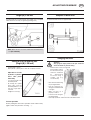
Dokument D
GB-0600 Dokum D Anhänger
PÖTTINGER Landtechnik GmbH
Industriegelände 1
A-4710 Grieskirchen
Tel. 07248 / 600 -0
Telefax 07248 / 600-2511
Machine checked according to delivery note. All attached
parts removed. All safety equipment, drive shaft and
operating devices at hand.
Operation and maintenance of machine and/or implement
according to operating instructions explained to the
customer.
Tyres checked re. correct pressure.
Wheel nuts checked re. tightness.
Drive shaft cut to correct lenght.
Correct power-take-off speed indicated.
Mechanical functions (opening of rear gate, pivoting
of cutting mechanism out/in, etc.) demonstrated and
explained.
Removing and mounting of knives explained.
Electrical connection to tractor established and checked
re. correct supply (54 g connected). Note references in
operating manual.
Fitting to tractor carried out: hight of drawbar adjusted,
brake cable installed, hand brake lever assembled in tractor
cabin.
Please check. X
According to the product liability please check the above mentioned items.
INSTRUCTIONS FOR
PRODUCT DELIVERY
GB
Function of electrical installation checked and explained.
Hydraulic connection to tractor established and checked
re. correct supply.
Hydraulic functions (drawbar, opening of rear gate, etc.)
demonstrated and explained.
Handbrake and operating brake tested re. function.
Trial run carried out and no defects found.
Functions explained during trial run.
Automatic on/off switch of loading mechanism checked.
Pivoting in transporting and operating position explained.
Information given re. optional extras.
Absolute need to read the operating manual indicated.
In order to prove that the machine and the operating manual have been properly delivered, a conrmation is necessary.
For this purpose please do the following:
- sign the document A and send it to the company Pöttinger or via the internet to www.poettinger.at
- document B stays with the specialist factory delivering the machine.
- document C stays with the customer.

GB
TABLE OF CONTENTS
- 4 -
9800-GB INHALT (546)
Table of contents
Meaning of warning signs .................................................................................. 5
Recommendations for work safety ..................................................................... 5
General safety tips for using the trailer .............................................................. 6
Travelling on roads ............................................................................................ 6
PUTTING INTO OPERATION ............................................................................ 6
Before starting work ........................................................................................... 6
Checking before operation ................................................................................. 6
Hydraulic connection .......................................................................................... 7
Connecting hydraulic lines ................................................................................. 7
Power supply ..................................................................................................... 8
To make the connection to the tractor ................................................................ 8
Installation of control panel ................................................................................ 8
Adjustment of drawbar to tractor’s towing coupler ............................................. 9
Raising the jack stand by hand .......................................................................... 9
Important hint! .................................................................................................... 9
Setting of Pick-up pivoting area (Height (M) = 460 mm) ................................. 10
Adaption to drive shaft ..................................................................................... 10
Garaging the trailer .......................................................................................... 10
Electro-Hydraulics ............................................................................................ 11
Control panel "D" ............................................................................................. 11
Control panel "L" .............................................................................................. 11
Explanation of control panel function ............................................................... 12
Swivelling of cutter bar ..................................................................................... 14
Cut with 35 blades ........................................................................................... 14
Cut with 10 blades ........................................................................................... 14
Advice in case of press channel blockage ....................................................... 15
Automatic loading ............................................................................................ 16
Disruptions and remedies to power failure ....................................................... 17
Scraper floor drive - Adjustment possibilities ................................................... 18
Removal of regulating rollers ........................................................................... 19
Scraper floor switch ......................................................................................... 19
Installing an oil pressure switch ....................................................................... 19
Starting the loading process ............................................................................ 20
To observe during the loading process! ........................................................... 20
Tailgate and cross conveyor belt ...................................................................... 21
Operating without cross conveyor belt ............................................................. 21
Cross conveyor belt ......................................................................................... 22
Correct belt tension .......................................................................................... 22
Replacing belt .................................................................................................. 22
Adjusting belt tension ....................................................................................... 22
Tailgate ............................................................................................................. 23
Unloading the trailer ......................................................................................... 24
Shut-off clutch (NS) .......................................................................................... 24
Road travel ....................................................................................................... 24
Unloading the trailer ......................................................................................... 25
Unloading with regulating rollers ...................................................................... 25
Unloading without regulating rollers ................................................................. 25
Unloading with cross conveyor ........................................................................ 25
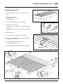
Assembling the top frame section .................................................................... 26
Advice for general maintenance ...................................................................... 28
Opening the side protectors ............................................................................. 28
Cleaning of machine parts ............................................................................... 28
Brake adjustment ............................................................................................. 28
Hydraulic unit ................................................................................................... 29
Gas container ................................................................................................... 29
Maintenance .................................................................................................... 30
Cutting unit ....................................................................................................... 31
Adjusting measurement for end switch ............................................................ 32
Safeguarding the electrical unit ........................................................................ 32
Automatic Chain Lubrication 1) ........................................................................ 33
Transmission .................................................................................................... 33
Technical data SILOPROFI 2 ......................................................................... 39
Optional equipment .......................................................................................... 39
Technical data SILOPROFI 3 ......................................................................... 40
Optional equipment .......................................................................................... 40
Defined use of the trailer .................................................................................. 41
Correct loading: ................................................................................................ 41
Supplement ...................................................................................................... 44
DRIVESHAFT .................................................................................................. 46
Auflaufbremsanlage ......................................................................................... 47
Abstellen des Anhängers ................................................................................. 47
Fehlerursachen und deren Beseitigung ........................................................... 48
Auflauf-Achse mit Rückfahrautomatik .............................................................. 49
Einstellen der Nockenbremse Typ: 30-4010 (300x60) ..................................... 49

- 5 -
AZB 9700-GB (544)
GB
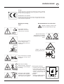
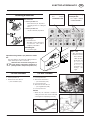
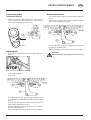
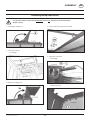
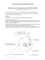
WARNING SIGNS
CE sign
The CE sign, which is affixed by the manufacturer, indicates outwardly
that this machine conforms to the engineering guideline regulations and
the other relevant EU guidelines.
EU Declaration of Conformity
By signing the EU Declaration of Conformity, the manufacturer declares
that the machine being brought into service complies with all relevant
safety and health requirements.
495.151
Meaning of warning
signs
Turn engine off when
adjustment, service and
repair work is to be done.
Never reach into the pick-up
area as long as tractor
engine is running with PTO
connected.
Never reach into the crushing
danger area as long as parts
may move.
Don't step on loading
platform if PTO is connected
to the tractor and the Engine
is running.
Stay clear of gate swinging
area while tractor engine is
running. Access only allowed
when safety lock is applied.
Recommendations for work safety
All points referring to satety in this
manual are indicated by this sign.
Wait until all machine
components have stopped
completely before touching
them.
Danger - stay clear of
rotating machine parts.
495.679
Warning against damage
•the bolts on the left and right
hand trailer sides must
always be equally positioned
otherwise the tailgate and
swivel sections will be
damaged;
therefore
- always check before opening
the tailgate hydraulically

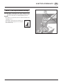
Before starting work
a. Before commencing work, the operator must be aware of
all operating devices and functions. The learning of these
is too late after having already commenced operation!
b. The vehicle is to be tested for traffic and operating safety
before each operation.
c. The danger of being crushed or cut exists in the Pick-up,
cutting unit, tailgate and upper extension areas. All persons
must be shown out of these areas before activating hydraulic
equipment and turning on the drive.
d. Before driving the vehicle, the driver must ensure that
nobody will be endangered and that no obstructions are
present. If the driver is unable to see and have an overall
view of the roadway directly behind the trailer, he must be
guided by somebody while reversing.
e. Observe the safety tips which are attached to the trailer. An
explanation of what the individual graphic warning symbols
mean can be found on page 4.
f. Observe also the tips in the respective chapters and in the
supplement to this operating manual.
Checking before operation
The following tips should make the trailer's operation
easier for you. Detailled information for individual
points can be found in the respective chapters in this
operating manual.
1. Check that all safety equipment (coverings, casings, etc.)
are in proper order and fitted in position on the trailer.
2. Grease the trailer in accordance with the lubrication chart.
Check the gearing for tightness and the oil level.
3. Check that tyres have the correct air pressure.
4. Check that wheel nuts are sitting firmly.
5. Ensure the correct p.t.o.-r.p.m..
6. Make the electrical connections to the tractor and check
that they are correct. Take note of the tips in the operating
manual!
7. Carry out the following adaptions:
•Drawbar height
•Laying of brake cable
•Install hand brake lever in the tractor cabin.
8. Secure trailer using only the fixtures provided.
9. Cut drive shaft to the correct length and check the function
of the overload safety (see supplement).
10. Check the electronic unit function.
11. Connect hydraulic lines to tractor.
•Check hydraulic hoses for damage and wear.
•Ensure the correct connection.
12. All swivelling parts (tailgate, adjusting lever, etc.) must be
secured against dangerous position changes.
13. Check parking brake and service brake functions.
General safety tips for using the
trailer
Tips for travelling with the trailer
The handling of the tractor is influenced by the trailer
coupled to it.
•Danger of tipping exists when working on slopes.
•The driving must be adapted
to the corresponding terrain
and ground conditions.
•The towing vehicle is to be
sufficiently equiped with
weights at the front or at the
rear in order to guarantee the
steering and braking capacity
(a minimum of 20% of the
vehicle's tare weight on the
front axle).
•The transport of persons on the machine is not permitted.
Tips for coupling and uncoupling the trailer
•Danger of injury exists when coupling the implement to the
tractor!
•As long as the tractor is moving backwards, do not step
between it and the trailer when coupling.
•Nobody is to stand between the tractor and trailer without
the vehicles being secured against
rolling with the parking brake and/or
wheel chocks.
•Drive shaft connection or
disconnection is only to be undertaken
when the motor has stopped.
Parking the implement
•When the implement ist parked, either
remove the driveshaft and store it, or
secure it with a chain.
Do not use retaining chain (H) for this.
Only use the trailer according to regulations!
Regulations for Use: See chapter "Technical Data".
•The trailer's load limits (permitted axle load, support load,
total weight) may not be exceeded. The relevant details
are located on the right side of the trailer.
•In addition, observe the power limits of the tractor being
used.
Travelling on roads
•Observe the road rules.
•The tailgate must be closed when travelling on public
roads. Lighting devices must be fitted vertically to the road.
20%
Kg
GB
- 6 -
9500 GB INBETRIEBNAHME (511)
PUTTING INTO OPERATION

ERSTANBAU 9800-GB (544)
FIRST-TIME CONNECTION TO TRACTOR
GB
- 7 -
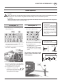
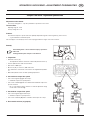
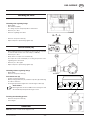
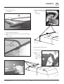
ST
Take care with tractors with a closed hydraulic system
John-Deere, CASE - MAXXUM, CASE - MAGNUM,
FORD SERIE 40 SLE
Before coupling, the screw (7) on the hydraulic block is to be screwed completely in.
Standard position with an open hydraulic system
The position of the screw (7) is set in the factory.
The screw (7) must be screwed out to the point where the screw head is level with the surface of the
hydraulic block.
Warning!
If this is not done then the overload valve on the tractor’s hydraulics is continually in use and excessive
warming of the oil will occur!
LS = Load sensing
Connecting hydraulic lines
- Turn p.t.o. off before connecting
- Put lever (ST) on the control unit into the
floating position (neutral position).
- Take care that snap-lock couplers are clean.
Hydraulic connection
Single-action control unit
Should the tractor only have a
single-action servo-valve, then it is
absolutely necessary to have an
oil-return pipe (T) fitted by a
specialist.
- Connect pressure hose (1) to the
single-action control unit. Couple the
oil-return hose (2) (with the greater
diameter) to the tractor’s oil-return
system.
Double-action control unit
- Connect pressure line (1) and oil-
return pipe (2) (pipe with the greater
diameter is the oil-return pipe).
Note
If oil should become warm during
operation then a single-action
control unit should be connected
(see above).
Baujahr: - 1997 Baujahr: + 1998
Take care with
tractors with a
closed hydraulic
system
Standard position
with an open
hydraulic system
Take care with
tractors with a
closed hydraulic
system
Standard position
with an open
hydraulic system

ERSTANBAU 9800-GB (544)
FIRST-TIME CONNECTION TO TRACTOR
GB
- 8 -
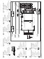
12V=
11 9
3-POL
"15/30"
"31"
10
TD 52/97/12
86 86a 87
85 30
+
Power supply
Tractor equipment
- Fix accompanying 3-pole power socket to the rear of the tractor
- Power supply with relais (9)
- Control relais with ignition switch (10)
- Conductor diameter 4 mm
2
- Fuse 16A (11)
Elektric plan see spare parts book
• This conversion is to be made only by a specialist
• Do not connect directly to ignition switch (danger of fire or damage to electrical unit).
• Use only recommended-strength fuses as the use of stronger fuses will destroy the electrical unit!
To make the connection to the tractor
- After completion of the work as shown, plug the 4-pole and 7-pole plugs into the tractor's
power sockets.
- Check that trailer lights are functioning.
Installation of control panel
- Install the accompanying splicing plate (13) into tractor cabin so that it is within the driver’s
sight and reach.
- Place the control panel (14) in the splicing plate.

ERSTANBAU 9800-GB (544)
FIRST-TIME CONNECTION TO TRACTOR
GB
- 9 -
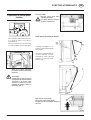
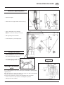
Important hint!
Driveshaft overload safety (540 r.p.m. , 1000 r.p.m.) see page 12.
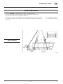
Adjustment of drawbar to tractor’s towing coupler
- Extend the drawbar coupling (A) so that there is sufficient gap between drive shaft and
drawbar of attached trailer, especially in the event of pivoting.
Raising the jack stand by hand
- Couple the trailer to tractor
- Take load off jackstand by using pivoting drawbar
( see chapter “Explanation of control panel
function”).
- Pull out locking bolt (1 ), swing jack stand up and
lock again.
- Make sure bolt is properly locked in (1).

9700-GB DEICHSELEINSTELLUNG (544)
GB
- 10 -
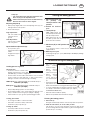
ADJUSTING DRAWBAR
Height (M) = 460 mm
To allow pick-up to work properly, the height (H ) of coupled
trailer must be correctly set (pick-up pivoting area).
Note: Where the floor is uneven, reduce the measurement by
1 cm (M = 450 mm)
Setting of Pick-up pivoting area
(Height (M) = 460 mm)
- Couple trailer to tractor
- Both hydraulic cylinder pistons must be completely inserted.
Adjustment of both
hydraulic cylinders
must take place
alternately
- Loosen lock nut (K) on the
threaded spindle
- By twisting the cylinder
piston (50), screw the
threaded spindle in or out
until the height (M) is
achieved.
- Retighten lock nut (K)
Put into operation
Before putting the tractor into operation check vehicle safety
(lights, brake unit, protective covering, .....).
Adaption to drive shaft
To shorten the drive shaft see supplement-B
Garaging the trailer
Attention!
Only garage an empty trailer on the jack stand and
chock the wheels to prevent rolling.
•Park the trailer on firm, level ground.
If the ground is soft then
the area where the jack
stand is to stand must
be appropriately
increased using a
suitable aid (e.g.
wooden board).
- Raise the trailer a little using
the pivoting drawbar .
- Pull out locking bolt (1),
swing jack stand down and
lock again.
- Make sure bolt (1) is
properly locked in!
- Lower the trailer using the
pivoting drawbar.
- HUncouple hydraulic- and electric lines and detach trailer.

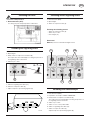
ELEKTROHYDRAULIK 9900-GB (546)
ELECTRO-HYDRAULICS
GB
- 11 -
Control panel "D"
This control panel is a standard fitting in trailers
with regulating rollers.
•To load trailer, it is necessary to plug in control
panel (14b). This mode of operation (ON) enables
every switch function to be used.
•To unload trailer, control panel "D" can be plugged
into socket on tail gate (14a).
This mode of operation does not enable switch
functions for the pick-up lift, pivoting drawbar and
for swivelling the cutter bar to be used.
•We recommend the use of control panel
"L" in addition to control panel "D".
Control panel "L" then remains in the
tractor cabin during operation and
control panel "D" on the tail gate.
Control panel "L"
This control panel is a standard fitting in
trailers without regulating rollers.
•Depending on trailer equipment, the order
of the operating controls can differ slightly
from the diagramm shown.
- Both "QB" switches are only available
on trailers with a cross belt.
- The "AUTO" switch are only available
on trailers with a automatic loading
system.
.
The following operating manual
applies to trailers fitted with all addi-
tional equipment.
Electro-Hydraulics
Safety tips
Please take particular care when the operating elements on the trailer and the tractor are to be used simultaneously by more
than one person. A conscientious arrangement should be made by those concerned before operation.
An example:
Danger of injury arises if a person stands at the rear of the trailer and somebody in the tractor cabin activates a switching function
(opening the tailgate, switch on the driving gear, ...).
- To unload the trailer push the
switch back (A).
The switch is engaged and the
scraper floor runs backward (KR).
- To load the trailer, without using
the automatic load for example,
push the switch forward (B).
The scraper floor runs backward
(KR) as long as the switch is kept
in this position.
- Push switch down (B).
The scraper floor runs forward (KV).
KB KV-KR
KV KR

ELEKTROHYDRAULIK 9900-GB (546)
ELECTRO-HYDRAULICS
GB
- 12 -
ST
Explanation of control panel
function
- Move lever (ST) to “ON” position and secure.
In so doing the trailer’s control block is
supplied with oil.
- By using a switch on the control panel (14)
the relative hydraulic function takes place.
With all of these switching
procedures, be alert to the danger
distances!
An example:
Danger of injury arises if a person
stands at the rear of the trailer and
somebody in the tractor cabin
activates a switching function
(opening the tailgate, switch on
the driving gear, ...).
For your safety!
Bolt the switch lever when
unloading the trailer..
In so doing, the press and pick-
up drive is switched off.
Safety device for closing of tailgate:
Lowering the tailgate to "C"
position is effected through its
own weight.
Only after reaching position "C"
is the hydraulic function
activated by switch (56) and
tailgate is lowered under
pressure (G).
Keep clear of swivel range!
Do not stay under raised tailgate
Tailgate must be closed when driving on
the road.

ELEKTROHYDRAULIK 9900-GB (546)
ELECTRO-HYDRAULICS
GB
- 13 -
Pivoting drawbar
- Push switch up (A) and
drawbar is lowered.
- Push switch down (B) and
drawbar pivots up.
When driving on the
road the drawbar
cylinder must be
completely
inserted.
Raising and lowering pick-up
- Push switch down (B), pick-
up is lowered and remains
in floating position.
- Push switch up (A), pick-up
is raised.
Unlocking the press
drive switch lever
automatically
switches on the
press and pick-up
drive (refers only to
trailers with
reguating fittings).
Loading without auto-
matic-loader
- To load the trailer, without
using the automatic load for
example, push the switch
back (A).
The scraper floor runs
backward (KR) as long as
the switch is kept in this
position.
FULL
If the load presses
against the tailgate
resp. on the lower
regulating roller, the
scraper floor drive is
turned off by means
of an switch and the
lamp (FULL) on the
control panel lights.
The lamp goes out
only when the pick-
up is raised.
The scraper floor
drive can be
activated again
- when the tailgate is
opened
- when the dispensing
rollers are switched
on
Trailer with regulating fittings
- To unload the trailer push the
switch back (A).
The switch is engaged and the
scraper floor runs backward
(KR).
- Push the switch forward (B).
The scraper floor runs forward
(KV).
The load pressure on the
regulating rollers is decreased.
- The scraper floor speed is
adjusted using the power
regulator.
Dispensing rollers
- When switch is
pushed up (A), then
dispensing rollers
are switched on.
- When switch is
pushed down (B),
then dispensing
rollers are switched
off.
Dry forage top frame
- Lever to position "D"
- When switch is pushed
up (A), then top frame
folds up.
- When switch is pushed down (B),
then top frame folds down.
Tailgate
- Lever to position "R"
- Push switch up (A).
Tailgate swings up to "D" position.
The lamp above the switch remains
alight as long as the tailgate is open.
- Push switch down (B).
Tailgate is lowered and closed.
The lamp above the switch goes out
when the tailgate is completely closed.
Safety device for closing of
tailgate:
- see previous page
STOP - pressure switch
This switch acts as an
EMERGENCY SHUT-OFF
switch.
When this switch is activated,
the regulating rollers drive
and scraper floor drive are
switched off.
The control light intergrated
into the switch lights up, and
the regulating rollers drive
can only be switched on again
when the STOP - pressure
switch is depressed once
again and the control light
goes out.
Note! The scraper floor
push-button switch
function is only
interrupted.
If the switch is in the A
position, then after the
STOP - pressure switch
shut-off function has
been cancelled the
scraper floor switches
itself on again.
KB KV-KR
KR
KV
R
D

ELEKTROHYDRAULIK 9900-GB (546)
ELECTRO-HYDRAULICS
GB
- 14 -
Swivelling in
- Push switch left.
The lamp over the switch goes
out when the cutter bar is
completely swivelled in.
Swivelling out
- Push switch rigth.
Unloading using
conveyor belt
See chapter "
CROSS
CONVEYOR BELT
".
Automatic load
See chapter
"Automatic Load".
Operation using buttons (57) above the cutter
bar
Use these buttons only when the loading channel is
empty and the press drive is turned off!
Attention! Take care that the cutting unit is in
proper working order before swivelling it in
(damaged cutters, warped components, etc).
OFF - ON
•After switching off
the tractor´s motor
- Move switch to
"OFF" position.
Doing this will
prevent
unintentional
battery
discharge e.g.
during the
night.
Swivelling of cutter bar
TD 83/97/4
10
25
TD 83/97/5
25
10
Preselection
•Lever in position "A"
- both cutter bars (25, 10) swivel
- operating position for loading the
trailer
•Lever in position "B"
- only the cutter bar (25) swivels
57L
A
B
TD 83-97-7
R
D
57R
Cut with 35 blades
1. Lever in position "A"
2. Swivwel both cutter bars in
•press left button (57L)
Cut with 10 blades
1. Lever in position "A"
2. Swivel both cutter bars in
•press left button (57L)
3. Lever in position "B"
4. Swivel the 25-cutter bar out
•press right button (57R)
5. Lever in position "A"
Variant
•When only one cutter bar is needed for
cutting, the lower cutter can be swivelled
out using the accompanying lever (H).

ELEKTROHYDRAULIK 9900-GB (546)
ELECTRO-HYDRAULICS
GB
- 15 -
Advice in case of press channel blockage
Warning! When a blockage in the press channel occurs,
DO NOT use the button (on the right) to swivel the cutter
bar out as this will occur under hydraulic pressure.
Remedy
- Move switch on control panel to position "A" and hold, simultaneously
engaging the p.t.o..
Running drive shaft swivels both cutter bars out.
- After clearing the blockage from the cutter bar,
swivel it back in (B).

9700-GB LADEAUTOMATIK (544)
AUTOMATIC - LOADING
GB
- 16 -
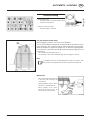
Automatic loading
•Push switch up (A)
- Automatic loader is activated and the switch
remains in the up position.
•Switch in centre position (0)
- Automatic loader is turned off.
How the automatic loader works
When loading the trailer the area at the front is filled first.
As soon as the load lifts the flap (58), the scraper floor drive is turned on by means
of the switch (59). The scraper floor will run until the flap (58) is lowered again.
When the load presses against the tailgate resp. on the lower regulating roller,
the scraper floor is turned off automatically and the lamp (FULL) lights up on the
control panel.
- Raise the pick-up, lamp (FULL) goes out.
The scraper floor drive can be activated again when the tailgate is opened.
Note
If an additional function is required during the scraper floor operation, then
the operation is interrupted automatically for the time period required.
Maintenance
- Disconnect the electrical connection
to the tractor when working on the
electrical unit.
- Change hydraulic oil in accordance
with tractor's operating manual.
- When welding on the trailer,
disconnect all connections to the
tractor and uncouple the trailer.

9700-GB ELEKT. STÖRUNGEN (544)
ELECTRO-HYDRAULICS
GB
- 17 -
Disruptions and remedies to power failure
1. Raising pick-up
•Push buttons (Y5 und Y6)
- pick-up is raised.
Lowering pick-up
•Push button (Y6)
- pick-up is lowered
2. Dispensing rollers
•Push buttons (Y4 und Y7) simultaneously
- Dispensing rollers drive is switched on.
Switching off the dispensing rollers drive:
- Push button (Y7).
3. Swiveling pivoting drawbar up
•Push buttons (Y5, Y8 und Y9) simultaneously
- drawbar pivots up.
Lowering pivoting drawbar
•Push buttons (Y4, Y8 und Y9) simultaneously
- drawbar is lowered.
4. Cross conveyor belt right running "ON"
- Push buttons on valves "Y5,Y10,Y11" simultaneously.
5. Cross conveyor belt left running "ON"
- Push buttons on valves "Y4,Y10,Y11" simultaneously.
Cross conveyor belt "OFF"
- Push buttons on valves "Y10 und Y11" simultaneously.
6. Swivelling cutting unit in
•Push buttons (Y4, Y12 und Y13) simultaneously
- cutting unit is swivelled in.
Swivelling cutting unit out
•Push buttons (Y5, Y12 und Y13) simultaneously
- cutting unit is swivelled out.
7. Opening tailgate
•Push buttons (Y5, Y14 und Y15) simultaneously
- tailgate swivels up to position"D".
Closing tailgate
•Push buttons (Y4, Y14 und Y15) simultaneously
- tailgate is closed.
8. Scraper floor forward run
•Push button (Y1)
- Scraper floor runs forward (KV).
9. Scraper floor
•Push button (Y2)
- Scraper floor runs (KR).
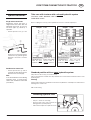
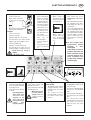
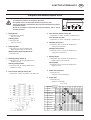
Y10 Y11
Querförderb.li
Querförderb.re
ein
ein
aus
aus
Pick-up
Knickdeichsel
Ladeautomatik
Kratzboden
Rückwand
Schneidwerk
MAGNETVENTILE Y2 Y4 Y5 Y6 Y8 Y15
Funktionsschaubild
heben
heben
ein
senken
senken
aus
auf
laden
ein
zu
entladen
aus
TD 51/97/45 (495.675)
Y9 Y12 Y13 Y14
FUNKTIONEN-PULT Y1
Vorlauf
Kratzboden
Dosierer
ein
aus
Y7
1
2
3
4
5
6
7
8
9
Function diagram
KB KV-KR
KV KR
•When there is a disruption in the electrical unit, the required hydraulic function can
be carried out by means of an emergency application.
The hydraulic block is located under the left front protective cover.
The function diagram´s analogue shows the respective outlet button to be used for
the required function.
Be alert to the dangers involved with all raising and lowering, and on and off
switching activities!

GB
SCRAPER FLOOR DRIVE - ADJUSTMENT POSSIBILITIES
- 18 -
9800-GB KR-EINSTELLUNG (546)
Scraper floor drive - Adjustment possibilities
Adjustment at the selector
The factory setting (0.6 - 1.7 A) offers problem-free operation in most cases.
Technical data:
Adjusting range: 0 - 2.4 A
Factory setting: 0.6 - 1.7A
Problem:
The desired scraper floor speed cannot be optimally adjusted through the current regulator (I) in the selector,
- e.g. the maximum or minimum speed.
This can happen occasionally by reason of the varying performance ranges of the various tractors.
ST
Remedy:
The following work is to be carried out only by specialists!
Take care!
Turning machine parts. Keep at a safe distance!
1. Preparation
•Dismantle selector (14)
- The adjustments must be carried out on the board (inside the selector).
•Connect hydraulic lines and electrical cables.
•Start tractor - 2000 r.p.m.
•Move lever (ST) on selector to „ON“ and secure.
This enables the control block on the trailer to be supplied with hydraulic
oil.
•Wait until hydraulic oil has reached operating temperature.
2. Set maximum scraper floor speed
•Turn current regulator (I) right until it stops.
= maximum scraper floor speed position.
•Turn screw on trimmer (II) with a screwdriver until maximum scraper floor
speed is reached.
- Do not turn trimmer further otherwise a reduced adjustment range
results at the control knob (I).
3. Set minimum scraper floor speed
•Turn current regulator (I) left until it stops.
= minimum scraper floor speed position.
•Turn screw on trimmer (III) with a screwdriver until scraper floor stops.
4. Re-assemble selector (14) properly.

- 19 -
(540) DOSIERER 9200 GB
GB
REGULATING ROLLERS
Removal of regulating rollers
- Open trailer tailgate.
- Relax chain tension (58) and take off drive chains (1).
- Remove metal plates (2) left and right.
Note! Do not alter the setting of screws (X).
- Slide regulating rollers backwards.
- Re-fit metal plates (2) left and right again.
Scraper floor switch
- When regulating rollers are removed the split pin
must be in Position 0, otherwise the scraper floor
drive will be permanently switched off.
- The split pin must be in Position D
for installed regulating rollers.
Installing an oil pressure
switch
It is recommended that an oil pressure switch (3) be installed when operating without
regulating rollers.
When the load presses against the tailgate, the scraper floor drive is automatically
switched off by means of the oil pressure switch.
The oil pressure switch has no function when regulating rollers are installed.
- Electro-connection see spare parts list, circuit diagram on plate 01.
- Setting on knob: 220 - 240 bar.
220 - 240 bar

9700-GB BELADEN (546)
LOADING THE TRAILER
- 20 -
GB
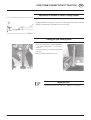
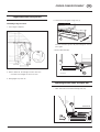
Starting the loading process
1. Move control lever (43)
for pick-up and
conveyor drive to "ON"
position.
2. Switch on tractor’s
p.t.o..
3. Lower pick-up.
Take care! Doing this
automatically switches on the
Pick-up and press drive.
When switch lever „43“ is in
the „OFF“ position then the Pick-up and
press will not be activated.
4. Move lever (ST) to “ON” position and
secure.
In so doing the trailer’s control block is
supplied with oil.
5. Observe p.t.o.-r.p.m.
•Load using average p.t.o.-r.p.m. (400-450 rpm / 780-850 rpm) and high
running speed.
To observe during the loading process!
•Only raise pick-up
when loading
channel is empty.
•When driving
through curves
reduce motor r.p.m.
•When driving
through sharp
curves switch off
p.t.o. and raise pick-
up.
•Avoid uneven loads!
Important because of possible drawbar overloading (see
details on the drawbar concerning permitted support load).
•To ensure optimal filling of load space switch on scraper
floor briefly or activate the automatic loader (see chapter
“ELECTRO HYDRAULICS”).
•Watch the trailer fill indicator (FULL).
•Observe the permitted axle load and total weight!
Finishing the loading process
1. Raise Pick-up.
Doing this automatically switches off the Pick-up and conveyor drive.
2. Move the switch lever „43“ to the „OFF“ position.
This position is for your safety. Doing this prevents the Pick-up and
press from being unintentionally activated, e.g. when lowering the Pick-
up while the p.t.o. is running.
Safety tips:
•Turn off the drive motor and take off the drive shaft
when carrying out all adjustment work.
•Faults in the Pick-up area are to be eliminated only
when the drive motor has been stopped.
Adjusting the pick-up
1. Raise pick-up slightly and secure with adjusting struts (51), left
and right sides in same position.
2. Secure with linch pin.
High adjustment:
with tall stubble and
extremely uneven
ground.
Low Adjustment:
with short green fodder
and even ground.
Impact deflector adjustment (52)
- In low position (T) for
small swaths and short
fodder.
- In high position (H) for
high swaths.
Loading process in general
Important tips:
•A transfer, which is located on the
drawbar, tells which p.t.o.-r.p.m. (450
rpm/1000 rpm) your trailer is equipped for.
•Therefore take care that a drive shaft with the correct overload
safety is used (see spare parts list), so that no unnecessary
damage is caused to the trailer through overloading.
1000 r.p.m.:Use a driveshaft with an overload safety of
1050 Nm (107 kpm).
540 r.p.m.:Use a driveshaft with an overload safety of
1500 Nm (153 kpm).
•Always adapt driving speed to the surroundings.
•Avoid making sudden curves when driving through hills and
valleys, and when transversing slopes (danger of tipping).
•Cut short with less r.p.m., greater speed and bigger swaths.
Loading green fodder
- As a rule green fodder is collected in swaths.
- Cut swaths collected are always stalk heads.
- Set deflector (52) low position (T).
Loading dry fodder
- Correct dry fodder collection is in swaths.
- Set deflector (52) in the position (H).
ST
540 Upm 1000 Upm
La pagina si sta caricando...
La pagina si sta caricando...
La pagina si sta caricando...
La pagina si sta caricando...
La pagina si sta caricando...
La pagina si sta caricando...
La pagina si sta caricando...
La pagina si sta caricando...
La pagina si sta caricando...
La pagina si sta caricando...
La pagina si sta caricando...
La pagina si sta caricando...
La pagina si sta caricando...
La pagina si sta caricando...
La pagina si sta caricando...
La pagina si sta caricando...
La pagina si sta caricando...
La pagina si sta caricando...
La pagina si sta caricando...
La pagina si sta caricando...
La pagina si sta caricando...
La pagina si sta caricando...
La pagina si sta caricando...
La pagina si sta caricando...
La pagina si sta caricando...
La pagina si sta caricando...
La pagina si sta caricando...
La pagina si sta caricando...
La pagina si sta caricando...
La pagina si sta caricando...
La pagina si sta caricando...
La pagina si sta caricando...
La pagina si sta caricando...
-
 1
1
-
 2
2
-
 3
3
-
 4
4
-
 5
5
-
 6
6
-
 7
7
-
 8
8
-
 9
9
-
 10
10
-
 11
11
-
 12
12
-
 13
13
-
 14
14
-
 15
15
-
 16
16
-
 17
17
-
 18
18
-
 19
19
-
 20
20
-
 21
21
-
 22
22
-
 23
23
-
 24
24
-
 25
25
-
 26
26
-
 27
27
-
 28
28
-
 29
29
-
 30
30
-
 31
31
-
 32
32
-
 33
33
-
 34
34
-
 35
35
-
 36
36
-
 37
37
-
 38
38
-
 39
39
-
 40
40
-
 41
41
-
 42
42
-
 43
43
-
 44
44
-
 45
45
-
 46
46
-
 47
47
-
 48
48
-
 49
49
-
 50
50
-
 51
51
-
 52
52
-
 53
53


Pottinger SILOPROFI 2 Istruzioni per l'uso
- Tipo
- Istruzioni per l'uso
- Questo manuale è adatto anche per
in altre lingue
Documenti correlati
-
Pottinger BOSS L 25 T Istruzioni per l'uso
-
-
-
-
-
-
-
-
-