
A
Overview
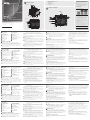
VM3200 Front View
1
LCD Display
2
Function Pushbuttons
3
Input Pushbuttons (1-32)
4
Output Pushbuttons (1-32)
5
Alarm LED
6
Redundant Power LED
7
Primary Power LED
8
Handles
9
Recessed Handles
10
Cable Strap
B
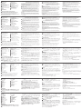
Hardware Installation
Installation of the VM3200 is simply a matter of connecting the
appropriate cables. Refer to the installation diagram above (the numbers
in the diagram correspond to the steps below), and do the following:
1
Use a grounding wire to ground the unit by connecting one end of
the wire to the grounding terminal, and the other end of the wire to a
suitable grounded object.
Note: Do not omit this step. Proper grounding helps to prevent
damage to the unit from surges or static electricity.
2
Unscrew the covers on the VM3200’s rear panel and insert the I/O
boards into the vertical slots (see VM3200 user manual, page 28, for
details).
3
Connect your A/V source device(s) to the Video and Audio port(s) of
the Input Board on the VM3200.
4
Connect your video display device(s) to the Video port(s) of the Output
Board on the VM3200.
5
Connect your speakers / audio output device(s) to the Audio port(s) of
the Output Board on the VM3200.
6
(Optional) If you are using the serial control function to control multiple
VM3200’s, use an appropriate serial cable to connect the computer or
serial controller to the VM3200’s female RS-485 / RS-422 captive screw
connector. The VM3200 package includes a terminal block connector
that can be used for this connection.
7
(Optional) If using the remote operation features (web GUI), plug a Cat
5e cable from the network into the VM3200’s Ethernet port.
8
(Optional) If you are using a serial control function, use an appropriate
serial cable to connect the computer or serial controller to the
VM3200’s female RS-232 serial port.
9
Plug the power cord supplied with the package into the VM3200’s
3-prong socket, and then into a power source.
10
(Optional) Plug in an additional power module for redundancy if
required.
Note: Secondary power modules are not included in the package. See
the VM3200 user manual, Optional Equipment, page 11, for
details.
11
Power on the VM3200 and all devices in the installation.
C
Operation
The VM3200 can be confi gured and operated locally via the front panel
display and pushbuttons; remotely over a standard TCP/IP connection via
graphical user interface (GUI) using a web browser; or by an RS-232 / RS-
485 / RS-422 serial controller. For more detailed information about control
operations, download the VM3200 user manual from our website: www.
aten.com
Front Panel Operation
The VM3200’s front panel display operation is intuitive and convenient.
Please note the following operation conventions:
• Use the Input/Output pushbuttons to confi gure port connections.
• Use the Video pushbutton to confi gure video connections.
B
Front View
Rear View
Hardware Installation
© Copyright 2019 ATEN
®
International Co., Ltd.
ATEN and the ATEN logo are trademarks of ATEN International Co., Ltd. All rights reserved. All
other trademarks are the property of their respective owners.
Part No. PAPE-1223-G40G Printing Date: 11/2019
32 x 32 Modular Matrix Switch
Quick Start Guide
VM3200
VM3200 32 x 32 Modular Matrix Switch
www.aten.com
Commutateur matriciel modulaire 32 x 32 VM3200
www.aten.com
Modularer 32x32-Matrix-Switch VM3200
www.aten.com
VM3200 32 x 32 Conmutador de matriz modular
www.aten.com
Switch matrix modulare VM3200 32 x 32
www.aten.com
ATEN VanCryst
™
• Use the Audio pushbutton to confi gure audio connections.
• Use the Profi le pushbutton to select a profi le or switch between the
connection profi les which have been added to the profi le selection list.
• Use the Menu pushbutton to access the Menu page options.
• Use the
←
pushbutton to go back a level, return to the Initial screen,
or exit.
• Use the
↑↓
pushbutton to go to the next or pevious options.
Note: To operate the device using the front panel display, the default
password is 1234.
Web Interface
The web interface provides access to advanced system settings, such
as profi le schedules and user accounts. The VM3250 supports up to
16 concurrent logins. Use the following information to access the web
interface for the fi rst time.
•
Default IP address: 192.168.0.60
•
Default Username/Password: administrator/password
VM3200 Rear View
1
Power Switch
2
RS-485 / RS-422 Serial Port
3
Ethernet Port
4
RS-232 Serial Port
5
Primary Power Supply
6
Redundant Power Slot (Optional)
7
Grounding Terminal
8
Output Board Slots
9
Input Board slots
Package Contents
1 VM3200 32 x 32 Modular Matrix Switch
1 Power Module
1 Terminal Block Connector
1 Power Cord
1 User Instructions
8
2
4
8
9
10
1
3
5
6
7
7
8 9
1
2
3
4
5
6
4
5
2
3
1
11
6
8
9
10
7
A
Vue d'ensemble
Vue de devant du VM3200
1
Écran LCD
2
Fonctions des boutons poussoirs
3
Boutons poussoirs d'entrée (1-32)
4
Boutons poussoirs de sortie (1-32)
5
LED d'alarme
6
LED d’alimentation redondante
7
LED d’alimentation primaire
8
Poignées
9
Poignées encastrées
10
Sangle pour câbles
B
Installation du matériel
L'installation du VM3200 consiste à simplement connecter les bons câbles.
Reportez-vous aux schémas d'installation ci-dessus (les numéros des
schémas correspondent aux étapes), puis effectuez ce qui suit :
1
Utilisez un fi l de mise à la terre en reliant une extrémité du fi l à la borne
de terre et l'autre extrémité à un objet mis à la terre adapté.
Remarque: N'ignorez pas cette étape. Une bonne mise à la terre
prévient des dommages sur l'appareil causés par les
surtensions et l'électricité statique.
2
Dévissez les capots sur le panneau arrière du VM3200 et insérez les
cartes d'E/S dans les fentes verticales (voir le manuel d’utilisation du
VM3200, page 28, pour plus de détails).
3
Connectez vos appareils sources A/V aux ports vidéo et audio de la
carte d'entrée sur le VM3200.
4
Connectez vos appareils d’affi chage vidéo aux ports vidéo de la carte
de sortie sur le VM3200.
5
Connectez vos enceintes / appareils de restitution audio aux ports
audio de la carte de sortie sur le VM3200.
6
(Facultatif) Si vous utilisez la fonction de commande série pour
contrôler plusieurs VM3200, utilisez un câble série approprié pour
relier l'ordinateur ou contrôleur série au port RS-485 / RS-422 femelle
du VM3200. L’emballage du VM3200 comprend un connecteur de
bornier qui peut être utilisé pour cette connexion.
7
(Facultatif) Si vous utilisez les fonctions de contrôle distant (Interface
utilisateur Web), branchez un câble Cat 5e au réseau et au port
Ethernet du VM3200.
8
(Facultatif) Si vous utilisez une fonction de commande série, utilisez un
câble série approprié pour relier l'ordinateur ou contrôleur série au port
série RS-232 femelle du VM3200.
9
Branchez le cordon d'alimentation fourni dans l'emballage à la prise
secteur à 3 broches du VM3200, puis sur une source d’alimentation.
10
(Facultatif) Branchez un module d’alimentation supplémentaire pour la
redondance si nécessaire.
Remarque: Les modules d'alimentation secondaires ne sont pas inclus
dans l’emballage. Consultez le manuel d'utilisation du
VM3200, Équipements en option, page 11, pour plus de
détails.
11
Allumez le VM3200 et tous les appareils de l'installation
C
Fonctionnement
Le VM3200 peut être confi guré et géré localement via l’affi chage et les
boutons du panneau avant, la télécommande IR ou à distance via une
connexion TCP/IP via une interface utilisateur graphique (GUI) avec un
navigateur Web, ou par un contrôleur série RS-232 / RS-485 / RS-422.
Pour des informations plus détaillées sur les opérations de contrôle,
téléchargez le manuel d’utilisation du VM3200 sur notre site :
www.aten.com
Fonctionnement du panneau avant
Le fonctionnement du panneau avant du VM3200 est intuitif et pratique.
Veuillez noter les conventions de fonctionnement suivantes :
• Utilisez les boutons Entrée / Sortie pour confi gurer les connexions aux
ports.
• Utilisez le bouton Vidéo pour confi gurer les connexions vidéo.
• Utilisez le bouton Audio pour confi gurer les connexions audio.
• Utilisez le bouton Profi l pour sélectionner un profi l ou basculer entre
les profi ls de connexion qui ont été ajoutés à la liste de sélection des
Profi ls.
• Utilisez le bouton Menu pour accéder aux options de la page Menu.
• Utilisez le bouton
←
pour revenir au niveau précédent, aller à l'écran
initial ou sortir.
• Utilisez les boutons
↑↓
pour aller aux options suivantes ou précédentes.
Remarque: Pour utiliser l'appareil avec l'affi chage du panneau avant, le
mot de passe par défaut est 1234.
Interface Web
L’interface Web permet d’accéder aux paramètres système avancés,
tels que les planifi cations de profi l et les comptes d’utilisateur. Le
VM3250 prend en charge jusqu’à 16 connexions simultanées. Utilisez les
informations suivantes pour accéder à l’interface Web pour la première
fois.
•
Adresse IP par défaut : 192.168.0.60
•
Nom d’utilisateur/mot de passe par défaut : administrator/password
Vue de derrière du VM3200
1
Bouton d'alimentation
2
Port série RS-485 / RS-422
3
Port Ethernet
4
Port série RS-232
5
Alimentation primaire
6
Fente d'alimentation redondante
(en option)
7
Borne de terre
8
Fentes de carte de sortie
9
Fentes de carte d’entrée
A
Übersicht
VM3200 – Ansicht von vorne
1
LCD-Display
2
Funktionsdrucktasten
3
Eingangsdrucktasten (1 – 32)
4
Ausgangsdrucktasten (1 – 32)
5
Alarm-LED
6
Redundantes-Netzteil-LED
7
Primäres-Netzteil-LED
8
Griffe
9
Einlassgriffe
10
Kabelbinder
B
Hardwareinstallation
Die Installation des VM3200 erfordert einfach nur den Anschluss
geeigneter Kabel. Beachten Sie das obige Installationsdiagramm (die
Nummern in den Diagrammen entsprechen den nachstehenden Schritten)
und gehen Sie wie folgt vor:
1
Verwenden Sie zum Erden des Gerätes ein Erdungskabel; verbinden Sie
ein Ende des Kabels mit der Erdungsklemme und das andere Ende mit
einem geeigneten geerdeten Objekt.
Hinweis: Lassen Sie diesen Schritt nicht aus. Eine angemessene
Erdung hilft bei der Verhinderung von Geräteschäden durch
Spannungsspitzen oder statische Elektrizität.
2
Lösen Sie die Schrauben der Abdeckungen an der Rückblende des
VM3200 und stecken Sie die I/O-Karten in die vertikalen Steckplätze
(siehe VM3200-Bedienungsanleitung, Seite 28).
3
Verbinden Sie Ihre A/V-Eingangsgeräte mit den Video- und
Audioanschlüssen der Eingabekarte am VM3200.
4
Verbinden Sie Ihre Videoanzeigegeräte mit den Videoanschlüssen der
Ausgabekarte am VM3200.
5
Verbinden Sie Ihre Lautsprecher/Audioausgabegeräte mit den
Audioanschlüssen der Ausgabekarte am VM3200.
6
(Optional) Wenn Sie mehrere VM3200 seriell steuern möchten, sollten
Sie den Computer oder seriellen Controller über ein geeignetes
serielles Kabel mit der RS-485-/RS-422-Buchse des VM3200 verbinden.
Der VM3200 beinhaltet einen Anschluss für einen Anschlussblock,
über den Sie diese Verbindung herstellen können.
7
(Optional) Wenn Sie Fernsteuerungsfunktionen
(Webbenutzeroberfl äche) nutzen möchten, schließen Sie ein Cat-5e-
Kabel des Netzwerks am Ethernet-Port des VM3200 an.
8
(Optional) Wenn Sie eine die Steuerungsfunktion nutzen möchten,
verwenden Sie ein geeignetes serielles Kabel zur Verbindung des
Computers oder seriellen Controllers mit der RS-232-Buchse des
VM3200.
9
Schließen Sie das mitgelieferte Netzkabel an den 3-phasigen Sockel
des VM3200 an, verbinden Sie es dann mit einer Steckdose.
10
(Optional) Bei Bedarf können Sie für Redundanzzwecke ein zusätzliches
Netzteilmodul einstecken.
Hinweis: Sekundäre Netzteilmodule sind nicht im Lieferumfang
enthalten. Einzelheiten entnehmen Sie bitte der VM3200-
Bedienungsanleitung, Optionale Geräte, Seite 11.
11
Schalten Sie den VM3200 und alle Geräte in der Installation ein.
C
Bedienung
Der VM3200 kann lokal über das Display an der Frontblende und die
Drucktasten, extern über eine standardmäßige TCP/IP-Verbindung mit
Hilfe einer grafi schen Benutzeroberfl äche per Webbrowser sowie mit
Hilfe eines seriellen RS-232-/RS-485-/RS-422-Controllers konfi guriert und
bedient werden. Detaillierte Informationen über die Bedienung fi nden
Sie in der VM3200-Bedienungsanleitung, die Sie auf unserer Webseite
herunterladen können: www.aten.com
Bedienung über die Frontblende
Die Anzeigebedienung über die Frontblende am VM3200 ist intuitiv und
komfortabel. Bitte beachten Sie folgende Bedienungskonventionen:
• Verwenden Sie die Eingangs-/Ausgangs drucktasten zur Konfi guration
der Anschlussverbindungen.
• Verwenden Sie die Videodrucktaste zur Konfi guration der
Videoverbindungen.
• Verwenden Sie die Audiodrucktaste zur Konfi guration der
Audioverbindungen.
• Mit der Profi ldrucktaste können Sie ein Profi l wählen oder zwischen den
Verbindungs profi len umschalten, die der Profi l-Auswahlliste zugefügt
wurden.
• Greifen Sie über die Menüdrucktaste auf die Optionen der Menüseite zu.
• Drücken Sie zum Zurückkehren zur vorherigen Ebene, zum Zurückkehren
zum Startbildschirm oder zum Beenden die Drucktaste
←
.
• Navigieren Sie mit den Drucktasten
↑↓
zur nächsten oder vorherigen
Option.
Hinweis: Wenn Sie das Gerät über die Anzeige an der Frontblende
bedienen möchten, lautet das Standardkennwort 1234.
Webschnittstelle
Die Webschnittstelle gewährt Ihnen den Zugriff auf erweiterte
Systemeinstellungen wie beispielsweise Profi l-Zeitpläne und
Benutzerkonten. Der VM3250 unterstützt bis zu 16 gleichzeitige
Anmeldungen. Benutzen Sie für den erstmaligen Zugriff auf die
Webschnittstelle die nachstehenden Informationen.
•
Standard-IP-Adresse: 192.168.0.60
•
Standardbenutzername/Standardpasswort: administrator/password
VM3200 – Ansicht von hinten
1
Ein-/Ausschalter
2
Serieller RS-485-/RS-422-Anschluss
3
Ethernet-Port
4
Serieller RS-232-Anschluss
5
Primäres Netzteil
6
Steckplatz für redundantes Netzteil
(optional)
7
Erdungsklemme
8
Steckplätze Ausgabekarte
9
Steckplätze Eingabekarte
A
Información general
Vista frontal del VM3200
1
Pantalla LCD
2
Pulsadores de función
3
Pulsadores de entrada (1-32)
4
Pulsadores de salida (1-32)
5
LED de alarma
6
LED de alimentación redundante
7
LED de alimentación primaria
8
Asas
9
Asas empotradas
10
Correa del cable
B
Instalación del hardware
La instalación del VM3200 es sencillamente una cuestión de conectar
los cables adecuados. Consulte los diagramas de instalación anterior (los
números en el diagrama corresponden a los pasos de abajo), y haga lo
siguiente:
1
Utilice un cable de toma de tierra para establecer la conexión a tierra
de la unidad, conectando un extremo del cable al terminal de toma
de tierra y el otro extremo del cable a un objeto adecuadamente
conectado a tierra.
Nota: No omita este paso. La adecuada conexión a tierra ayuda a
prevenir daños a la unidad en el caso de sobretensiones o
electricidad estática.
2
Desatornille las cubiertas del panel posterior del VM3200 e inserte las
tarjetas de E/S en las ranuras verticales (Para más detalles, consulte el
manual del usuario del VM3200 en la página 28).
3
Conecte su(s) dispositivo(s) de fuente A/V al (los) puerto(s) de vídeo y
audio de la placa de entrada del VM3200.
4
Conecte su(s) dispositivo(s) de visualización de vídeo al (los) puerto(s)
de vídeo de la placa de salida del VM3200.
5
Conecte sus altavoces / dispositivo(s) de salida de audio al (los)
puerto(s) de audio de la placa de salida del VM3200.
6
(Opcional) Si utiliza la función de control en serie para controlar varios
VM3200, utilice un cable serie apropiado para conectar el PC o el
controlador serie al conector con tornillo cautivo hembra RS-485 / RS-
422 del VM3200. El paquete VM3200 incluye un conector de bloque
de terminal que puede utilizarse para esta conexión.
7
(Opcional) Si utiliza las funciones de operación remota ( GUI (interfaz
gráfi ca de usuario) web), conecte un cable Cat 5e desde la red al
puerto Ethernet del VM3200.
8
(Opcional) Si está utilizando una función de control en serie, utilice
un cable serie apropiado para conectar el PC o el controlador serie al
puerto serie RS-232 hembra del VM3200.
9
Conecte el cable de alimentación suministrado con el equipo en la
toma de 3 clavijas del VM3200, y luego conéctelo a una fuente de
alimentación.
10
(Opcional) Conecte un módulo de alimentación adicional para
redundancia si es necesario..
Nota: Los módulos secundarios de alimentación no están incluidos en
el paquete. Consulte el manual del usuario del VM3200, Equipo
opcional, página 11, para obtener más información.
11
Encienda el VM3200 y todos los dispositivos de la instalación.
C
Funcionamiento
El VM3200 puede ser confi gurado y operado localmente a través de los
pulsadores y del panel frontal; de forma remota mediante una conexión
TCP/IP estándar a través de una interfaz gráfi ca de usuario (GUI),
utilizando un navegador web; o mediante el uso de un controlador de
serie RS-232 / RS-485 / RS-422 . Para obtener información más detallada
sobre las operaciones de control, descargue el manual del usuario de
VM3200 desde nuestro sitio web: www.aten.com
Funcionamiento del panel frontal
La operación de la pantalla del panel frontal del VM3200 es intuitiva y
cómoda. Tenga en cuenta los siguientes pautas de operación:
• Utilice El pulsador Entrada/Salida para confi gurar las conexiones de
puertos.
• Utilice el pulsador de vídeo para confi gurar las conexiones de vídeo.
• Utilice el pulsador de audio para confi gurar las conexiones de audio.
• Utilice el pulsador Perfi l para seleccionar un perfi l o cambiar entre los
perfi les de conexión que se han añadido a la lista de selección de perfi les.
• Utilice el pulsador MENU para acceder a las opciones de la página Menú.
• Utilice el pulsador
←
para subir un nivel, volver a la pantalla inicial o salir.
• Utilice los pulsadores
↑↓
para ir a las opciones siguientes o anteriores.
Nota: Para hacer funcionar el dispositivo usando la pantalla del panel
frontal, la contraseña por defecto es 1234.
Interfaz web
La interfaz web proporciona acceso a la confi guración avanzada del
sistema, como programaciones de perfi l y cuentas de usuario. Pueden
iniciar sesión en el VM3250 hasta 16 usuarios a la vez. Utilice la
información siguiente para acceder a la interfaz web por primera vez.
•
Dirección IP predeterminada: 192.168.0.60
•
Nombre de usuario/contraseña predeterminados: administrator/
password
Vista posterior del VM3200
1
Interruptor de alimentación
2
Puerto serie RS-485/RS-422
3
Puerto Ethernet
4
Puerto serie RS-232
5
Fuente de alimentación primaria
6
Ranura de alimentación redundante
(opcional)
7
Terminal de toma de tierra
8
Ranuras de placa de salida
9
Ranuras de placa de entrada
A
Descrizione
Vista anteriore VM3200
1
Display LCD
2
Tasti funzione
3
Tasti ingresso (1-32)
4
Tasti uscita (1-32)
5
LED allarme
6
LED alimentazione ridondante
7
LED alimentazione primaria
8
Maniglie
9
Maniglie a incasso
10
Serracavo
B
Installazione dell'hardware
Per installare il VM3200 è necessario collegare i cavi appropriati. Fare
riferimento allo schema di montaggio precedente (i numeri sullo schema
corrispondono alle operazioni), ed eseguire quanto di seguito:
1
Usare un cavo per la messa a terra per collegare a massa l'unità
collegando un'estremità del cavo al terminale di massa, e l'altra
estremità del cavo a un oggetto collegato a terra.
Nota: Non saltare questo passaggio. Una corretta messa a terra
aiuta a evitare danni all'unità provocati da picchi di correnti o
dall'elettricità statica.
2
Svitare le coperture sul pannello posteriore del VM3200 e inserire le
schede I/O negli slot verticali (vedere il manuale d'uso del VM3200 a
pagina 28 per i dettagli).
3
Collegare i dispositivi sorgente A/V alle porte video e audio della
scheda di ingresso sul VM3200.
4
Collegare i dispositivi di visualizzazione video alle porte video della
scheda di uscita sul VM3200.
5
Collegare i dispositivi di uscita altoparlanti/audio alle porte audio della
scheda di uscita sul VM3200.
6
(Optional) Se si utilizza la funzione di controllo seriale per controllare
vari VM3200, usare un cavo seriale appropriato per collegare il
computer o il controller seriale al connettore vite di blocco RS-485/
RS-422 femmina del VM3200. La confezione del VM3200 include un
connettore blocco terminali da utilizzare per questo collegamento.
7
(Optional) Se si usano le caratteristiche offerte dal funzionamento da
remoto (interfaccia utente web), collegare un cavo Cat 5e dalla rete
alla porta Ethernet del VM3200.
8
(Optional) Se si utilizza la funzione di controllo seriale, utilizzare un
cavo seriale appropriato per collegare il computer o il controller seriale
alla porta seriale RS-232 femmina del VM3200.
9
Collegare il cavo di alimentazione fornito nella confezione alla presa
con tre terminali del VM3200, e quindi collegarlo ad una presa di
corrente.
10
(Optional) Collegare un modulo di alimentazione supplementare per
ridondanza, se necessario.
Nota: I modulo di alimentazione secondari non sono inclusi
nella confezione. Vedere il manuale d'uso del VM3200,
Apparecchiature opzionali, a pagina 11 per i dettagli.
11
Accendere il VM3200 e tutti i dispositivi installati.
C
Funzionamento
Il VM3200 può essere confi gurato e fatto funzionare localmente
utilizzando i tasti presenti nel pannello anteriore, da remoto tramite una
connessione TCP/IP standard e utilizzando un'interfaccia grafi ca utente
(GUI) tramite browser web o usando un controller seriale RS-232/RS-485/
RS-422. Per informazioni più dettagliate sulle operazioni di controllo,
scaricare il manuale d'uso del VM3200 dal nostro sito web:
www.aten.com
Funzionamento del pannello anterior
Il funzionamento del display presente nel pannello anteriore del VM3200
è intuitivo e comodo. Prestare attenzione alle seguenti convenzioni per il
funzionamento:
• Usare i tasti Ingresso/Uscita per confi gurare i collegamenti della porta.
• Usare il tasto Video per confi gurare i collegamenti video.
• Usare il tasto Audio per confi gurare i collegamenti audio.
• Usare il tasto Profi lo per selezionare un profi lo o passare tra i profi li di
collegamento aggiunti all'elenco di selezione del profi lo.
• Usare il tasto Menu per accedere alle opzioni della pagina Menu.
• Usare il tasto
←
per tornare indietro di un livello, tornare alla schermata
iniziale, o uscire.
• Usare il tasto
↑↓
per andare alle opzioni successive o precedenti.
Nota: Per gestire il dispositivo usando il display del pannello anteriore, la
password predefi nita è 1234.
Interfaccia web
L'interfaccia web permette di accedere alle impostazioni avanzate
di sistema, come la defi nizione di profi li e account utente. L'unità
VM3250 supporta fi no a 16 accessi contemporanei. Per il primo accesso
all'interfaccia web, usare le informazioni seguenti.
•
Indirizzo IP predefi nito: 192.168.0.60
•
Nome utente/Password predefi niti: administrator/password
Vista posteriore VM3200
1
Interruttore di alimentazione
2
Porta seriale RS-485 / RS-422
3
Porta Ethernet
4
Porta seriale RS-232
5
Alimentatore primario
6
Slot alimentazione ridondante
(opzionale)
7
Terminale di massa
8
Slot scheda uscita
9
Slot scheda ingresso
Support and Documentation Notice
All information, documentation, fi rmware, software
utilities, and specifi cations contained in this package
are subject to change without prior notifi cation by the
manufacturer.
To reduce the environmental impact of our products,
ATEN documentation and software can be found
online at http://www.aten.com/download/
Technical Support
www.aten.com/support
이 기기는 업무용(A급) 전자파적합기기로서 판매자 또는 사용자는 이 점을
주의하시기 바라며, 가정외의 지역에서 사용하는 것을 목적으로 합니다.
EMC Information
FEDERAL COMMUNICATIONS COMMISSION INTERFERENCE
STATEMENT:
This equipment has been tested and found to comply with the limits
for a Class A digital device, pursuant to Part 15 of the FCC Rules.
These limits are designed to provide reasonable protection against
harmful interference when the equipment is operated in a commercial
environment. This equipment generates, uses, and can radiate radio
frequency energy and, if not installed and used in accordance with
the instruction manual, may cause harmful interference to radio
communications. Operation of this equipment in a residential area
is likely to cause harmful interference in which case the user will be
required to correct the interference at his own expense.
FCC Caution: Any changes or modifi cations not expressly approved by
the party responsible for compliance could void the user's authority to
operate this equipment.
Warning: Operation of this equipment in a residential environment
could cause radio interference.
Suggestion: Shielded twisted pair (STP) cables must be used with the
unit to ensure compliance with FCC & CE standards.
This device complies with Part 15 of the FCC Rules. Operation is subject
to the following two conditions:(1) this device mat not cause harmful
interference, and(2) this device must accept any interference received,
including interference that may cause undesired operation.
Important. Before proceeding, download the Installation and
Operation Manual by visiting the website, www.aten.com and
navigating to the product page. The manual includes important
warnings, loading specifi cations and grounding instructions.
Scan for more information
ATEN Website
A
Hardware Review
La pagina sta caricando ...
-
 1
1
-
 2
2


in altre lingue
- English: ATEN VM3200 Quick start guide
- français: ATEN VM3200 Guide de démarrage rapide
- español: ATEN VM3200 Guía de inicio rápido
- Deutsch: ATEN VM3200 Schnellstartanleitung
- русский: ATEN VM3200 Инструкция по началу работы
- português: ATEN VM3200 Guia rápido
- 日本語: ATEN VM3200 クイックスタートガイド