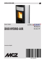
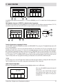
MCZ DUO HYDRO-AIR Guida d'installazione
- Categoria
- Stufe
- Tipo
- Guida d'installazione
Questo manuale è adatto anche per

INSTALLATION GUIDE EN
PELLET STOVE
DUO HYDRO-AIR
Instructions in English

II
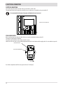
TABLE OF CONTENTS
TABLE OF CONTENTS ..................................................................................................II
INTRODUCTION ..........................................................................................................1
1WARNINGS AND WARRANTY CONDITIONS .................................................................2
2FUEL .......................................................................................................................7
3INSTALLATION .........................................................................................................8
4FLUE .......................................................................................................................9
5DRAWINGS AND TECHNICAL FEATURES .................................................................... 16
6INSTALLATION AND ASSEMBLY ...............................................................................18
7 HYDRAULIC CONNECTION ...................................................................................... 29
8ELECTRICAL CONNECTION.......................................................................................32
8PRECAUTIONS BEFORE STARTUP ...........................................................................33
9 CONTROL PANEL ...................................................................................................34
10 FIRST STARTUP .................................................................................................35
11 MENU STRUCTURE ..............................................................................................38
12 INFORMATION MENU ..........................................................................................42
13 SETTINGS MENU .................................................................................................45
14 TECHNICAL MENU ...............................................................................................59
15 SAFETY DEVICES AND ALARMS .............................................................................60
16 CLEANING AND MAINTENANCE ............................................................................65
17FAULTS/CAUSES/SOLUTIONS .................................................................................71
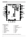
18CIRCUIT BOARD ...................................................................................................74

1
INTRODUCTION
Technical Dept. - All rights reserved - Reproduction is prohibited
Dear Customer,
our products are designed and manufactured in compliance with European reference Standards for construction products (EN13240
wood-burning stoves, EN14785 pellet-burning appliances, EN13229 replaces/wood-burning inserts, EN 12815 wood-burning cookers),
with high quality materials and extensive experience in the transformation processes. The products also meet the essential requirements
of Directive 2006/95/EC (Low Voltage) and Directive 2004/108/EC (Electromagnetic Compatibility).
To get the best performance, we suggest you read the instructions in this manual carefully.
This installation and use manual forms an integral part of the product ensure that the manual is always supplied with the appliance, even
if it changes owner. If the manual is lost, you can request another copy from the local technical service or download it directly from the
company website.
All local regulations, including those regarding national and European regulations, must be observed when the appliance is installed.
In Italy, for the installation of systems with biomass below 35KW, refer to ministerial decree D.M. 37/08, and the qualied installation
technician with the appropriate requisites must issue a certicate of compliance for the system installed. (By system one means
Stove+Chimney+Air inlet).
REVISIONS TO THE PUBLICATION
The content of this manual is strictly technical and the property of MCZ Group Spa.
No part of this manual may be translated into other languages and/or adapted and/or reproduced, even in part, in other mechanical or
electronic forms, photocopies, recordings or other, without the prior written authorisation from MCZ Group Spa.
The company reserves the right to make changes to the product at any time without prior notice. The proprietary company reserves its
rights according to the law.
CARE OF THE MANUAL AND HOW TO CONSULT IT
• Take care of this manual and keep it in an easily accessible place.
• Should the manual be misplaced or ruined, request a copy from your retailer or directly from the authorised Technical Assistance
Department. It can be downloaded from the company website.
• The "text in bold" must be read with particular care.
• “The "text in italics” draws attention to other sections in this manual or clarications.
• “NOTE” provides the reader with additional information.
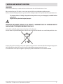
SYMBOLS USED IN THE MANUAL
CAUTION:
read the relative message carefully as failure to observe the information provided could result in serious
damage to the product and put the persons who use it at risk.
INFORMATION:
failure to comply with these provisions will compromise the use of the product.
OPERATING SEQUENCES:
sequence of buttons to be pressed to access the menus or change settings.
MANUAL
carefully read this manual or the relative instructions.

2
1-WARNINGS AND WARRANTY CONDITIONS
SAFETY PRECAUTIONS
• Installation, electrical connection, function test and maintenance must only be carried out by authorised and
qualied personnel.
• Install the product in accordance with all local and national legislation and regulations in force in the region or state.
• Only use the fuel recommended by the manufacturer. The product must not be used as an incinerator. It is strictly forbidden to use
liquid fuel.
• Do not put any fuel other than wood pellets in the hopper.
• The instructions provided in this manual must always be complied with to ensure the product and any electronic appliances
connected to it are used correctly and accidents are prevented.
• The user, or whoever is operating the product, must read and fully understand the contents of this installation guide before
performing any operation. Errors or incorrect settings can cause hazardous conditions and/or poor operation.
• Do not climb on or lean on the product.
• Do not put linen on the product to dry. Any drying racks or the like must be kept at a safe distance from the product. Fire hazard.
• All liability for improper use of the product is entirely borne by the user and relieves the Manufacturer from any civil and criminal liability.
• Any type of tampering or unauthorised replacement with non-original spare parts could be hazardous for the operator's safety and
relieves the company from any civil and criminal liability.
• Many of the surfaces of the product get very hot (door, handle, glass, smoke outlet pipes, etc.). Avoid coming into contact with
these parts, without adequate protective clothing or suitable implements, such as gloves with thermal protection or
"cold handle" operating systems.
• It is forbidden to operate the product with the door open or the glass broken.
• The product must be powered by an electrical system that is equipped with an eective earthing device.
• Switch the product o in the event of a fault or malfunction.
• Accumulated unburned pellets in the burner after each "failed start-up" must be removed before lighting again. Check that the
burner is clean and positioned properly before lighting again.
• Do not wash the product with water. Water could get inside the unit and damage the electrical insulation and cause electric shocks.
• Do not stand for a long time in front of the product in operation. Do not overheat the room you are in and where the product is
installed. This could cause injuries and health problems.
• Install the product in a location that does not present a re hazard and is equipped with power and air supplies and smoke extractors.
• In the event of re in the chimney, turn o the device, disconnect it from the mains electricity and do not open the hatch. Then
contact the competent authorities.
• The product and the cladding must be stored in a dry place and must not be exposed to weathering.
• It is recommended not to remove the feet that support the product in order to guarantee adequate insulation, especially if the
ooring is made of ammable materials.
• In the event of a malfunction of the ignition system, do not force it to light by using ammable materials.
• Special maintenance must only be performed by authorised and qualied personnel.
• Assess the static conditions of the surface on which the weight of the product will rest and provide suitable insulation if it is made of
ammable material (e.g. wood, tted carpet or plastic).

3
1-WARNINGS AND WARRANTY CONDITIONS
Technical Dept. - All rights reserved - Reproduction is prohibited
INFORMATION:
Please contact the retailer or qualied personnel authorised by the company to resolve a problem.
• You must only use the fuel specied by the manufacturer.
• When the product is switched on for the rst time it is normal for it to emit smoke due to the paint overheating for the rst time.
Therefore make sure the room in which it is installed is well ventilated.
• Check and clean the smoke extraction pipes regularly (connection to the chimney).
• The product is not a cooking appliance.
• Always keep the cover of the fuel hopper closed.
• Store this installation and use manual with care as it must accompany the product for the duration of its useful life. If the product is
sold or transferred to another user, ensure the manual is also handed over.
INTENDED USE
The product only works with wood pellets and must be installed indoors.
WARRANTY CONDITIONS
The company guarantees the product, with the exception of elements subject to normal wear listed below, for a period of 2 (two)
years from the date of purchase attested by:
• a document to serve as proof of purchase (invoice and/or receipt) that shows the name of the vendor and the date on which the
purchase was made;
• forwarding of the completed certicate of guarantee within 8 days of purchase.
Furthermore, in order for the guarantee to be valid, the device must be installed and calibrated by qualied personnel, and where
necessary, the user must be issued with a declaration of conformity and correct functioning of the product.
We recommend testing the product before completion with the relative nishes (claddings, painting of walls, etc.).
Installations that do not meet the current standards, improper use and lack of maintenance as expected by the manufacturer, void the
product warranty.
The guarantee is valid on the condition that the instructions and warnings contained in the use and maintenance manual are observed,
and therefore the product is used correctly.
The replacement of the entire appliance or the repair of one of its components does not extend the warranty period, and the original
expiry date remains unchanged.
The warranty covers the replacement or free repair of parts recognised as faulty at source due to manufacturing defects.
To benet from the warranty, in the event of a fault, the customer must have the warranty certicate and show it with the proof of
purchase document to the Technical Assistance Oce.

4
1-WARNINGS AND WARRANTY CONDITIONS
EXCLUSIONS
The guarantee does not cover malfunctions and/or damage to the appliance that arise due to the following causes:
• Damage caused during transportation and/or handling
• all parts that develop faults due to negligence or improper use, incorrect maintenance, installation that does not comply with the
manufacturer's instructions (always refer to the installation and use manual provided with the appliance)
• incorrect sizing with regard to the use or faults in the installation or failure to adopt the necessary devices to guarantee proper
execution
• improper overheating of the equipment, use of fuels not conforming to the types and quantities indicated in the instructions provided
• further damage caused by incorrect user interventions in an attempt to x the initial fault
• worsening of the damage caused by the user continuing to operate the appliance even after the fault has been noticed
• in presence of a boiler, any corrosion, incrustations or breakages caused by water ow, condensation, hardness or acidity of the water,
improperly performed descaling treatments, lack of water, mud or limescale deposits
• ineciency of chimneys, ues or parts of the system aecting the appliance
• damage caused by tampering with the appliance, atmospheric agents, natural disasters, vandalism, electric shocks, res, faults in
the electric and/or hydraulic system.
Also excluded from this guarantee are:
• parts subject to normal wear such as gaskets, glass, claddings and cast iron grids, painted, chrome-plated or gilded parts, handles
and electric cables, bulbs, indicator lights, knobs, all parts which can be removed from the hearth.
• Variations in colour of the painted or ceramic/serpentine parts and craquelure ceramics as they are natural characteristics of the
material and product use.
• masonry work
• plant parts (if present) not supplied by the manufacturer
Any technical interventions on the product to eliminate the defects mentioned above and consequent damages must be agreed upon with
the Technical Assistance Centre, who reserves the right to accept the relative appointment or not. However, said interventions will not be
carried out under the guarantee but as technical assistance to be granted as part of any eventual and specic agreed conditions and in
accordance with the fee applicable for the work to be carried out.
The user will also be charged for any costs incurred to remedy the incorrect technical interventions, tampering or damage to the appliance,
not attributable to original faults.
With the exception of the legal or regulatory limits, the warranty does not cover the reduction of atmospheric and acoustic pollution.
The company declines all liability for any damage which may be caused, directly or indirectly, to persons, animals or objects as
a consequence of non compliance with any provision specied in the manual, especially warnings regarding installation, use
and maintenance of the appliance.

5
1-WARNINGS AND WARRANTY CONDITIONS
Technical Dept. - All rights reserved - Reproduction is prohibited
SPARE PARTS
In the event of a malfunction, consult the retailer who will forward the call to the Technical Assistance Service.
Only use original spare parts. The retailer or service centre can provide all necessary information regarding spare parts.
We do not recommend waiting for the parts to get worn out before having them replaced. It is important to perform regular maintenance.
The company declines all liability if the product and any other accessory is used improperly or modied without
authorisation.
All parts must be replaced with original spare parts.
PRECAUTIONS FOR CORRECT DISPOSAL OF THE PRODUCT IN ACCORDANCE WITH THE EUROPEAN DIRECTIVE
2002/96/EC AND ITS SUBSEQUENT AMENDMENT 2003/108 EC.
At the end of its working life, the product must not be disposed of as urban waste.
It must be taken to a special dierentiated waste collection centre set up by the local authorities or to a retailer that provides this service.
Disposing of the product separately prevents possible negative consequences for the environment and health deriving from inappropriate
disposal and allows its materials to be recovered in order to obtain signicant savings in energy and resources.
As a reminder of the need to dispose of appliances separately, the product is marked with a crossed-out wheeled dustbin.

6
1-WARNINGS AND WARRANTY CONDITIONS
RULES FOR INSTALLATION
The product in question is a stove that uses wood pellets.
Below is a list of European regulations regarding the installation of the product:
EN 12828 Heating systems design.
IEC 64-8 Electrical systems with rated voltage not exceeding 1000 V AC and 1500 V DC.
EN 1443 General chimney regulation
EN 1856-1 metal smoke ducts
EN 1856-2 metal smoke extraction channels
EN 1457 chimneys - Interior terracotta / ceramic ues
EN 13384-1 Chimneys - Thermal and dynamic uid calculation methods - Part 1: Chimneys connected to a single appliance
Below are some applicable regulations for Italy:
UNI 10683:2012 Heat generators fuelled by wood or other solid bio-fuels - Test, installation, control and maintenance (for thermochemical
power at the rebox lower than 35kW)
UNI/TS 11278 general technical regulation for the choice of smoke duct/ue
UNI 10847:2000 Smoke extractor systems for liquid and solid fuelled generators - Maintenance and control - Guidelines and procedures
UNI 8065 water treatment in civil plants.
UNI 9182 Hot and cold (sanitary) water supply and distribution systems.
Installation must be carried out with reference to the diagram of the heating system prepared in accordance with the
standards and local recommendations in force:
In any case, respect:
For the heating appliance -
Local requirements concerning the chimney connection.
Local requirements for re-ghting standards.
For electrical parts - EN 60335 ''Safety of electrical household appliances and similar"
Part 1 - General requirements
Part 2 - Special regulations for appliances with gas, gas oil and solid fuel burners with electrical connections.

7
2-FUEL
Technical Dept. - All rights reserved - Reproduction is prohibited
The instructions contained in this chapter explicitly refer to the regulations of the Italian installation Standard UNI 10683. In any case,
always comply with the regulations in force in the country of installation.
PELLETS
Wood pellets are manufactured by hot-extruding compressed sawdust which is produced during the working of natural dried wood. The
compactness of the material is guaranteed by the lignin contained in the wood itself and allows pellets to be produced without glue or
binders.
The market oers dierent types of pellets with characteristics that vary according to the wood mixtures used. The diameter varies
between 6 and 8 mm, with a standard length ranging from 5 to 30 mm. A good quality pellet has a density of between 600 and 750 or
more kg/metres cubed and a water content that accounts for 5 to 8% of its weight.
Pellets have technical advantages besides being an ecological fuel, as the wood residue is used completely, thereby achieving cleaner
combustion than that of fossil fuels.
While good-quality wood has a caloric value of 4.4 kW/kg (15% moisture, after about 18 months of seasoning), whereas that of pellets
is around 4.9 kW/kg. To ensure good combustion, the pellets must be stored in a dry place and protected from dirt. Pellets are usually
supplied in 15 kg bags, therefore, storing them is very convenient.
Good quality pellets guarantee good combustion, thereby decreasing harmful emissions into the atmosphere.
The poorer the quality of the fuel, the more often the internal parts of the brazier and combustion chamber must
be cleaned.
The main quality certications for pellets currently available on the European market guarantee that the fuel complies with class A1/A2
according to EN14961-2. An example of these certications are the ENPlus, DINplus, Ö-Norm M7135, and they guarantee that they are
followed according to these characteristics:
• caloric value: 4,6 ÷ 5.3 kWh/kg.
• Water content: max 10% of weight.
• Percentage of ashes: max 1.5% of weight.
• Diameter: 5 ÷ 6 mm.
• Length: max 40 mm.
• Content: 100% untreated wood without the addition of binding substances (max 5% bark).
• Packaging: in sacks made from ecologically compatible or bio-degradable material.
The company strongly recommends using certied fuel for its products (ENplus, DINplus, Ö-Norm M7135).
Poor quality pellets or others that do not comply with the characteristics specied previously may compromise the
operation of your product and can therefore make the guarantee and product liability invalid.
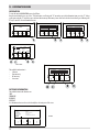
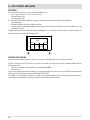
15 Kg BAG OF FUEL

B
A
8
3-INSTALLATION
FOREWORD
The installation position must be chosen according to the room, to the smoke extraction system, to the chimney ue. Check with local
authorities whether there are any restrictive regulations in force regarding the combustion air inlet, the smoke outlet system, the
ue or the chimney cap. The manufacturer declines all responsibility in the event of installations that do not comply with the laws in
force, incorrect room air exchange, electrical connection non-compliant with the standards and inappropriate use of the appliance. The
installation must be carried out by a qualied technician, who must issue a declaration of conformity of the system to the purchaser and
will assume full responsibility for nal installation and consequent good operation of the product.
In particular one must ensure that:
• there is a suitable combustion air inlet and smoke outlet in compliance with the type of product installed
• other stoves or devices installed do not cause depression in the room where the product is installed (for sealed appliances only, a
maximum of 15 Pa of depression in the room is allowed)
• when the product is switched on there is no reux of smoke in the room
• fumes extraction takes place in total safety (sizing, smoke seal, distances from ammable materials..).
We especially recommend checking the data tags of the ue for the safety distances that must be observed in presence
of combustible materials and the type of insulating material to be used. These indications must be followed strictly to
prevent serious harm to people and the integrity of the home. The installation of the appliance must ensure easy access to
clean the appliance itself, the smoke outlet pipes and the ue. It is forbidden to install the stove in rooms with a re hazard.
Installation in studio ats, bedrooms and bathrooms is only allowed with sealed or closed appliances equipped with
suitable combustion air ducting directly outside. Always maintain adequate distance and protection in order to prevent
the product from coming into contact with water.
In the event there are several appliances installed, the external air inlet must be sized accordingly.
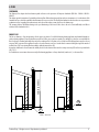
MINIMUM DISTANCES
It is recommended to install the stove detached from any walls and/or furniture, with a minimum clearance to allow eective aeration
of the appliance and a good distribution of heat in the room. Observe the distances from ammable or heat-sensitive objects (sofas,
furniture, wood panelling, etc..) as specied. The front distance from ammable materials must be at least 1 metre.
If particularly delicate objects are present, such as furniture, curtains or sofas, increase the stove clearance accordingly.
If the oor is made of wood, it is recommended to t a oor protection sheet in compliance with the Standards in
force in the country of installation.
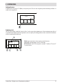
DUO HYDRO AIR
Non-ammable walls Flammable walls
A = 5 cm
B = 5 cm
A = 10 cm
B = 10 cm
If the oor is made of combustible material, it is recommended to use protection made of non-combustible material (steel, glass...) that
also protects the front from falling combusted material during cleaning operations.
The appliance must be installed on a oor with adequate load capacity.
If the existing construction does not meet this requirement, one must take appropriate measures (for example a load distribution plate).

min.3,5 metri
AT
(A)
AP
(B)
9
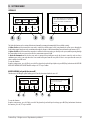
4-FLUE
Technical Dept. - All rights reserved - Reproduction is prohibited
FOREWORD
The Chimney Flue chapter has been drawn up with reference to the provisions of European Standards (EN13384 - EN1443 - EN1856 -
EN1457).
The chapter provides instructions for installing a chimney ue eciently and properly, but under no circumstances is it a substitute of the
Standards in force, which the qualied technician must be in possession of. Check with local authorities whether there are any restrictive
regulations in force regarding the combustion air inlet, the smoke outlet system, the ue or the chimney cap.
The company declines all liability relating to the poor functioning of the stove if this is due to the use of an insuciently sized ue in
violation of the Standards in force.
SMOKE FLUE
The ue or chimney is of great importance for the proper operation of a solid fuel-burning heating appliance with natural draught, as
modern heating appliances have high eciency with cooler ue gasses and consequently less draught, it is therefore essential that the
ue is built up to standard and always kept in perfect working order. A ue that serves a pellet/wood fuelled appliance must be at least
category T400 (or greater if the appliance requires so) and resistant to soot res. Smoke must be extracted through a single ue made of
insulated steel (A) or an existing ue that complies with the intended use (B).
A simple air shaft made of cement must be suitably lined. In both solutions there must be an inspection cap (AT) and/or inspection hatch
(AP) - FIG.1.
It is forbidden to connect more than one wood/pellet-burning appliance or of any other kind (vent hoods... ) to the same ue.
FIGURE 1 - SMOKE FLUE

A
B
C
D
E
A
B
C
D
15°
E
F
A
B
C
D
E
30°
F
10
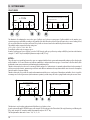
3-INSTALLATION
TECHNICAL CHARACTERISTICS
Have the eciency of the ue checked by an authorised technician.
The ue must be sealed against ue gasses, in a vertical direction without narrowing, be made with materials impermeable to smoke,
condensation, thermally insulated and suitable to resist normal mechanical stress over time (we recommend replaces made of A/316
or refractory material with insulated round section double chamber). Be suitably insulated externally to avoid condensation and reduce
smoke cooling. It should be separated from combustible or ammable materials with an air gap or insulating materials: check the
distance specied by the manufacturer of the replace according to EN1443. The chimney opening must be in the same room as the
appliance, or at most in the adjoining room, and have a soot and condensation collection chamber beneath the opening, and be accessible
via a watertight metal hatch.
FLAT ROOF
ROOF AT 15°
ROOF AT 30°
A = 0.50 metres
B = DISTANCE > 2 metres
C = DISTANCE < 2 metres
D = 0.50 metres
E = TECHNICAL VOLUME
A = MIN. 1.00 metres
B = DISTANCE > 1.85 metres
C = DISTANCE < 1.85 metres
D = 0.50 metres above highest
point
E = 0.50 metres
F = REFLUX AREA
A = MIN. 1.30 metres
B = DISTANCE > 1.50 metres
C = DISTANCE < 1.50 metres
D = 0.50 metres above highest
point
E = 0.80 metres
F = REFLUX AREA
FIGURE 2
FIGURE 3
FIGURE 4

A
B
D
60°
E
C
F
A
B
C
D
E
45°
F
11
3-INSTALLATION
Technical Dept. - All rights reserved - Reproduction is prohibited
ROOF AT 60° ROOF AT 45°
SIZING
The depression (draught) of a ue depends on its height. Check the depression with the values indicated in the technical characteristics.
The minimum height of the chimney is 3.5 meters.
The interior cross-section of the ue can be round (best), square or rectangular (the ratio between the internal sides must be ≤1.5) with
the sides joined with a minimum radius of 20 mm. The dimension of the cross-section must be minimum Ø100mm.
The cross sections/lengths of chimneys must be correctly sized in accordance with the general method of calculation of UNI EN13384-1 or
other methods of proven eciency.
Below is a list of some ues available on the market:
AISI 316 steel chimney with
double chamber insulated
with ceramic bre or
equivalent resistant up to
400°C.
Refractory chimney with
double insulated chamber and
external lightweight concrete
cladding with cellular material
such as clay.
Traditional square-section
clay chimney with insulating
empty inserts.
Avoid products with an
internal rectangular section
where the larger side is 1.5
times the smaller side (e.g.
20x40 or 15x30).
EXCELLENT GOOD POOR VERY POOR
A = MIN. 2.60 metres
B = DISTANCE > 1.20 metres
C = DISTANCE < 1.20 metres
D = 0.50 metres above highest point
E = 2.10 metres
F = REFLUX AREA
A = MIN. 2.00 metres
B = DISTANCE > 1.30 metres
C = DISTANCE < 1.30 metres
D = 0.50 metres above highest point
E = 1.50 metres
F = REFLUX AREA
FIGURE 5
FIGURE 6

1
9
9
2
3
4
5
6
7
8
9
12
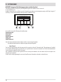
3-INSTALLATION
KEY:
(1) CHIMNEY CAP
(2) REFLUX CHANNEL
(3) SMOKE DUCT
(4) THERMAL INSULATION
(5) OUTSIDE WALL
(6) CHIMNEY CONNECTION
(7) SMOKE CHANNEL
(8) HEAT GENERATOR
(9) INSPECTION ACCESS PANEL
MAINTENANCE
The ue must be kept clean, since the deposit of soot or unburned oils reduces the cross-section reducing the draft and thus compromising
the ecient operation of the stove and, if large build-ups accumulate, can catch re. The ue and chimney must be cleaned and checked
by a qualied chimney sweep at least once a year. Once maintenance has been performed, request a written declaration that the system
is safe.
Failure to clean the system jeopardises safety.
CHIMNEY CAP
The chimney cap is a crucial element for the heating appliance to work properly: we recommend a wind proof chimney cap (A), see Figure
7.
The area of the openings for smoke
extraction must be at least double the
cross-section of the smoke duct/ue
system, and arranged so that smoke
extraction is ensured even in strong wind.
The chimney must prevent rain, snow or
animals from entering the chimney. The
height of outow into the atmosphere
must be beyond the reux area due to the
shape of the roof or any obstacles near the
outlet (see Figures 2-3-4-5-6).
CHIMNEY COMPONENTS
FIGURE 7
FIGURE 8

A
B B
A
C
MIN.1,5 m MIN.1,5 m
MIN.1,5 m
MIN.0,3 m
13
3-INSTALLATION
Technical Dept. - All rights reserved - Reproduction is prohibited
EXTERNAL AIR INLET
It is mandatory to provide an adequate external air intake that supplies the combustion air required for the product to work properly. The
ow of air between the outside and the installation room may be direct, through an inlet in an external wall of the room; or indirect, via
air intake from adjoining rooms and connecting permanently with the installation room (see Figure 9 b). Adjoining areas may not include
sleeping areas, garages or general areas with a re hazard. During installation one must check the minimum clearances required for air
intake from outside. Take into account the presence of doors and windows that could interfere with the proper ow of air to the stove
(see diagram below).
The air intake must have a minimum total net area of 80 cm2: the surface must be increased accordingly if within the room there are other
active generators (for example: electric fan for stale air extraction, kitchen hood, other stoves, etc...), which could cause a depression in
the room. One must verify that, with all the equipment on, the pressure drop between the room and the outside does not exceed a value
of 4 Pa. If necessary increase the intake section of the air inlet, which must be made at oor level and always protected with a bird-proof
outer protection grid and in such a way that it cannot be obstructed by any object.
It is possible to connect the air required for
combustion directly to the outside air inlet,
with a pipe of at least Ø50mm, with maximum
length of 3 linear metres; each pipe bend shall be
considered equivalent to a linear metre. To attach
the pipe see the back of the stove.
For stoves installed in studio ats, bedrooms and
bathrooms (where allowed), it is mandatory to
connect the combustion air outside. In particular
for sealed stoves the connection must be sealed
in order not to compromise the overall sealed
characteristic of the system.
FIGURE 9 A - DIRECTLY FROM OUTSIDE
FIGURE 10
FIGURE 9 B - INDIRECTLY FROM THE ADJACENT ROOM
A=AIR INLET
B=ROOM TO BE VENTILATED
C=INCREASE OF THE GAP UNDER THE DOOR

14
3-INSTALLATION
DISTANCE (metres) The air inlet must be at a distance of:
1.5 m UNDER Windows, doors, smoke outlets, cavities, ....
1.5 m HORIZONTALLY Windows, doors, smoke outlets, cavities, ....
0.3 m ABOVE Windows, doors, smoke outlets, cavities, ....
1.5 m AWAY from smoke outlet
CONNECTION TO THE FLUE
The connection between the ue and the appliance must be via a smoke duct that complies with EN 1856-2. The connecting section must
extend no more than 4 m horizontally, with a minimum slope of 3% and with a maximum of 3 90% bends (accessible for inspection - do
not count the T tting at the appliance outlet).
The diameter of the smoke duct must be equal to or greater than that of the appliance outlet (Ø 80 mm).
TYPE OF SYSTEM SMOKE DUCT
Minimum vertical length 1.5 metres
Maximum length
(with 1 accessible 90° bend)
6.5 metres
Maximum length
(with 3 accessible 90° bends)
4.5 metres
Maximum number of accessible 90° bends 3
Horizontal sections
(minimum slope 3%)
4 metres
Use a smoke duct according to current regulations in the country of installation that is compatible to product and installation characteristics.
The temperature class of the smoke duct must exceed operating temperatures of the appliance.
It is forbidden to connect several appliances to the same smoke duct, or the outlet from the overhead hoods. It is forbidden to extract the
combustion products directly through the wall, whether into indoor spaces or outdoors.
With ammable or heat-sensitive structures present, the smoke duct must respect the safety distances specied in the data plate.

T
I
S
I
U
B
A
P
U
I
I
C
4
3
D
2
I
E
V
U
1
F
15
3-INSTALLATION
Technical Dept. - All rights reserved - Reproduction is prohibited
EXAMPLES OF CORRECT INSTALLATION
1. Installation of Ø120mm ue with hole for the passage
of the pipe increased by:
minimum 100 mm around the tube if next to non
ammable parts such as cement, brick, etc.; or
minimum 300mm around the pipe (or as required by
data tags) if next to ammable parts such as wood etc.
In both cases, install suitable insulation between the
ue and the ceiling.
Always check and respect the data tags on the ue,
in particular the minimum safety distances from
combustible materials.
The previous rules also apply for holes made in walls.
2. Old ue, minimum pipe Ø100mm with the inclusion
of an external access door for chimney cleaning.
3. External ue made of insulated stainless steel pipes,
i.e. with double walls minimum Ø100mm: all securely
mounted on the wall. With wind-proof chimney cap. See
g. 7 type A.
4. Ducting system using T tting that allows easy access
for cleaning without having to remove the pipes
FIGURE 11
U = INSULATING
V = ANY REDUCTION FROM 100 TO 80 MM
I = INSPECTION CAP
S = INSPECTION ACCESS PANEL
P = AIR INLET
T = T JOINT WITH INSPECTION CAP
A = MINIMUM 40 MM
B = MAXIMUM 4 M
C = MINIMUM 3°
D = MINIMUM 400 MM
E = HOLE DIAMETER
F = SEE FIG.2-3-4-5-6

382
202
226
187
413
121310
417
64558
582
48
80
43
80
16
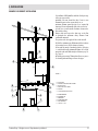
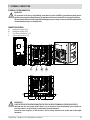
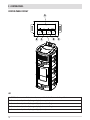
5-DRAWINGS AND TECHNICAL FEATURES
DRAWINGS AND CHARACTERISTICS
DUO HYDRO - AIR STOVE DIMENSIONS

17
5-DRAWINGS AND TECHNICAL FEATURES
Technical Dept. - All rights reserved - Reproduction is prohibited
TECHNICAL CHARACTERISTICS DUO HYDRO-AIR
Nominal output power 22.3 kW (19,178 kcal/h)
Nominal output power (H
2
O) 18.0 kW (15,480 kcal/h)
Minimum output power 4.4 kW (3,784 kcal/h)
Minimum output power (H
2
O) 3.0 kW (2,580 kcal/h)
Eciency at Max 92,5%
Eciency at Min 95,0%
Temperature of exhaust smoke at Max 160°C
Temperature of exhaust smoke at Min 71°C
Particles/OGC/Nox (13%O
2
) 2 mg/Nm3 - 0.2 mg/Nm3 - 132 mg/Nm3
CO at 13% O
2
at Min and at Max 0,040 – 0,012%
CO
2
at Min and at Max 7,03% - 12,49%
Smoke mass 12.6 g/sec
Max operating temperature 2.5 bar - 250 kPa
Recommended draught at Max power 0.10 mbar - 10 Pa
Recommended draught at Min power 0.05 mbar - 5 Pa
Hopper capacity 44 litres
Type of pellet fuel Pellet diameter 6-8 mm and size 5/30 mm
Pellet hourly consumption Min ~ 0.9 kg/h* - Max ~ 4.9 kg/h*
Autonomy At min ~ 28 h* - At max ~ 5 h*
Heatable volume m
3
481/40 – 550/35 – 642/30 **
Combustion air inlet Ø 50 mm
Smoke outlet Ø 80 mm
Air inlet 80 cm2
Rated electrical power (EN 60335-1) 120 W (Max 420 W)
Supply voltage and frequency 230 Volt / 50 Hz
Net weight 190 kg
Weight with packaging 200 kg
Distance from ammable material (back) 100 mm
Distance from ammable material (side) 100 mm
* Data that may vary depending on the type of pellets used
** Volume that can be heated, according to the power requirement per m
3
(respectively 40-35-30 Kcal/h per m
3
)
Tested according to EN 14785 in accordance with European regulation for Construction Products (UE 305/2011)

18
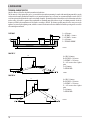
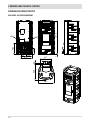
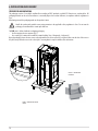
6-INSTALLATION AND ASSEMBLY
PREPARATION AND UNPACKING
The packaging consists of a recyclable cardboard box according to RESY standards, recyclable EPS foam inserts, wooden pallets. All
packaging materials can be reused for similar use or eventually disposed of as urban solid waste, in compliance with the regulations in
force.
After having removed the packaging make sure the product is intact.
Handle the product with suitable means paying attention to the applicable safety regulations in force. Do not turn the
packaging over and handle the ceramic parts with care.
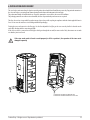
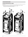
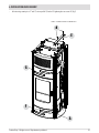
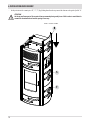
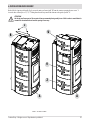
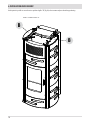
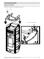
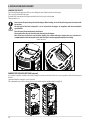
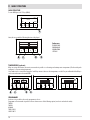
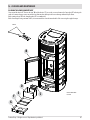
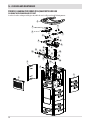
The DUO stove is delivered with two overlapping packaging:
• the rst contains the stove structure (g. 1).
• the second (g.2) contains the box with the ceramic cladding (1 top, 2 front panels, 6 side panels)
Open the packaging, remove the two screws on the right and the two screws on the left (see gure 4) that secure the base of the stove to
the pallet, and position the stove in the selected place, ensuring that it is complies with the above instructions.
FIGURE 1 - REMOVING PACKAGING
SCREWS
FIGURE 2 - CERAMIC PANEL
PACKAGING
La pagina si sta caricando...
La pagina si sta caricando...
La pagina si sta caricando...
La pagina si sta caricando...
La pagina si sta caricando...
La pagina si sta caricando...
La pagina si sta caricando...
La pagina si sta caricando...
La pagina si sta caricando...
La pagina si sta caricando...
La pagina si sta caricando...
La pagina si sta caricando...
La pagina si sta caricando...
La pagina si sta caricando...
La pagina si sta caricando...
La pagina si sta caricando...
La pagina si sta caricando...
La pagina si sta caricando...
La pagina si sta caricando...
La pagina si sta caricando...
La pagina si sta caricando...
La pagina si sta caricando...
La pagina si sta caricando...
La pagina si sta caricando...
La pagina si sta caricando...
La pagina si sta caricando...
La pagina si sta caricando...
La pagina si sta caricando...
La pagina si sta caricando...
La pagina si sta caricando...
La pagina si sta caricando...
La pagina si sta caricando...
La pagina si sta caricando...
La pagina si sta caricando...
La pagina si sta caricando...
La pagina si sta caricando...
La pagina si sta caricando...
La pagina si sta caricando...
La pagina si sta caricando...
La pagina si sta caricando...
La pagina si sta caricando...
La pagina si sta caricando...
La pagina si sta caricando...
La pagina si sta caricando...
La pagina si sta caricando...
La pagina si sta caricando...
La pagina si sta caricando...
La pagina si sta caricando...
La pagina si sta caricando...
La pagina si sta caricando...
La pagina si sta caricando...
La pagina si sta caricando...
La pagina si sta caricando...
La pagina si sta caricando...
La pagina si sta caricando...
La pagina si sta caricando...
La pagina si sta caricando...
La pagina si sta caricando...
La pagina si sta caricando...
La pagina si sta caricando...
-
 1
1
-
 2
2
-
 3
3
-
 4
4
-
 5
5
-
 6
6
-
 7
7
-
 8
8
-
 9
9
-
 10
10
-
 11
11
-
 12
12
-
 13
13
-
 14
14
-
 15
15
-
 16
16
-
 17
17
-
 18
18
-
 19
19
-
 20
20
-
 21
21
-
 22
22
-
 23
23
-
 24
24
-
 25
25
-
 26
26
-
 27
27
-
 28
28
-
 29
29
-
 30
30
-
 31
31
-
 32
32
-
 33
33
-
 34
34
-
 35
35
-
 36
36
-
 37
37
-
 38
38
-
 39
39
-
 40
40
-
 41
41
-
 42
42
-
 43
43
-
 44
44
-
 45
45
-
 46
46
-
 47
47
-
 48
48
-
 49
49
-
 50
50
-
 51
51
-
 52
52
-
 53
53
-
 54
54
-
 55
55
-
 56
56
-
 57
57
-
 58
58
-
 59
59
-
 60
60
-
 61
61
-
 62
62
-
 63
63
-
 64
64
-
 65
65
-
 66
66
-
 67
67
-
 68
68
-
 69
69
-
 70
70
-
 71
71
-
 72
72
-
 73
73
-
 74
74
-
 75
75
-
 76
76
-
 77
77
-
 78
78
-
 79
79
-
 80
80


MCZ DUO HYDRO-AIR Guida d'installazione
- Categoria
- Stufe
- Tipo
- Guida d'installazione
- Questo manuale è adatto anche per
in altre lingue
- English: MCZ DUO HYDRO-AIR Installation guide
Documenti correlati

Altri documenti
-
Ravelli Olimpia Use and Maintenance Manual
-
La Nordica CLEO COMBI Bordeaux Manuale del proprietario
-
-
Piazzetta P957 Instructions For Installation, Use And Maintenance Manual
-
-
RIKA MultiAir SONO AH Assembly Instructions Manual
-
RIKA INTERNO Assembly Instructions Manual
-
 Kalor 20B Manuale utente
-
-
 Unical itER Manuale utente

