Hitachi 42PMA400E Manuale utente
- Categoria
- TV al plasma
- Tipo
- Manuale utente
Questo manuale è adatto anche per

USER MANUAL
MANUEL UTILISATEUR
BEDIENUNGSANLEITUNG
MANUAL DE USUARIO
MANUALE D'USO
READ THE INSTRUCTIONS INSIDE CAREFULLY.
KEEP THIS USER MANUAL FOR FUTURE REFERENCE.
For future reference, record the serial number of your monitor.
SERIAL NO.
The serial number is located on the rear of the monitor.
This monitor is ENERGY STAR ® compliant when used with a
computer equipped with VESA DPMS.
The ENERGY STAR ® emblem does not represent EPA endorsement
of any product or service.
As an ENERGY STAR ® Partner, Hitachi,Ltd. has deter
mined that this product meets the ENERGY
STAR ® guidelines for energy efficiency.
Color Plasma Display Monitor
Model
PD1
42PMA400E
CMP4202E
CMP4121HDE
The stand is an option.
Le socle est en option.
Der Stander ist Sonderzubehor.
Il supporto di appoggio è un accessorio opzionale.
El soporte es opcional.

ENGLISH
USER'S MANUAL
Thank you very much for purchasing the HITACHI Plasma Display
Monitor.
Before using your monitor, please carefully read the "SAFETY
GUIDELINES" and this "USER'S MANUAL" so you will know how to
operate the monitor properly. Keep this manual in a safe place. You
will find it useful in the future.
Notes on lnstallation Work:
This product is marketed assuming that it is installed by qualifed
personnel with enough skill and competence. Always have an
installation specialist or your dealer install and set up the product.
HITACHI cannot assume liabilities for damage caused by mistake
in installation or mounting, misuse, modification or a natural
disaster.
Note for Dealers:
After installation, be sure to deliver this manual to the customer
and explain to the customer how to handle the product.

Large-screen, high-definition plasma display
panel
The 42-inch color plasma display panel, with a resolution of 1024 (H)
x 1024(V) pixels, creates a high-definition, large-screen (aspect ratio
: 16:9) and low-profile flat display. Free from electromagnetic
interferences from geomagnetic sources and ambient power lines,
the panel produces high-quality display images free from color
misconvergence and display distortion.
Multimedia input support
Two mini D-sub terminals have been provided for RGB input. It is
possible to switch between RGB signals and component signals*
from the Menu screen; therefore, use is possible with equipment
ranging from personal computers to imaging devices. A speaker
output terminal has also been provided.
* It is possible when the VIDEO unit of an option is inserted.
Multiscan converter and Flexible Control LSI
A wide range of personal computer signals can be handled, from 640
x 400, 640 x 480 VGA to 1600 x 1200 UXGA.
Easy-to-use remote controller and on screen
display system
The remote controller included eases the work of setting display
controls. Further, the on-screen display system, displays the status of
signal reception and display control settings in an easy-to-view
fashion.
Power saving system
The International ENERGY STAR® power saver feature saves power
consumption automatically when input signals are not available.
When connected to a VESA DPMS-compliant PC, the monitor cuts its
power consumption while it is idle.
About the Optional Video Unit
The following functions can be obtained by connecting the optional
video unit.
(1) A composite/S terminal and component terminal have been
added. A composite video output terminal is also provided for use
as a loop-through function.
(2) A wide range of devices other than personal computers can also
be connected.
(3) A component input is attained at a D-Sub terminal (RGB1, RGB2).
(4) The SCART signal of the European standard becomes possible.
Options
Ask your local retail dealer for further details.
1. Desktop stand: CMPAD05
2. Wall-mount unit:
Horizontal mount: CMPAK05
Vertical/horizontal mount: CMPAK15
These are brackets used to mount this device on a wall.
3. Ceiling-suspension unit: CMPAT05
4. Plasma monitor speaker: CMPAS04 (width:10.2mm)]
This is a two-way speaker with one 2.5cm dome type tweeter and
two 8cm round type woofers.
5. Video unit: CMPAV14
An expansion unit for viewing video with this device.
FEATURES CONTENTS
FEATURES ....................................................2
SAFETY GUIDELINES ..................................3
STANDARD ACCESSORIES ..........................7
Component Names ......................................8
Main Unit..............................................................................8
Remote controller ................................................................9
Loading Batteries ................................................................9
Handling the Remote Controller ..........................................9
INSTALLATION INSTRUCTIONS ................10
Installation..........................................................................10
Anti-tumble measures........................................................10
Connecting to a PC ..........................................................11
Connecting to a Video Imaging Device ............................12
Power Cord Connection ....................................................13
Mounting the Video Unit ..................................................13
Mounting the Speaker Unit ..............................................13
OPERATING INSTRUCTIONS ....................14
Turning Power On and Off ................................................14
Input Switching ..................................................................15
Volume Adjustment............................................................15
Audio Mute ........................................................................15
Size Switching ..................................................................16
Displaying Two Screens ....................................................16
Input Signal Screen Display ..............................................16
Automatic Adjustment of Screen Position and the Clock ..17
Independent Operation of Multiple Monitors ....................17
Using the Menu Screen ....................................................17
PICTURE MENU ................................................................18
SOUND MENU ..................................................................19
DISPLAY MENU ................................................................20
FUNCTION MENU ............................................................22
OTHER MENU ..................................................................23
OTHER FEATURES ....................................24
Automatic Store ................................................................24
Signal Check ....................................................................24
Power Save Mode..............................................................25
TWO SCREEN TABLE..................................25
IMAGE RETENTION OF PLASMA DISPLAY
......26
NOTES ........................................................26
TROUBLESHOOTING ..................................27
Symptoms That Seemingly Appear to be Failures ............27
Actions to Correct Abnormal Displays ..............................29
PRODUCT SPECIFICATIONS ......................30
Signal Input........................................................................31
Recommended Signal List ................................................31
Notes about This Manual
• The information in this manual is subject to change without notice.
• While meticulous care has been taken in the preparation of this manual, you are requested to notify your dealer or us should you have any
comments, views or questions about our product.
• Fully understand the prerequisites to using the product, such as hardware and software specifications and constraints, in using the
product. We are not held liable for damages caused by improper handling of the product.
• Reproduction of this manual in whole or in part without our prior written permission is prohibited.
• The product names mentioned in this manual may be trademarks or registered trademarks of their respective owners.

ENGLISH
SAFETY GUIDELINES
This monitor is designed to be safe to use. However, fire or serious injury may occur unless you use this monitor in the proper way.
Please follow the instructions shown below in order to avoid injury.
Keep the safety guideline
Do not use the monitor if it fails
If you find something unusual ,
* If smoke comes out,
* If there is a strange smell,
* If water enters the case,
* If you drop the monitor or damage the cabinet,
(1) Turn off the monitor
(2) Disconnect the power plug from the mains
(3) Request repair
Warning and Caution are indicated in this guide and monitor itself.
Fire or electric shock may cause death or serious injury unless you follow the instruction.
Electric shock or other accidents may cause serious injury or damage of your properties.
CAUTION
Fire or electric shock may cause death or serious injury unless you follow the instruction below.
WARNING
• If something smells strange or smoke comes from the monitor:
Turn off the monitor and disconnect the power plug from the mains immediately.
Contact service center after confirming that the smoking has stopped.
If you continue to operate the monitor with such abnormal condition, it may cause fire or you may receive an electric shock.
• Do not drop water or a foreign substance on to the monitor.
If you drop water or a foreign substance on to the monitor, it may cause fire or an electric shock.
If it happens turn off the monitor and disconnect the power plug from the mains and ask service center for instruction.
• Do not put the monitor on an unstable place.
If you put the monitor on an uneven or unstable place, it may fall down and you may be injured.
Put the monitor on a flat surface strong enough to take the weight.
• Do not apply shock to the monitor.
• Do not use monitor if glass is broken or damaged.
If there is no picture appearance, broken glass , smoking or something smells after applying shock to the monitor, turn off the monitor and
disconnect the power plug from the mains immediately. Then, call the service center.
If you continue to operate the monitor with such abnormal conditions, it may cause fire or you may receive an electric shock.
• Do not disassemble or modify the monitor.
There is high voltage portion inside of the monitor. Disassembling or modification of the monitor may cause fire or electric shock.
• Do not use the monitor in wet environment.
If you use the monitor in a wet place such as bath or shower room, it may cause fire or electric shock.
• Do not damage or modify the power cord.
If you put something heavy on the power cord or pull, squeeze, heat the cord, it may be damaged and it may cause fire or electric shock.
If the power cord is damaged, call service center.
WARNING

SAFETY GUIDELINES(continued)
Fire or electric shock may cause death or serious injury unless you follow the instruction.
WARNING
• The enclosed power cord must be used!
Failure to do so may cause electric shock hazard or fire hazard.
In USA/Canada, use a UL LISTED/CSA LABELLED or CERTIFIED power cord set meeting the following specifications :
Rating: min. 125V, 10A , Length: max. 3.0m , Type: SVT or SJT
Plug type: NEMA 5-15P figure, Parallel blade, Grounding type
In Europe or 200V area, a proper European standard approved power cord is to be used with this monitor.
For a rated current up to 6 A, a type not lighter than H05VV-F 3G 0.75 mm
2
or H05VVH2-F 3G 0.75 mm
2
must be used.
• Use only the correct voltage power outlet with safety ground connection!
100 - 120 V for USA, Canada, etc.
200 - 240 V for Europe, etc.
(This monitor will automatically adjust to the input voltage 100 - 120 / 200 - 240V.)
• Be careful of power cord connection!
Before inserting the plug of the power cord into a socket of the correct voltage, check that the connection portion of the power cord is clean
(with no dust). Then, insert the plug of power cord into the socket firmly, otherwise it may cause electric shock or fire hazard.
• Do not touch the power plug when lightning is close to you.
You may receive an electric shock.
• Do not touch the power plug with wet hands.
You may receive an electric shock.
• Do not obstruct a ventilation hole.
If you obstruct a ventilation hole during the operation of the monitor or just after switching off the power, it may cause a fire or electric shock
due to heating up the monitor.
• Do not put the monitor screen side up.
• Do not put the monitor on a shelf or in a cabinet without adequate ventilation of 4 inches top, sides, bottom and rear.
• Do not put the monitor on a carpet or mattress.
• Do not cover the monitor with a cloth.
• FOR THE CUSTOMERS IN THE U.K.
THIS PRODUCT IS SUPPLIED WITH A TWO PIN MAINS PLUG FOR USE IN MAINLAND EUROPE. FOR THE U.K. PLEASE REFER TO THE
NOTES ON THIS PAGE.
IMPORTANT FOR UNITED KINGDOM
WORDING FOR CLASS I EQUIPMENT INSTRUCTION BOOKS AND LABELS
The mains lead on this equipment is supplied with a molded plug incorporating a fuse, the value of which is indicated on the pin face of the
plug. Should the fuse need to be replaced, an ASTA or BSI approved BS 1362 fuse must be used of the same rating. If the fuse cover is
detachable never use the plug with the cover omitted. If a replacement fuse cover is required, ensure it is of the same colour as that visible on
the pin face of the plug. Fuse covers are available from your dealer.
DO NOT cut off the mains plug from this equipment. If the plug fitted is not suitable for the power points in your home or the cable is too short to
reach a power point, then obtain an appropriate safety approved extension lead or consult your dealer.
Should it be necessary to change the mains plugs, this must be carried out by a competent person, preferably a qualified electrician.
If there is no alternative to cutting off the mains plug, ensure that you dispose of it immediately, having first removed the fuse, to avoid a possible
shock hazard by inadvertent connection to the mains supply.
WARNING: THIS EQUIPMENT MUST BE EARTHED
IMPORTANT
The wires in the mains lead are coloured in accordance with the following code :
Green and Yellow = Earth, Blue = Neutral, Brown = Live.
As these colours may not correspond with the coloured markings identifying the terminals in your plug, proceed as follows:
The wire which is coloured GREEN and YELLOW must be connected to the terminal in the plug which is marked with the letter E or by the earth
symbol or coloured GREEN or GREEN and
YELLOW.
The wire coloured BLUE must be connected to the terminal marked with the letter N or coloured BLUE or BLACK. The wire coloured BROWN
must be connected to the terminal marked with the letter L or coloured BROWN or RED.
Brown to Live
Fuse
Cord Clamp
Green & Yellow
to Earth
Blue to Neutral

ENGLISH
Electric shock or other accidents may cause serious injury or damage to your property.
CAUTION
• Disconnect the power plug from the mains when you move the monitor.
Moveing the monitor without disconnecting the power plug from the mains may damage the cord and cause a fire or electric shock. You are
advised to move the monitor with two persons.
Handle with care when you move the monitor, particularly take care of glass screen.
• When you disconnect the power plug.
You have to grasp the power plug itself, do not pull the power cord.
If you pull the power cord, you may damage it and it may cause a fire or an electric shock.
Do not touch the power plug just after disconnecting it from the mains or you may receive electric shock.
• Disconnect the power plug from the mains when you don't use the monitor for a long time.
This is for your safety.
• Do not put the monitor in atmosphere with soot, steam, high humidity, and dust.
It may cause a fire or electric shock.
• Do not put the monitor in high temperature atmosphere.
Do not put the monitor in the place exposed to the direct rays of the sun for a long period of time. Heat may cause a fire, transformation, or
melting of the monitor.
• Do not put things on the monitor.
Do not put things on the monitor or give some shock to the monitor.
The monitor may fall down or drop from a desk. And it may cause injury.
SAFETY GUIDELINES(continued)
• Do not coil or wind the power cord.
This may cause excessive heat resulting in a fire.
• Caution for 200 - 240V operation only
This equipment relies on the protective devices in the building installation for short - circuit and over - current protection. Refer to the following
table for the suitable number and location of the protective devices which should be provided in the building installation.
INFORMATIVE EXAMPLES OF PROTECTIVE DEVICES IN SINGLE - PHASE
EQUIPMENT OR SUB - ASSEMBLIES
Verify that the protective devices in the building installation meets the conditions in the table prior to installing the equipment.
• Remove the power cord for complete isolation!
For complete isolation from the mains, remove the power cord from the monitor or from the wall socket.
Protection
against
Minimum number
of fuses or circuit -
breaker poles
Location
Case A: Equipment to be connected to
POWER SYSTEMS with earthed neutral
reliably identified, except for Case C below.
Earth faults 1 Phase conductor
Overcurrent 1 Either of the two conductors
Case B: Equipment to be connected to any
supply, including IT POWER SYSTEMS and
supplies with reversible plugs, except for
Case C below.
Earth faults 2 Both conductors
Overcurrent 1 Either of the twoconductors
Case C: Equipment to be connected to 3 -
wire power systems with earthed neutral
reliably identified.
Earth faults 2 Each phase conductor
Overcurrent 2 Each phase conductor
You may have serious injury or your property may be damaged unless you follow the instruction below.
CAUTION

PRECAUTIONS
SAFETY GUIDELINES(continued)
• Installation environment
Do not obstruct a ventilation hole.
Do not put the monitor on carpet or blanket, or near a curtain which has a possibility of obstructing a ventilation hole of the monitor.
Do not put the monitor in the following places.
• Hot places such as near heater, place exposed to the direct rays of the sun.
• A place where the temperature is widely changing.
• Places with soot, dust or high humidity.
• Poor air ventilation place.
• Place near fire.
• A wet place such as bathroom, or shower room.
• Place where you can trip over it.
• Always vibrating or strongly vibrating places.
• Distorted or unstable places.
• How to view the monitor.
If you use the monitor in too dark a room, your eyes may become tired.
Please use it in a reasonably bright room.
Avoid direct rays of the sun to the screen in order to prevent eye fatigue.
Your eyes will get fatigued after viewing the monitor for long period of time.
Relax your eyes by viewing away from the monitor from time to time.
Please watch the monitor in downward direction.
• Note on image retention
The plasma monitor illuminates phosphor to display images. The phosphor has a finite illumination life. After extended periods of illumination,
the brightness of the phosphor would be degraded to such extent that still images would image retention that part of the screen as grayed-out
images.
Tips to prevent such image retention are:
- Do not display images having sharp brightness differences or high-contrast images, such as monochrome characters and graphic patterns,
for long.
- Do not leave stationary images appearing for long, but try to refresh them at appropriate intervals of time, or try to move them using screen
saver function.
- Turn down the contrast and brightness controls.
• How to clean the monitor.
Before cleaning the monitor, turn off the monitor and disconnect the power plug from the mains.
When cleaning the monitor, do not spray directly the screen or cabinet with cleaner.
Use a clean, dust free, dry and soft cloth. If it is not enough, then use a cloth with non-alcoholic or non-ammonia detergent.
Do not rub the surface of the screen with ball-point-pen or screw-driver etc.
• Prevention of an obstacle to Radio receivers
This monitor has been designed pursuant to the EN55022 class B Rules. This is to prevent a problem to Radio receivers.
- Keep the monitor away from Radio.
- Adjust Radio antennas in order for the monitor not to receive interference.
- The antenna cable of Radio should be kept away from the monitor.
- Use a coaxial cable for antenna.
You can check if this monitor influences Radio receivers by turning off all other equipment other than the monitor.
If you find a problem receiving Radio when using the monitor, check the instructions mentioned above.
• Precautions for the monitor
- Use the attached signal-cable when you connect the monitor with PC equipment.
Do not use other signal-cables.
- Confirm the connector is fixed tightly when the signal cable is connected.
Also confirm the screws on the connector are tightened.
- Plug the power cord of the monitor into a different socket from that for other equipment, such as Radio etc..
- Use a plug with ground terminal and make sure that it connects to the ground.
• Precaution during transportation
Please pay attention when you transport this monitor because it is heavy.
Furthermore, use the original carton box and its packaging materials when the monitor is transported.
Failure to transport the monitor in any carton except the original carton may result in damage to the monitor.
Save the original carton box and all packing material.

ENGLISH
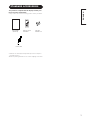
This product is complete with the display monitor, plus
the accessories shown below.
• If any of these accessories is missing, please contact your dealer.
• Read the user manual (this book) and keep them in a safe place
for handy reference.
•Retain the packing materials for use in future shipping or relocation.
User manual
(this book)
Power cable
Remote-control
transmitter
AUTO PinP SIZE
MUTE VOL
VOL
RECALL
RGB 1 RGB 2
ENTER
VIDEO 1 VIDEO 2
MENU RETURN
ID
ID SET
Size AA
batteries x 2
STANDARD ACCESSORIES

Caution when moving the main unit
• As this product is heavy, whenever it is moved, two
people are required to transport it safely.
• Whenever the unit is moved it should be lifted forwards
using the two handgrips at the back, and the unit should
then be held at the base on both sides for stability.
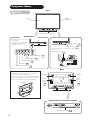
Component Names
Front
Cabinet
(front frame)
The stand shown is optional.
Panel
Remote-control
receiver
SIZE button
INPUT SELECT button
RECALL button
• Adjustment buttons are located
on the bottom.
• The back cover is provided with
indications to distinguish the
adjustment buttons.
SUB-POWER button
Control panel
VOLUME button
Main power switch
• The main power switch is located at the back, on the
lower surface.
Indicator lamp
External device connection terminals
Rear
RS232C
RGB 2
D-SUB IN
RGB 1
D-SUB IN
AUDIO IN
RGB input terminals
External
speaker
terminals
Handgrips
HandgripsHandgrips
Main Unit
External
speaker
terminals

ENGLISH
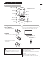
Remote controller
AUTO PinP SIZE
MUTE VOL
VOL
RECALL
RGB 1 RGB 2
ENTER
VIDEO 1 VIDEO 2
MENU RETURN
ID
ID SET
ID SET button
POWER OFF button
POWER ON button
POWER ON/OFF button
MENU button
MUTE button
RGB/VIDEO buttons
VOLUME UP/DOWN button
RETURN button
RECALL button
AUTO button
PinP button
SIZE button
ID button
SELECT/ADJUST buttons
ENTER button
Loading Batteries
1. Open the battery cover.
• Slide back and remove the battery
cover in the direction of the arrow.
2. Load batteries.
• Load two Size AA batteries included observing the correct
polarities.
3) Close the battery cover.
• Replace the battery cover in the direction of the arrow and snap
it back into place.
Use the remote controller within about 5 m from front of the unit’s
remote-control sensor and within 30 degrees on both sides.
AUTO PinP SIZE
MUTE VOL
VOL
RECALL
RGB 1 RGB 2
ENTER
VIDEO 1 VIDEO 2
MENU RETURN
ID
ID SET
With in 30
degrees
About 5m
About 3m
With in 30
degrees
About 3m
• Do not use new and old batteries together. The batteries could
explode or leak, resulting in fires, physical injury, or stains.
• When loading batteries, observe their correct polarities as
marked on the product. If loaded in the wrong direction, the
batteries could explode or leak, resulting in fires, physical injury,
or stains.
CAUTIONS
TIPS
• Do not drop or impact the remote controller.
• Do not splash the remote controller with water or put it on a wet
object to avoid possible failures.
• Before leaving the remote controller out of use for an extended
period of time, remove the batteries from it.
• If the remote controller begins to lack responsiveness, replace
the batteries.
• Strong light such as direct sunlight impinging on the
photoreceptor of the remote control can cause operational
failure. Position this unit to avoid direct contact with such light.
Handling the Remote Controller
Component Names (continued)

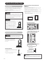
Anti-tumble measures
Securing to a wall or pillar
Using a commercially available cord,
chain and clamp, secure the set to a firm
wall or pillar.
Securing desktop
1)Using wood screws (two), fasten the set to the
clamping screw holes on the rear of the stand
as shown.
2)Using commercially available wood screws,
secure the set firmly in position.
No stand is provided with this product. When installing the monitor,
use the optional Desk-top Stand (CMPAD05), Wall Mount Unit
(horizontal-mount CMPAK05, vertical/horizontal-mount CMPAK15),
or Ceiling Mount Unit (CMPAT05).
The Desk-top Stand has been used for the illustrations in this
manual.
Using the optional vertical-mount unit
(CMPAK15)
Using the optional wall-mount unit (CMPAK15) allows set to mount
on wall surfaces as shown at below.
1) Make at least four sets of commercial anchor bolts and screws
available to meet various kinds of walls to mount on.
2) Read the instructions supplied with the wall-mount unit carefully to
optimally locate the plasma display on a wall surface.
3) Prepare the wall surface for anchoring and drilling as needed, as
shown in the sketches.
• Make sure that an adequate wall surface strength and a screw
holding strength are available.
SPEAKER
TERMINAL
8 8W
SPEAKER
TERMINAL
8 8W
Horizontal mounting
Upper left vertical mounting
Plasma display outline
Wall surface
Anchor bolt
Hold to 25 mm
(1 inch) or below.
SPEAKER
TERMINAL
8 8W
SPEAKER
TERMINAL
8 8W
Driving anchor bolts into
a wall surface
Plasma display outline
Side view
INSTALLATION INSTRUCTIONS
Installation
• Installation of the wall mount unit and
ceiling mount unit can be dangerous, so
do not attempt this work yourself. Ask your
dealer to provide the name of a qualified
installer.
• In order to prevent an internal temperature
increase, maintain a space of 10cm (4
inches : For a desktop set-up) or more
between the sides and other objects such
as walls, etc., so that the ventilation holes
are not blocked.*
CAUTIONS
Have this unit mounted in a stable place. Take measures to
prevent it from tumbling down to avoid possible physical injury.
CAUTIONS
Horizontal mounting Upper left vertical
mounting
Indicating lamp
The mounted unit should have the indicating lamp at its bottom.
Otherwise, an elevated internal temperature rise could cause the
unit to fail or fire.
CAUTIONS
Cord
or
chain
Clamp
10cm (4 inches) or more*
Deux endroits
Vis bois
Cord
or
chain
Clamp
10cm (4 inches) or more*
Use one of the special mount units to install this product. A mount
of insufficient strength or inadequate design can cause overturning
or dropping and result in fire, electrical shock or injury. Please
note that our company assumes absolutely no responsibility for
personal injuries or property damage caused by use of other
mount units or improper installation.
WARNING

Read SAFETY GUIDELINES ( to ) carefully to ensure maximum safety before
proceeding to these steps:
• Choose an appropriate site and install the product on a level table where the stand is secure.
• Install the monitor to have ready access to a power socket available.
• Make sure that the power switch of this device is turned off.
(1) Make sure that the display signal of the personal computer to be used is compatible with the specifications of this
device.
• See "Product Specifications" concerning the specifications of this device.
(2) Make sure that the power switch of the personal computer is turned off.
(3) Connect the signal input terminal (RGB 1 or RGB 2) on the rear panel of this device to the display signal output
terminal of the personal computer.
• Use a cable that fits the input terminal of this device and the output terminal of the personal computer.
• Depending on the type of personal computer being connected, the use of an optional conversion adapter or the adapter provided with
the personal computer may be necessary in some cases. For details, refer to the instruction manual of the personal computer or ask the
personal computer manufacturer or your local retail dealer.
ENGLISH
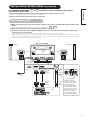
Connecting to a PC
INSTALLATION INSTRUCTIONS (continued)
RS232C
RGB 2
D-SUB IN
RGB 1
D-SUB IN
AUDIO IN
Monitor rear panel
Power
cable
Power cable
connector
PC
Speaker (R)
Speaker (L)
To signal
input
terminals
To audio input terminals
To signal
output
terminal
To audio
output
terminal
3.5mm
Stereo
mini jack
Cord Clamper
When connecting a
computer audio input to
the unit (using a 3.5mm
stereo mini jack), the
cord must pass through
the cord clamp toward
the bottom of the back of
the main unit. If it does not,
there is a possibility of
insufficient suppression of
electromagnetic radiation.

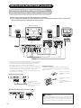
Connecting to a Video Imaging Device
(When the optional video unit is installed.)
INSTALLATION INSTRUCTIONS (continued)
Use if the
video
equipment
has an
S video
input terminal
Monitor rear panel
Speaker (R)
Speaker (L)
External Monitor
Power cable
connector
AUDIO IN COMPONENT IN
COMPOSITE
IN INOUT
VIDEO 2
P
R/CR PB/CB
Y
S
R
R
VIDEO 1
L/MONO
L/MONO
COMPOSITE
IN INOUT
S
Power
cable
To S video output
terminals
To S video input
terminals
To audio/video
output terminals
To audio output
terminals
To component
output terminals
To component
input terminals
To audio input
terminals
Video equipment
(such as a video disc player,
a DVD player, and a video camera)
To composite
input terminals
To composite
output terminals
• If video equipment with an S video output terminal is used, cabling by
the S video cable is recommended to provide finer video quality. (If
an S video input terminal and a video input terminal connect to the
monitor at the same time, S video input would govern.)
• If the VIDEO1 OUT terminal is connected to an external monitor with a
75 Ohm terminal, it is possible to view the same image as on the main
unit. If an external monitor is not being used, the cable must be
removed from the VIDEO OUT terminal. The image will appear white
as saturation level is reached.
With RGB component setup
Speaker Connection
This device is equipped with speaker output jacks for use in
connecting a speaker system (optional). Refer to the diagram
below to connect.
Remove the insulation
and twist the bare cable
as shown.
Down the tab and insert
the cable.
Press the tab up to
prevent the cable being
pulled out.
10
(1) Make sure that the power switch of the imaging device is turned off.
(2) Use a commercially available cable and connector to connect the signal input terminal on the rear panel of this
device and the signal output terminal of the imaging device.
When connecting speakers, connect the plus (+) speaker terminal
and the plus (+) speaker terminal of this device, and connect the
respective minus (-) terminal in the same way. The sound will not
be correct if plus (+) and minus (-) terminal are connected to each
other.
CAUTIONS
RS232C
RGB 2
D-SUB IN
RGB 1
D-SUB IN
AUDIO IN
To component video
equipment.
Please use the connection cable
suitable for the terminal form of
video equipment.
With SCART terminal connection (refer to )
AUDIO IN COMPONENT IN
COMPOSITE
IN INOUT
VIDEO 2
P
R/CR PB/CB
Y
S
R
R
VIDEO 1
L/MONO
L/MONO
Video equipment

ENGLISH
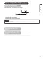
(1) Connect the power cord to this device.
(2) Connect the power cord plug to the power outlet.
Connect the power cord, after completing all other connections.
Refer to the respective instruction manuals concerning mounting of the optional video unit and speaker unit.
Mounting the Speaker Unit
(option)
Mounting the Video Unit
(option)
INSTALLATION INSTRUCTIONS (continued)
Power Cord Connection
• Use only the power cord provided.
• Do not use a power supply voltage other than that indicated (AC100-240V, 50/60Hz) as this may cause fire or electrie shock.
CAUTIONS

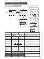
OPERATING INSTRUCTIONS
Turning Power On and Off
To turn the monitor power ON, press the main power
switch on the monitor main unit to ON, and then press
the SUB POWER button or the ON/OFF or ON button on
the remote control.
To turn the monitor power OFF, press the SUB POWER
button or the ON/OFF or OFF button on the remote
control, and then press the main power switch on the
monitor main unit to OFF.
During normal use, the main power switch is set in the ON
position, and the monitor can then be turned ON/OFF using the
SUB POWER button or the ON/OFF button on the remote control.
Indicating lamp
Indicating
lamp
Power status Operating
Off Off
When the main power switch is set
to OFF.
Lights red
Off
(standby)
When the main power switch is
ON, and the OFF button on the
remote control or the SUB POWER
button on the underside of the
front of the frame is OFF.
Lights green On
When the main power switch is
ON, and the ON button on the
remote control or the SUB POWER
button on the underside of the
front of the frame is ON.
Lights orange
Off
(standby)
When the main power switch is
ON, and the ON button on the
remote control or the SUB POWER
button on the underside of the
front of the frame is ON.
However, the state in POWER
SAVE mode
When the indicating lamp lights in orange or the message “NO
SYNC SIGNAL”, “POWER SAVE” or “OUT OF FREQUENCY” appears
on the screen, there is something unusual about the status of
reception. See “POWER SAVE MODE” or “Symptoms That
Seemingly Appear to be Failures.”
AUTO PinP SIZE
MUTE VOL
VOL
RECALL
RGB 1 RGB 2
ENTER
VIDEO 1 VIDEO 2
MENU RETURN
ID
ID SET
POWER OFF
button
POWER ON
button
POWER ON/OFF
button
SUB-POWER button
Main power switch
Indicating lamp
TIPS
• Avoid repeatedly turning the monitor on and off at short time
intervals. Failures might result from such operation.
• Turn off the main power switch before leaving the monitor out of
use for an extended period of time.
• If a power failure occurs while the main unit is running, it would
be powered on upon recovery from the failure. Turn off the unit
main power switch before leaving the main unit.

ENGLISH
AUTO PinP SIZE
MUTE VOL
VOL
RECALL
RGB 1 RGB 2
ENTER
VIDEO 1 VIDEO 2
MENU RETURN
ID
ID SET
OPERATING INSTRUCTIONS (continued)
Audio Mute
The audio volume can be temporarily lowered to the
mute volume level by pressing the MUTE button of the
remote control.
• When a button is pressed, the word MUTE (in pink) and
the volume adjustment status guide will be displayed.
• The volume setting can be lowered by pressing the VOL- button
while the audio is muted.
• The muting can be cancelled by pressing the VOL+ button while
the audio is muted.
• When audio is muted with the on-screen display
system, the volume setting can be adjusted.
When the MUTE button of the remote control is pressed
again, muting will be canceled, the volume display (blue)
will appear and sound will be output.
MUTE button
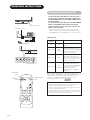
Input Switching
Input can be switched by pressing the RGB1, RGB2,
VIDEO 1 or VIDEO 2 buttons of the remote control.
Composite (S) and RGB VIDEO can be switched over
using VIDEO 1 button on the remote control unit.
Input can be switched in the sequence of RGB1
RGB2 VIDEO 1 VIDEO 2 by pressing the INPUT
SELECT button of the monitor.
When INPUT SELECT is pressed:
RGB1 (D-sub input)
RGB2 (D-sub input)
VIDEO1
(composite or S input)
VIDEO2 (component input)
• If the video unit is not installed, you cannot switch to VIDEO1 and
VIDEO2.
• When the same signal is input to RGB1 and RGB2, the phases may
be slightly misaligned. This is not a malfunction. In such case,
please change one refresh rate (Vertical frequency ) of the
apparatus to be used.
• When a button is pressed, the volume adjustment
status guide will be displayed.
• The volume will increase when the VOL+ (or
▲
) button is
pressed while the guide is being displayed.
• The volume will decrease when the VOL- (or
▼
) button is
pressed while the guide is being displayed.
• The volume can also be adjusted with the on-screen
display system.
Volume Adjustment
The volume can be adjusted by pressing the VOL+ and
VOL- buttons of the remote control (or the
▲
and
▼
volume buttons of the monitor unit) while the on-screen
display system is not being displayed.
VOLUME 15
Volume setting value
Adjustment status guide display
VOLUME
UP/DOWN buttons
INPUT SELECT button
VOLUME buttons
RGB/VIDEO
buttons
VOLUME 15
Volume setting value
Adjustment status guide display
(The display color will change to pink.)
*(When RGB VIDEO Select)
RGB1 (D-sub input)
RGB2 (D-sub input)
VIDEO1
(RGB VIDEO)
Composite (S) RGB VIDEO

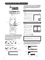
Size Switching
Each time the SIZE button of the remote control or the
monitor is pressed, the screen display size (or display
area) will change in sequence and the status will be
displayed at the bottom of the screen.
• During RGB signal input
• Some types of signals may not be able to switch as desired.
* VGA and W-VGA only
• During VIDEO signal input
(when the optional video unit is attached)
• Depending on the type of signal, in some cases it may not be
possible to switch the size, or switching to some sizes may not be
possible.
<<
FULL
>>
NORMAL FULL ZOOM1
REAL ZOOM3 ZOOM2
4:3 PANORAMA MOVIE1
FULL MOVIE2
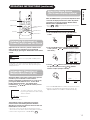
Displaying Two Screens
If the PinP button on the remote control is pressed when
the optional video unit is installed, two screens will
display.
Activating the P-in-P mode from the RGB input screen
Pressing the PinP button one time will display two
screens.
The speaker icon can be shifted left and right by pressing the
and SELECT buttons; the audio
of the video will be output from the
side on which the speaker icon is
located.
The sub-screen can be selected
with the VIDEO1 and VIDEO2
buttons from the status shown in the
diagram to the right.
Pressing the PinP button again will
cancel the two screen display.
V1: Displays the VIDEO input signal of the sub-screen.
Activating the P-in-P mode from the video input screen
Pressing the PinP button one time will display two
screens.
• The speaker icon can be shifted
left and right by pressing the and
SELECT buttons; the audio of
the video will be output from the
side on which the speaker icon is
located.
• Pressing the PinP button again will
increase the size of the screen.
• Pressing the PinP button once
again will cancel the two screen
display.
•
When VIDEO1 set it to RGB Video, it is not completed in P in P mode.
Refer to two screen table
PinP button
SIZE button
AUTO PinP SIZE
MUTE VOL
VOL
RECALL
RGB 1 RGB 2
ENTER
VIDEO 1 VIDEO 2
MENU RETURN
ID
ID SET
SIZE button
RECALL button
Input Signal Screen Display
RGB1
[RGB]
H : 46.5kHz V : 60Hz
Input terminal name
The input signal status can be displayed on the screen
by pressing the RECALL button of the remote control.
The display will go out in approximately 3 seconds.
Input horizontal
frequency
Input vertical
frequency
VIDEO2
[COMPONENT]
VIDEO
RGB
R1 V1
(Sub-
screen)
V1 V2
OPERATING INSTRUCTIONS (continued)
TIPS
Even if the input of the horizontal / vertical synchronizing signal
(or video signal) stops in the two screen display, the mode will
not change to power save mode.
Please be careful since image retention will occur if display is left
in a two screen display state for a long period of time.
RECALL button
*

ENGLISH
AUTO PinP SIZE
MUTE VOL
VOL
RECALL
RGB 1 RGB 2
ENTER
VIDEO 1 VIDEO 2
MENU RETURN
ID
ID SET
ID SET button
ID button
AUTO button
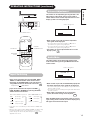
Using the Menu Screen
(On-screen display system)
When the MENU button is pressed, the adjustment menu
screen will be displayed; from there, video adjustment
and setting is possible by using the SELECT button,
ADJUST button and ENTER button.
• Refer to - concerning the adjustment items and the
settings.
Example: Selecting the Picture screen
1. Press the MENU button to display the Main Menu
screen.
2. Press the ENTER button to display the Picture Menu
screen. (Use the and SELECT buttons to select
other items.)
3. Use the and SELECT buttons to select the item to
be adjusted and then use the and ADJUST
buttons to adjust (example: COLOR).
• Press the RETURN button to return to the previous screen.
• If there is no operation for a period of one minute, the
Adjustment Menu screen will be closed automatically.
MENU
MAIN MENU
PICTURE
SOUND
DISPLAY
FUNCTION
OTHER
SEL. ENT ENT. RTN END
ENTER
PICTURE MENU 1/2
OPERATE MODE : NORMAL
CONTRAST : 127
BRIGHTNESS : 0
COLOR : 0
TINT : 0
ENHANCER : LOW
FILTER : OFF
RESET
SEL. ENT ENT. RTN BACK
OPERATING INSTRUCTIONS (continued)
ADJ RTN BACK
COLOR 0
Independent Operation of
Multiple Monitors (ID No)
Setting the ID No. of the remote control allows separate
control of up to a maximum of seven monitors.
Remote control ID No. 2 (initially ID no. 1) can be set by
pressing the ID SET button for 2 sec. or more while
holding down the ID button. The number will be
incremented (2 6 7 1 2) when this button pressed
continuously.
The ID remote control is operated by pressing the
various buttons while holding down the ID button;
Operation is possible only when the remote control and
monitor ID nos. are the same.
• The remote control can be operated normally by pressing the
various remote control buttons without holding down the ID button.
• Set the monitor using the ID No. of OTHER MENU.
Automatic Adjustment of
Screen Position and the Clock
Adjustment of the screen to a position suitable for the
video and the clock adjustment can be performed
automatically by pressing the AUTO button of the remote
control.
* Depending on the signal, satisfactory adjustment may not be
possible in some cases. In such case, adjust by referring to the
Display Menu item.
SET. ID:1
R/C.
ID:1
Monitor ID no.
Remote control ID no.
The remote control ID no. can be checked
by pressing the ID SET button while holding
down the ID button.
Perform this adjustment for each input (RGB1 or RGB2) and for
each signal.
CAUTIONS
MENU button
ENTER button
SELECT/ADJUST
buttons

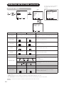
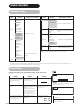
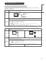
PICTURE MENU
Selected characters Setup hint
OPERATE MODE
NORMAL LIFE EXTEN.1 LIFE EXTEN.2
By controlling the brightness of a screen, power consumption can be
reduced or degradation of a panel can be mitigated.
The order of
effectiveness in reducing power consumption and reducing panel
degradation is LIFE EXTEN.2 > LIFE EXTEN.1 > NORMAL.
CONTRAST
Narrows the gap between
brightness and darkness.
Broadens the gap between
brightness and darkness.
Adjust for maximum visibility to suit the ambient brightness.
Cannot be used when
LIFE
EXTEN1, 2 are selected.
BRIGHTNESS
Black is subdued for
increasedoverall darkness.
Black is set off for increased
overall brightness.
Adjust to prevent black from spreading across the screen.
COLOR
Lightens colors. Darkens colors.
Adjust for desired density, somewhat for lighter colors for a natural
look.
TINT
Enhances red and weakens
green.
Enhances green and
weakens red.
Adjust for a nice looking skin color.
ENHANCER
OFF LOW MID HIGH
Sets the clarity of small details to the desired level.
FILTER
Only displayed for RGB signals. Turn ON when concerned about
screen flicker.
RESET
The original factory settings can be restored by pressing the ENTER
button.
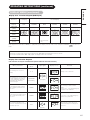
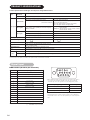
MODE
Set to MOVIE when viewing moving images on a personal computer.
GAMMA
2.2 2.8
Normally set to 2.2.
VIDEO LEVEL
0.7 1.0
Normally set to 0.7 V. If white is found to spread across the screen,
set to 1.0 V.
COLOR TEMP.
COOL NORM WARM USER
Normally set to COOL.
R-GAIN
Red is weakened. Red is strengthened.
Sets the color adjustment selected by the user with COLOR TEMP..
USER mode takes effect automatically when an attempt is made to
set a gain.
G-GAIN
Green is weakened. Green is strengthened.
B-GAIN
Blue is weakened. Blue is strengthened.
(This function can only be used when the optional
video unit has been inserted.)
OPERATING INSTRUCTIONS (continued)
MAIN MENU
PICTURE
SOUND
DISPLAY
FUNCTION
OTHER
SEL. ENT ENT. RTN END
PICTURE MENU 1/3
OPERATE MODE : NORMAL
CONTRAST : 127
BRIGHTNESS
: 0
COLOR
: 0
TINT
: 0
SHARPNESS
: 0
RESET
SEL. ENT ENT. RTN BACK
PICTURE MENU 1/2
OPERATE MODE : NORMAL
CONTRAST : 127
BRIGHTNESS : 0
COLOR : 0
TINT : 0
ENHANCER : LOW
FILTER : OFF
RESET
SEL. ENT ENT. RTN BACK
VIDEO
RGB
PICTURE MENU 2/2
MODE : PC
GAMMA : 2.2
VIDEO LEVEL : 0.7V
COLOR TEMP. : COOL
R-GAIN : 255
G-GAIN : 255
B-GAIN : 255
SEL. ADJ. RTN BACK
PICTURE MENU 3/3
3D COMB : ON
FILM MODE : ON
GAMMA : 2.2
LINE INTP. : OFF
COLOR TEMP. : COOL
R-GAIN : 255
G-GAIN : 255
B-GAIN : 255
SEL. ADJ. RTN BACK
ENTER
MENU
PICTURE MENU 2/3
VIDEO PICTURE : NORMAL
CONTRAST MODE : DYNAMIC
BLACK STRETCH
: OFF
LTI : LOW
CTI : LOW
YNR : LOW
CNR : LOW
RESET
SEL. ADJ. RTN BACK

ENGLISH
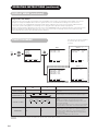
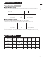
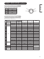
PICTURE MENU (continued)
Selected characters Setup hint
SHARPNESS
Picture is soft Picture is sharp
In general, position is in the center and shift to the minus (-) side
when a softer effect is desired.
VIDEO PICTURE
NORMAL SOFT
Use SOFT when DVD, video and other images become harsh or picture
noises on the screen is evident. Use NORMAL
as standard.
CONTRAST MODE
DYNAMIC LINEAR AUTO
DYNAMIC:Emphasizes the differences between video shadings to
improve the feeling of contrast.
LINEAR : The gradation of an image is reproduced as faithfully as
possible.
AUTO:Detects image brightness and automatically adjusts for
natural brightness.
BLACK STRETCH
OFF LOW MID HIGH
Adjusts the black level compensation.
LTI
Adjusts the sharpness of the brightness signal.
CTI
Adjusts the sharpness of the color signal.
YNR
LOW HIGH OFF
Performs brightness signal noise reduction. Turn up to reduce noise.
CNR
Performs color signal noise reduction. Turn up to reduce noise.
3D COMB
ON OFF
Set to OFF when video and other images appear unnatural. Set to
ON for normal use. Only an NTSC composite signal input is effective.
It cannot choose at the time of a component signal (VIDEO 2).
FILM MODE
OFF ON
ON:Automatically detects the movie film material and faithfully
reproduces the original film image. Set to ON normally.
OFF:Set to OFF when switching between images does not appear
natural.
LINE INTP.
OFF ON Set to ON when using 3-D video disks. Set to OFF normally.
This function can only be used when the optional video unit has been inserted.
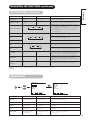
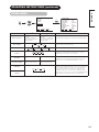
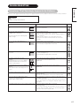
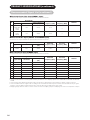
Selected characters Setup hint
VOLUME
Turns down the volume. Turns up the volume. Adjust for the desired sound volume.
BALANCE
Suppresses right-side sound. Suppresses left-side sound. Adjust to taste.
TREBLE
Suppresses treble. Enhances treble. Adjust to taste.
BASS
Suppresses bass. Enhances bass. Adjust to taste.
MUTE LEVEL
Turns down the sound
volume.Minimum 0.
Turns up the sound
volume.Maximum pre-mute
sound volume.
Varies the sound volume when the MUTE
button is pressed.
MAIN MENU
PICTURE
SOUND
DISPLAY
FUNCTION
OTHER
SEL. ENT ENT. RTN END
SOUND MENU
VOLUME : 20
BALANCE : 0
TREBLE : 0
BASS : 0
MUTE LEVEL : 0
SEL. ADJ. RTN BACK
ENTER
MENU
SOUND MENU
OPERATING INSTRUCTIONS (continued)
La pagina si sta caricando...
La pagina si sta caricando...
La pagina si sta caricando...
La pagina si sta caricando...
La pagina si sta caricando...
La pagina si sta caricando...
La pagina si sta caricando...
La pagina si sta caricando...
La pagina si sta caricando...
La pagina si sta caricando...
La pagina si sta caricando...
La pagina si sta caricando...
La pagina si sta caricando...
La pagina si sta caricando...
-
 1
1
-
 2
2
-
 3
3
-
 4
4
-
 5
5
-
 6
6
-
 7
7
-
 8
8
-
 9
9
-
 10
10
-
 11
11
-
 12
12
-
 13
13
-
 14
14
-
 15
15
-
 16
16
-
 17
17
-
 18
18
-
 19
19
-
 20
20
-
 21
21
-
 22
22
-
 23
23
-
 24
24
-
 25
25
-
 26
26
-
 27
27
-
 28
28
-
 29
29
-
 30
30
-
 31
31
-
 32
32
-
 33
33
-
 34
34


Hitachi 42PMA400E Manuale utente
- Categoria
- TV al plasma
- Tipo
- Manuale utente
- Questo manuale è adatto anche per
in altre lingue
- English: Hitachi 42PMA400E User manual
Documenti correlati
Altri documenti
-
Yamaha PDM-1 Manuale del proprietario
-
NEC PlasmaSync® 42XP10 Manuale del proprietario
-
-
-
Pioneer Flat Panel Television PDP-42MVE1 Manuale utente
-
Pioneer PLASMA DISPLAY Manuale utente
-
Panasonic TH-42PH9ES Scheda dati
-
NEC PlasmaSync® 42XM5 Manuale del proprietario
-
NEC Flat Panel Television 50XM6 PX-50XM6G and 60XM5 PX-60XM5G Manuale utente
-
Electrolux EMS2388 Manuale utente