Magnum Energy ME Series Manuale del proprietario
- Categoria
- Adattatori di alimentazione
- Tipo
- Manuale del proprietario

ME Series
Modifi ed Sine Wave
Inverter/Chargers
Owner’s Manual

© 2010 Magnum Energy, Inc.
Page i
Disclaimer of Liability
The use of this manual and the conditions or methods of installation, operation, use, and
maintenance of the ME Series Inverter/Charger is beyond the control of Magnum Energy Inc.
Therefore, this company assumes no responsibility and expressly disclaims any liability for loss,
damage, or expense whether direct, indirect, consequential, or incidental that may arise out of or
be in anyway connected with such installation, operation, use, or maintenance.
Due to continuous improvements and product updates, the images shown in this manual may not
exactly match the unit purchased.
Restrictions on Use
The ME Series Inverter/Charger may only be used in life-support devices or systems with the express
written approval of Magnum Energy. Failure of the ME Series Inverter/Charger can reasonably
be expected to cause the failure of that life-support device or system, or to affect the safety or
effectiveness of that device or system. If the ME Series Inverter/Charger fails, it is reasonable to
assume that the health of the user or other persons may be endangered.
Copyright Notice
Copyright © 2004, 2010 by Magnum Energy, Inc. All rights reserved. Permission to copy,
distribute, and/or modify this document is prohibited without express written permission by Mag-
num Energy, Inc.
Contact Information
Magnum Energy, Inc.
2211 West Casino Rd.
Everett, WA 98204
Phone: 425-353-8833
Fax: 425-353-8390
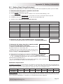
Record the unit’s model and serial number in case you need to provide this
information in the future. It is much easier to record this information now,
instead of trying to gather it after the unit has been installed.
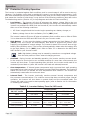
Model: Serial Number:
ME2000 (-15B/-20B) N1
ME2012 (-15B/-20B) B1
ME2512 C1
ME3112 D1
Magnum Energy® is a registered trademark of Magnum Energy, Inc.

Page ii
© 2010 Magnum Energy, Inc.
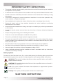
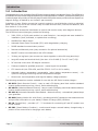
IMPORTANT SAFETY INSTRUCTIONS
This manual contains important safety instructions that must be followed during the installation
and operation of this product.
All electrical work must be performed in accordance with local, state and federal electrical codes.
Read all instructions and safety information contained in this manual before installing or using
this product.
This product is designed for indoor/compartment installation. It must not be exposed to rain,
snow, moisture, or liquids of any type.
Use insulated tools to reduce the chance of electrical shock or accidental short circuits.
Remove all jewelry such as rings, watches, bracelets, etc., when installing or performing
maintenance on the inverter.
Always disconnect the batteries or energy source prior to installing or performing maintenance
on the inverter.
Live power may be present at more than one point since an inverter utilizes both batteries
and AC.
Always verify proper wiring prior to starting the inverter.
There are no user-serviceable parts contained in this product.
This unit is provided with integral protection against overloads.
The input and output AC and DC circuits are isolated from the inverter chassis. The inverter
system grounding is the responsibility of the installer in accordance with the NEC/CEC, ABYC,
RVIA, and local codes.
Both AC and DC overcurrent protection must be provided as part of the installation.
Use Class 1 wiring methods for fi eld-wiring connections to terminals of a Class 2 circuit.
Use only copper wires with a minimum temperature rating of 90°C.
Listed or labeled equipment shall be installed and used in accordance with any instructions
included in the listing or labeling.
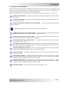
Safety Symbols
To reduce the risk of electrical shock, fi re, or other safety hazard, the following safety symbols have
been placed throughout this manual to indicate dangerous and important safety instructions.
WARNING: This symbol indicates that failure to take a specifi ed action could result in
physical harm to the user.
CAUTION: This symbol indicates that failure to take a specifi ed action could result in
damage to the equipment.
Info: This symbol indicates information that emphasizes or supplements important
points of the main text.
Remedy: This symbol provides possible solutions for related issues.
SAVE THESE INSTRUCTIONS
•
•
•
•
•
•
•
•
•
•
•
•
•
•
•
•

© 2010 Magnum Energy, Inc.
Page iii
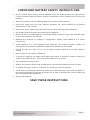
IMPORTANT BATTERY SAFETY INSTRUCTIONS
Be very careful when working around batteries, they can produce extremely high currents
if short-circuited. Read the battery supplier’s precautions before installing the inverter and
batteries.
Wear eye protection such as safety glasses when working with batteries.
Remove all jewelry such as rings, watches, bracelets, etc., when installing or performing
maintenance on the inverter.
Never work alone. Always have someone near you when working around batteries.
Use proper lifting techniques when working with batteries.
Never use old or untested batteries. Check each battery’s label for age, type, and date code
to ensure all batteries are identical.
Batteries are sensitive to changes in temperature. Always install batteries in a stable
environment.
Install batteries in a well ventilated area. Batteries can produce explosive gases. For
compartment or enclosure installations, always vent batteries to the outside.
Provide at least one inch (2.5 cm) of air space between batteries to provide optimum
cooling.
Never smoke in the vicinity of batteries.
To prevent a spark at the battery and reduce the chance of explosion, always connect the
cables to the batteries fi rst. Then connect the cables to the inverter.
Use insulated tools at all times.
Always verify proper polarity and voltage before connecting the batteries to the inverter.
To reduce the chance of fi re or explosion, do not short-circuit the batteries.
In the event of accidental exposure to battery acid, wash thoroughly with soap and water. In
the event of exposure to the eyes, fl ood them for at least 15 minutes with running water and
seek immediate medical attention.
Recycle old batteries.
SAVE THESE INSTRUCTIONS
•
•
•
•
•
•
•
•
•
•
•
•
•
•
•
•

Page iv
© 2010 Magnum Energy, Inc.
Table of Contents
1.0 Introduction ..................................................................................1
1.1 Features and Benefi ts ................................................................................. 2
1.2 How an Inverter/Charger Works ................................................................... 5
1.3 What Appliances will run from a Modifi ed Sine Wave Inverter ........................... 5
1.4 Appliances and Run Time ............................................................................ 5
2.0 Installation ...................................................................................7
2.1 Pre-Installation .......................................................................................... 7
2.2 Mounting the Inverter ...............................................................................10
2.3 Wiring the Inverter - General Requirements .................................................12
2.4 DC Wiring ................................................................................................13
2.5 AC Wiring ................................................................................................19
2.6 Grounding Inverters ..................................................................................33
2.7 Inverter Notifi cation Requirements ..............................................................36
2.8 Final Inspection ........................................................................................37
2.9 Functional Test .........................................................................................37
3.0 Operation ....................................................................................39
3.1 Inverter Mode ..........................................................................................39
3.2 Standby Mode ..........................................................................................40
3.3 Battery Charging ......................................................................................40
3.4 Transfer Time ...........................................................................................42
3.5 Battery Temperature Sensor Operation ........................................................42
3.6 Protection Circuitry Operation .....................................................................43
3.7 Inverter Startup .......................................................................................44
3.8 Factory Default Values ...............................................................................45
4.0 Maintenance and Troubleshooting ...............................................46
4.1 Recommended Inverter and Battery Care .....................................................46
4.2 Storage for Mobile Installations...................................................................46
4.3 Troubleshooting ........................................................................................47
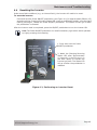
4.4 Resetting the Inverter ...............................................................................48
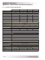
Appendix A - Specifi cations and Optional Equipment ...........................49
A-1 Inverter/Charger Specifi cations ..................................................................49
A-2 Optional Equipment and Accessories............................................................50
Appendix B - Battery Information .......................................................51
B-1 Battery Location .......................................................................................51
B-2 Battery Types ...........................................................................................51
B-3 Battery Temperature .................................................................................51
B-4 Battery Bank Sizing ..................................................................................51
B-5 Battery Bank Sizing Worksheet ...................................................................52
B-6 Battery Wiring Confi gurations .....................................................................53
Limited Warranty ................................................................................55
How to Receive Repair Service ............................................................55

© 2010 Magnum Energy, Inc.
Page v
List of Figures
Figure 1-1, Power Switch, Status LED, and Accessory Connection Ports ................................................3
Figure 1-2, Electrical Connection Points ...........................................................................................3
Figure 1-3, Left Side Features ........................................................................................................4
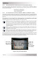
Figure 2-1, Simplifi ed Installation Diagram for Permanent Installations ................................................8
Figure 2-2, Approved Mounting Positions ....................................................................................... 10
Figure 2-3, ME Series Dimensions and Side Reference ..................................................................... 11
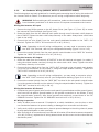
Figure 2-4, DC and Battery Temperature Sensor Wiring ................................................................... 14
Figure 2-5, Battery Hardware Installation ......................................................................................16
Figure 2-6, Inverter DC Hardware Installation ................................................................................ 16
Figure 2-7, Battery Temperature Sensor ........................................................................................ 17
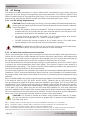
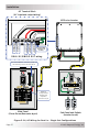
Figure 2-8, ME Series Inverter/Charger - AC Wiring ........................................................................ 20
Figure 2-9, ME Series Inverter/Charger - AC Wiring (Access Cover) .................................................. 20
Figure 2-10, AC Terminal Block ..................................................................................................... 21
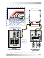
Figure 2-11, AC Wiring for Single In - Single Out (30 A) Confi gurations ............................................. 24
Figure 2-12, AC Wiring for Single In - Single Out (60 A) Confi gurations ............................................. 25
Figure 2-13, AC Wiring for Single In - Dual Out Confi gurations ......................................................... 26
Figure 2-14, AC Wiring for Dual In - Single Out Confi gurations ......................................................... 27
Figure 2-15, AC Wiring for Dual In - Dual Out Confi gurations ............................................................ 28
Figure 2-16, AC Wiring for Single In - Single Out (ME2000 models) Confi gurations .............................. 31
Figure
2-17, AC Wiring for Single In - Dual Out (ME2000-15B/-20B models) Confi gurations ................. 32
Figure 2-18, Neutral-to-Ground Connection (Inverter Mode) ............................................................. 35
Figure 2-19, Neutral-to-Ground Connection (Standby Mode) ............................................................. 35
Figure 2-20, Large Ground Wire Connected to ME Series .................................................................. 36
Figure 2-21, Warning Label .......................................................................................................... 36
Figure 2-22, AC Voltage Checks .................................................................................................... 38
Figure 2-23, AC Voltage Checks (ME2000 model) ............................................................................ 38
Figure 2-24, AC Voltage Checks (ME2000-15B/-20B models) ............................................................ 38
Figure 3-1, Power Flow - Inverter Mode .........................................................................................39
Figure 3-2, Power Flow - Standby Mode ......................................................................................... 40
Figure 3-3, Automatic 4-Stage Charging Graph ............................................................................... 41
Figure 3-4, BTS Temperature to Charge Voltage Change .................................................................. 42
Figure 3-5, Power Switch and Status Indicator ................................................................................ 44
Figure 4-1, Performing an Inverter Reset .......................................................................................48
Figure B-1, Series Battery Wiring .................................................................................................. 53
Figure B-2, Parallel Battery Wiring ................................................................................................ 53
Figure B-3, Series-Parallel Battery Wiring....................................................................................... 53
Figure B-4, Battery Bank Wiring Examples (12-volt) ........................................................................ 54
List of Tables
Table 1-1, Typical Appliance Power Consumption ...............................................................................6
Table 2-1, Recommended DC Wire/Overcurrent Device for Rated Use ................................................ 15
Table 2-2, DC Wire Size For Increased Distance .............................................................................. 16
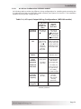
Table 2-3, AC Input/Output Wiring Confi gurations (ME2012, ME2512, and ME3112 models) .................. 23
Table 2-4, AC Input/Output Wiring Confi gurations (ME2000 models) .................................................. 30
Table 2-5, Equipment Grounding Conductor Sizing .......................................................................... 33
Table 3-1, Inverter Battery Turn On/Off Levels ................................................................................ 43
Table 3-2, Inverter/Charger Default Values .................................................................................... 45
Table 4-1, Basic Troubleshooting ................................................................................................... 47

© 2010 Magnum Energy, IncPage 1
Introduction
1.0 Introduction
Congratulations on your purchase of the ME Series inverter/charger from Magnum Energy. The ME Series is
a modifi ed sine wave inverter designed especially for mobile applications. Powerful, yet simple to operate, this
inverter/charger will provide you with the years of trouble-free performance you have come to expect from
Magnum Energy, all backed by our limited 3 year warranty.
Installation is easy. Simply connect the inverter’s output to your distribution circuits or electrical
panel, connect your AC to the inverter’s easy-to-reach terminal block, connect the batteries, and
then switch it on for power.
Use the optional accessories listed below to control and monitor many other Magnum devices.
The ME Series inverter/chargers provide the following:
2000, 2500, or 3100 watt models in a small footprint – less weight and area needed for
installation (shelf, bulkhead, or upside-down mounting)
Modifi ed Sine Wave output
Automatic Power Factor Corrected (PFC) multi-stage battery charging
RS485 standard communication protocol
Remote and Network ports (easy connection for optional accessories)
ON/OFF inverter-mounted switch with LED indicator
30 Amp per leg/input (can connect two inputs together to allow 60 Amp pass-thru)*
Large AC access and terminal block [wire size: 10 to 6 AWG (5.3 to 13.3 mm
2
) CU]*
DC terminal covers with 360 degree connection
Field-serviceable for qualifi ed personnel – tested repair kits available
ETL listed to UL/cUL STDs 458, and CSA STD 22.2 107.01-01 for safety
Automatic battery temperature compensation (using battery temperature sensor) – for
optimum charging even during extreme temperature changes
Overcurrent, over-temperature, and high/low battery voltage protection
The following accessories are also available for use with the ME Series inverter/charger:
ME-RC50 (Basic Remote Control) - easy to read LCD display panel that enables standard
inverter and accessories set up, control, and troubleshooting.
ME-ARC50 (Advanced Remote Control) - easy to read LCD display panel that enables advance
inverter and accessories set up, control, and troubleshooting.
ME-AGS-N (Automatic Generator Start Module - Network version) - automatically starts/stops
your generator.
ME-BMK (Battery Monitor Kit - with Shunt) - provides precise DC voltage/current measurements
and provides information on your battery’s State of Charge (SOC) condition.
ME-CB (Conduit Box) - provides 1/2” - 2” knockouts for connecting AC and DC conduit runs
to the inverter.
ME-SBC (Smart Battery Combiner) - monitors and keeps a second battery charged using a
portion of the current that is charging a main battery.
•
•
•
•
•
•
•
•
•
•
•
•
•
•
•
•
•
•
•
* - Not applicable to the ME2000 models.

Page 2
© 2010 Magnum Energy, Inc.
Introduction
1.1 Features and Benefi ts
The ME Series inverter/charger is designed to allow easy access to wiring, circuit breakers, and
controls. Its die cast baseplate with one-piece aluminum cover ensures maximum durability with
minimum weight, as well as cooler more effi cient operation.
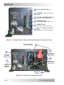
The front of the ME Series is equipped with the following features (see Figures 1-1 and 1-2):
1
Power ON/OFF Switch - a momentary pushbutton switch that alternately turns the inverter
On or Off.
2
Status LED Indicator - this green LED illuminates to provide information on the inverter
or charger operation.
3
Stack/Accessories Connection Port (red label) - a RJ11 port that accepts optional
accessories.
Info: The stacking feature is NOT available with the ME Series.
4
Network Connection Port (green label) - a RJ11 port that accepts optional network
capable accessories (e.g., Auto Gen Start or Battery Monitor).
5
Remote Connection Port (blue label) - a RJ11 port that allows the optional remote
controls (ME-RC50 or ME-ARC50) to be connected.
6
BTS Connection Port (yellow label) - RJ11 port that accepts the remote Battery
Temperature Sensor (BTS).
7
DC Equipment Ground Terminal - this connection is used to tie the exposed chassis of
the inverter to the DC grounding system. This terminal accepts CU/AL conductors from
#14 to #2 AWG (2.1 to 33.6 mm
2
).
8
AC Input/Output Connections - two 3/4” knockouts provided with cable-clamp strain
reliefs to allow and hold the AC input and output fi eld wiring.
9
Intake Air Vents - ventilation openings to pull in air to help keep the inverter cool for
peak performance.
10
Positive DC Terminal - provides 360 degree connection point for the positive (+) cable
from the battery bank; provided with a Kep or Flange nut on a 5/16-18 bolt (5/8” usable
length) to hold the battery cable to the DC terminal.
11
Negative DC Terminal - provides 360 degree connection point for the negative (-) cable
from the battery bank; provided with a Kep or Flange nut on a 5/16-18 bolt (5/8” usable
length) to hold the battery cable to the DC terminal.
12 Mounting Flange - used to secure the inverter to a shelf or wall.

© 2010 Magnum Energy, IncPage 3
Introduction
Figure 1-1, Power Switch, Status LED, and Accessory Connection Ports
Figure 1-2, Electrical Connection Points
POWER ON/OFF SWITCH
STATUS (CHARGING/INVERTING)
LED
STACK/ACCESSORIES PORT
(RED LABEL - RJ11 CONNECTION)
NETWORK PORT
(GREEN LABEL - RJ11 CONNECTION)
REMOTE PORT
(BLUE LABEL - RJ11 CONNECTION)
BATTERY TEMPERATURE SENSOR
P
ORT
(YELLOW LABEL - RJ11 CONNECTION)
INTAKE AIR VENTS
(AND ON RIGHT SIDE)
AC INPUT/
O
UTPUT
CONNECTIONS
DC
EQUIPMENT
GROUND
TERMINAL
POSITIVE (+)
DC TERMINAL
(UNDER COVER)
NEGATIVE (-)
DC
TERMINAL
(UNDER COVER)
6
4
3
2
1
11
10
12
7
8
9
5
MOUNTING
FLANGE

Page 4
© 2010 Magnum Energy, Inc.
Introduction
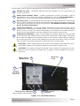
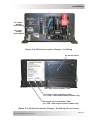
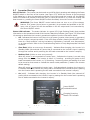
The left side of the ME Series is equipped with the following features (see Figure 1-3):
13
Exhaust Air Vent - ventilation openings that allow heated air to be removed by the
internal cooling fan.
14
Model/Serial Number Label - includes model/serial number information, date of
manufacture, and inverter and charger specifi cations. See the ME Specifi cations in
Appendix A for more information and the different models that are available.
15
AC Access Cover - provides access to the internal AC wiring terminal block. This terminal
block is used to hardwire all inverter AC input and output wiring connections. Remove the
two screws to access the AC wiring terminal block. The ME2000 models do not have
the AC wiring terminal block.
16
Input Circuit Breaker - this circuit breaker protects the unit’s internal charger wiring
and pass-thru relay while in Standby Mode. This circuit breaker will pop out when it
opens. Press in to reset. This input circuit breaker is not branch-circuit rated, therefore,
branch-circuit rated breakers must be installed in the inverter’s input wiring.
Output Circuit Breakers - these circuit breakers are branch-rated, but only provided
on the ME2000-15B, ME2000-20B, ME2012-15B, and ME2012-20B models. They allow
the inverter AC loads to be connected directly to the inverter’s output without requiring
an inverter sub-panel. These circuit breakers pop out when they open. Press in to reset.
They can also be manually pulled out to disconnect the inverter’s loads.
CAUTION: Inverter models without the output circuit breakers (CB1 and CB2) must
have branch-rated circuit breakers installed in the inverter’s output wiring.
CAUTION: The inverter’s internal AC transfer relay is rated for 30 amps per leg. The
pass-thru current must be no greater than 30 amps per leg or damage to the relays
may occur.
17
Figure 1-3, Left Side Features
13
EXHAUST
AIR VENTS
(BACK SIDE)
MODEL/SERIAL
NUMBER LABEL
14
AC ACCESS
COVER
OUTPUT CIRCUIT BREAKERS
(ONLY AVAILABLE ON CERTAIN MODELS)
INPUT CIRCUIT
B
REAKER
16
15
17

© 2010 Magnum Energy, IncPage 5
Introduction
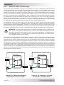
1.2 How an Inverter/Charger Works
An inverter takes direct current (DC) from your batteries and turns it into alternating current (AC).
It also takes alternating current (when connected to an onboard generator or to shore power) and
transforms it into direct current to charge your batteries. These two modes of operation associated
with this inverter/charger are referred to in this document as:
Inverter Mode:
When the inverter is properly connected to batteries and turned on, the direct current
(DC) from the batteries is transformed into a modifi ed sine wave alternating current (AC).
This AC is similar to the voltage provided by a utility for your home, and is used to power
the electrical appliances (i.e., AC loads) connected to the inverter’s output.
Standby Mode:
When an external source of AC power (e.g., shore power or onboard generator) is connected
and qualifi ed on the inverter’s AC input, it operates in the Standby Mode. In the Standby
Mode, the unit operates as a Battery Charger to convert the incoming AC power into DC
power to recharge the batteries; and at the same time, automatically closes an internal AC
Transfer Relay to pass the incoming AC power directly to the inverter’s output to continue
powering the connected electrical appliances.
1.3 What Appliances will run from a Modifi ed Sine Wave Inverter
Today’s inverters come in two basic output waveforms: modifi ed sine wave (which is actually a
modifi ed square wave) and pure sine wave. Modifi ed sine wave inverters approximate a pure sine
waveform and will run most appliances and electronics without any problems. These inverters are
less expensive, and therefore, offer a viable alternative to more expensive pure sine inverters.
The output of a modifi ed sine wave inverter will run most electronic and household items, including
but not limited to: TV, VCR, satellite dish receiver, computers, and printers. Some devices such as
rechargeable power supplies for phones, drills, and other like items may not run, and could even
be at risk for damage from modifi ed sine wave inverters.
1.4 Appliances and Run Time
The ME Series inverter/charger can power a wide range of household appliances including small
motors, hair dryers, clocks, and other electrical devices. As with any appliance using batteries
for power, there is a certain length of time that it can run – this is called “run time.” Actual run
time depends on several variables, including: the size and type of appliance, the type of batteries
installed in your application, as well as the battery’s capacity and age. Other factors such as the
battery’s state of charge (SOC) and temperature can also affect the length of time your appliances
can run.
Appliances such as TVs, VCRs, stereos, computers, and lights can all be successfully powered
by your inverter. Depending on your inverter capacity, electrical appliances that use larger loads
such as coffee pots and hair dryers can be used for short durations. However, loads that are
used for longer periods (stoves, water heaters, etc.) can quickly drain your batteries and are not
recommended for inverter applications.
All electrical appliances are rated by the amount of power they consume (See Table 1-1). The rating
is printed on the product’s nameplate label, usually located on its chassis near the AC power cord.
Even though it is diffi cult to calculate exactly how long an inverter will run a particular appliance,
the best advice is trial and error. Your ME Series inverter has a built-in safeguard that automatically
protects your batteries from over-discharge.
•
•

Page 6
© 2010 Magnum Energy, Inc.
Introduction
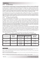
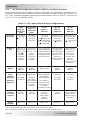
Info: For optimum performance, a minimum battery bank of 200 AH is recommended
for moderate loads (<1000W) and greater than 400 AH for heavy loads (≥1000W).
Table 1-1, Typical Appliance Power Consumption
Device Load Device Load
Blender 400W Coffee Maker 1200W
Computer 300W Color TV 150W
Drill 500W Hair Dryer 1000W
Hot Plate 1800W Iron 1000W
Light (Flo) 10W Light (Inc) 100W
Microwave 1000W Refrigerator 500W

© 2010 Magnum Energy, IncPage 7
Installation
2.0 Installation
WARNING: Installations should be performed by qualifi ed personnel, such as a licensed
or certifi ed electrician. It is the installer’s responsibility to determine which safety
codes apply and to ensure that all applicable installation requirements are followed.
Applicable installation codes vary depending on the specifi c location and application of
the installation.
CAUTION: Review the “Important Product Safety Information” on page ii, and the
“Important Battery Safety Instructions” on page iii before any installation.
CAUTION: The inverter is heavy. Use proper lifting techniques during installation to
prevent personal injury.
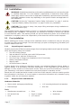
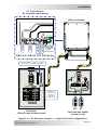
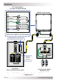
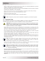
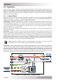
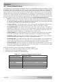
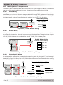
The simplifi ed system diagram shown in Figure 2-1 should be reviewed to assist you in planning
and designing your installation. This drawing is not intended to override or restrict any national
or local electrical codes. This drawing should not be the determining factor as to whether the
installation is compliant, that is the responsibility of the electrician and the onsite inspector.
2.1 Pre-Installation
Before installing the inverter, read the entire installation section to determine how you are going
to install your ME inverter/charger. The more thorough you plan in the beginning, the better your
inverter needs will be met.
2.1.1 Unpacking and Inspection
Carefully remove the ME Series inverter/charger from its shipping container and inspect all contents.
Verify the following items are included:
The ME Inverter/Charger
Red and black DC terminal covers with Phillips screws
AC access cover with two Phillips screws
Two 5/16” Kep or Flange nuts (installed on the DC terminals)
Battery Temperature Sensor
Warning label
ME Series Owner’s Manual
If items appear to be missing or damaged, contact your authorized Magnum Energy dealer or
Magnum Energy. If at all possible, keep your shipping box. It will help protect your inverter from
damage if it ever needs to be returned for service. Save your proof-of-purchase as a record of
your ownership; it will also be needed if the unit should require in-warranty service.
Record the unit’s model and serial number in the front of this manual in case you need to provide
this information in the future. It is much easier to record this information now, instead of trying
to gather it after the unit has been installed.
2.1.2 Required Tools and Materials
Hardware/Materials
Strain-reliefs, and appropriate fi ttings• 1/4” mounting bolts and lock washers•
Electrical tape• Wire ties•
Tools
Miscellaneous screwdrivers• Pliers• Wire strippers•
Drill and drill bits• Pencil or marker• Multimeter•
Level• 1/2” wrench•
•
•
•
•
•
•
•

Page 8
© 2010 Magnum Energy, Inc.
Installation
Battery Bank
120/240 VAC
power to
inverter
ON
OFF
ON
OFF
ON
OFF
ON
OFF
ON
OFF
ON
OFF
ON
OFF
ON
OFF
240
VAC
120
VAC
120
VAC
DC
Overcurrent
protection
(Breaker or
Fuse/switch)
ME Series
Inverter/
Charger
Main Panel
Sub-Panel
120 VAC Inverter power
(or 120/240 VAC pass-thru
power) to Sub-panel
ME-BMK
Battery Monitor
with shunt
(Magnum
Accessory)
DC
Shunt
AC
Transfer
Switch
Generator Power
120/240 VAC Output
Shore Power
120/240 VAC Output
F
lu
x
C
a
pa
c
ito
r
G
e
ne
ra
t
or
ON
OFF
ON
OFF
ON
OFF
ON
OFF
ON
OFF
ON
OFF
ON
OFF
ON
OFF
ON
OFF
ON
OFF
ON
OFF
ON
OFF
ON
OFF
BTS
ON
OFF
ON
OFF
30 A
30A
ME-SBC
Smart Battery
Combiner
(Magnum
Accessory)
ME-AGS-N
Auto Gen Start
Controller
(Magnum
Accessory)
SELECT
TECHAG S M ET ER SETUPSHO REI NVERTER
CHARG E R
INV
CHG
FA U LT
PWR
ON/ OFF
ON/ OFF
Remote Controls (Magnum Accessories )
ME-RC50
ME-ARC50
Figure 2-1, Simplifi ed Installation Diagram for Permanent Installations

© 2010 Magnum Energy, IncPage 9
Installation
2.1.3 Locating the Inverter
Only install the inverter in a location that meets the following requirements:
Clean and Dry - The inverter should not be installed in an area that allows dust, fumes, insects, or
rodents to enter or block the inverter’s ventilation openings. This area also must be free from any
risk of condensation, water, or any other liquid that can enter or fall on the inverter. The inverter
uses stainless steel fasteners, plated copper busbars, and a power-coated aluminum base. The
internal circuit boards are conformal coated. All of this is done to help fi ght the harmful effects
of corrosive environments. However, the inverter’s life is uncertain if used in the above types of
environments, and inverter failure under these conditions is not covered under warranty.
Info: If the inverter is installed in an area where moisture may occur, we
recommend putting silicone dielectric grease compound into the electrical ports
(see Figure 1-1, Items 3-6). Before installing the cables, or if leaving any ports open,
squirt a liberal amount into each port. Silicone dielectric compound makes an effective
moisture and corrosive barrier to help protect and prevent corrosion to the RJ11
connections.
Cool - The inverter should be protected from direct sun exposure or equipment that produces
extreme heat. The ambient temperature around the inverter must not exceed 77°F (25°C) to
meet power specifi cations.
Ventilation - In order for the inverter to provide full output power and avoid over-temperature
fault conditions; do not cover or block the inverter’s ventilation openings, or install this inverter in
an area with limited airfl ow. The inverter uses two fans to provide forced-air cooling, these fans
pull in air through the intake vents (see Figure 1-2, Item 9) and blow out air through the exhaust
vents (see Figure 1-3, Item 13). Allow at the minimum an airspace clearance of 6” (15.2 cm) at
the intake and exhaust vents, and 3” (7.6 cm) everywhere else to provide adequate ventilation.
If installed in an enclosure, a fresh-air intake opening must be provided directly to the front side
(intake vents) of the inverter, and an exhaust opening on the back side (exhaust vents) of the
inverter. This allows cool air from the outside to fl ow into the inverter, and heated air to exit the
inverter and the enclosure. When mounted in an enclosed compartment, airfl ow must be ≥ 100
cfm in order to maintain no more than a 68°F (20°C) rise in compartment temperature.
CAUTION: Do not mount this inverter in a zero clearance compartment, nor cover or
obstruct the ventilation openings – overheating may result.
Safe - Keep any fl ammable/combustible material (e.g., paper, cloth, plastic, etc.) that may be
ignited by heat, sparks, or fl ames at a minimum distance of 2 feet (61 cm) away from the inverter.
Do not install this inverter in any area that contains extremely fl ammable liquids like gasoline or
propane, or in locations that require ignition-protected devices.
WARNING: The ME Series inverter/charger is not ignition-protected and may not be located
in an engine compartment with gasoline fueled engines under any circumstances.
Close to the battery bank - As with any inverter, it should be located as close to the batteries as
possible. Long DC wires tend to loose effi ciency and reduce the overall performance of an inverter.
However, the unit should NOT be installed in the same compartment as the batteries, or mounted
where it will be exposed to gases produced by the batteries. These gases are corrosive and will
damage the inverter; also, if these gases are not ventilated and allowed to collect, they could ignite
and cause an explosion.
Info: The battery bank should be installed in a clean, dry, ventilated environment where
they are protected from high and low temperatures. The batteries must be mounted
upright (if using liquid batteries) and securely fastened to the vehicle. The location must
be fully accessible and protected from exposure to heat producing devices, and away
from any fuel tanks.

Page 10
© 2010 Magnum Energy, Inc.
Installation
Accessible - Do not block access to the inverter’s remote control and accessory ports, as well
as the inverter’s controls and status indicator. Also allow enough room to access the AC and DC
wiring terminals and connections, as they will need to be checked and tightened periodically. See
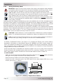
Figure 2-3 for the ME Series’ inverter/charger dimensions.
Away from sensitive electronic equipment - High-powered inverters can generate levels of RFI
(Radio Frequency Interference). Locate any electronic equipment susceptible to radio frequency
and electromagnetic interference as far away from the inverter as possible.
2.2 Mounting the Inverter
The inverter base can reach a temperature up to 90°C (194°F) and it is recommended that it should
be mounted on a non-combustible surface*. This surface and the mounting hardware must also be
capable of supporting at least twice the weight of the inverter. To meet regulatory requirements,
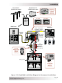
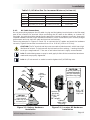
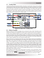
the ME Series must be mounted in one of the following positions, as shown in Figure 2-2:
above or under a horizontal surface (shelf or table)
or, on a vertical surface (wall) with the DC terminals to the right
or, on a vertical surface (wall) with DC terminals toward the bottom, MP-HOOD (inverter hood)
installed on the top, and either the ME-CB (Conduit Box) or MMP Series (single inverter) enclosure
installed on the inverter’s bottom.
Info: The ME-CB and the MMP Series enclosure prevent material from falling out the
bottom in the event of an internal fi re, and also allow suffi cient ventilation to prevent the
inverter from overheating under normal operating conditions. The MP-HOOD inverter
hood helps prevent items from falling inside, causing damage to the inverter.
Info: Magnum provides a backplate with a suitable surface for mounting the
inverter. The backplate also provides the ability to mount the MMP Series enclosure
(PN: BP-MMP).
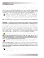
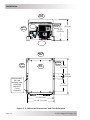
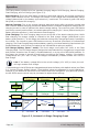
After determining the mounting position, refer to the physical dimensions as shown in Figure 2-3,
or use the base of the inverter as a template to mark your mounting screw locations.
* Non-combustible surface - A surface made of material that will not ignite, burn, support combustion, or
release fl ammable vapors when subjected to fi re or heat as per the ASTM E136 standard. For the most part,
these are materials that are largely comprised of inorganic matter such as stone, steel, iron, brick, tile,
concrete, slate, and glass. Avoid common building materials such as gypsum board, painted surfaces, wall
coverings, and any type of wood.
•
•
•
30
30
SHELF OR TABLE MOUNTED
(UP SIDE DOWN)
SHELF OR TABLE
MOUNTED
(RIGHT SIDE UP)
WALL MOUNTED
(DC TERMINALS TO THE RIGHT)
WALL MOUNTED
(DC TERMINALS
ON
THE BOTTOM*)
*WHEN THE INVERTER
IS MOUNTED IN THIS
POSITION, THE MP-
HOOD (
INVERTER
HOOD ON TOP), AND THE
ME-CB (
CONDUIT BOX
ON BOTTOM) OR MMP
SERIES
ENCLOSURE
MUST BE USED
Figure 2-2, Approved Mounting Positions

© 2010 Magnum Energy, IncPage 11
Installation
Figure 2-3, ME Series Dimensions and Side Reference
12 5/8" (32.1 cm)
12" (30.5 cm)
4 7/8"
(12.4 cm)
2"
(5.1 cm)
4 7/8"
(12.4 cm)
Keyhole slots
(x4) and
mounting holes
(x4) accept
up to 9/32"
(7 mm)
screw/bolt
13 3/4"
(34.9 cm)
8"
(20.3 cm)
6 5/8"
(16.8 cm)
RIGHT
S
IDE
BACK
S
IDE
RIGHT
S
IDE
LEFT
S
IDE
TOP
S
IDE
LEFT
S
IDE
TOP
S
IDE

Page 12
© 2010 Magnum Energy, Inc.
Installation
2.3 Wiring the Inverter - General Requirements
This section describes the requirements and recommendations for wiring the ME Series inverter/
charger. Before wiring the inverter/charger, read all instructions.
All wiring should meet all local codes and industry standards, and be performed by
qualifi ed personnel such as a licensed electrician.
The NEC (National Electric Code, ANSI/NFPA 70) for the United States and the CEC (Canadian
Electrical Code) for Canada provide safe wiring standards. The NEC/CEC list requirements for wire
sizes, overcurrent protection, and installation methods/standards.
Inverter/charger systems involve power from multiple sources (e.g., inverter, generator, shore
power, batteries, etc.) which makes the wiring more hazardous and challenging.
The input and output AC and DC circuits are isolated from the inverter chassis. The inverter system
grounding is the responsibility of the installer in accordance with the NEC/CEC and local codes.
WARNING: Ensure the sources of DC power (i.e., batteries) and AC power (shore
power or AC generator) are de-energized (i.e., breakers opened, fuses removed)
before proceeding – to prevent accidental shock.
2.3.1 Protecting Wire - Conduit Box
The AC and DC wires into and out of the inverter must be protected as required by code. This is
usually done by using jacketed wires. Magnum offers for purchase a DC conduit box (ME-CB) or
a single inverter enclosure (MMP Series) that includes the necessary AC and DC inverter breakers
that allow both the AC and DC conduit to be connected to the inverter.
Info: If using the ME-CB conduit box or the MMP enclosure, and the AC wires are
individual conductors (i.e., not jacketed), the strain reliefs can be removed and replaced
with 3/4” grommets.
2.3.2 Wiring Requirements
All conductors that are at risk for physical damage must be protected by tape, or placed
in a raceway.
Always check for existing electrical, plumbing, or other areas of potential damage prior to
making cuts in structural surfaces or walls.
Do not mix AC and DC wiring in the same panel unless specifi cally approved/designed for
both AC and DC wiring. Where DC wiring must cross AC or vice-versa, try to make the
wires 90° to one another at the crossing point.
Both AC and DC overcurrent protection must be provided as part of the installation.
The inverter requires a reliable negative and ground return path directly to the battery.
Use only copper wires with a minimum temperature rating of 90°C.
2.3.3 Wire Routing
Before connecting any wires, determine all wire routes to and from the inverter. Conductors passing
through walls, bulkheads, or other structural members must be protected to minimize insulation
damage, such as chafi ng. During installation, always avoid placing conductors near sources of
chafi ng caused by vibration or constant rubbing. Typical routing scenarios include:
AC input wiring from shore power source to the inverter
AC input wiring from an onboard generator (optional) to the inverter
DC input wiring from the batteries to the inverter
AC output wiring from the inverter to the coach’s AC main panel or to dedicated circuits
Battery Temperature Sensor cable from the inverter to the batteries
Remote control cable (optional) to the inverter
Ground wiring to and from the inverter
•
•
•
•
•
•
•
•
•
•
•
•
•

© 2010 Magnum Energy, IncPage 13
Installation
2.3.4 Torque Requirements
Torque all AC wiring connections to 16 in lbf (1.8 N-m). Torque DC cable connections from
10 to 12 ft lbf (13.6 to 16.3 N-m).
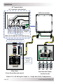
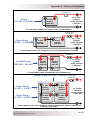
2.4 DC Wiring
This section describes the inverter’s required DC wire sizes, the recommended disconnect/overcurrent
protection, and how to make the DC connections to the inverter and the battery bank.
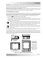
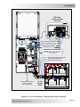
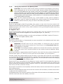
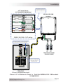
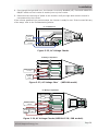
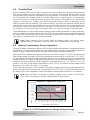
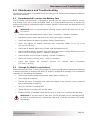
Refer to Figure 2-4 when connecting the DC wires.
WARNING: Even though DC voltage is “low voltage”, signifi cant hazards may be
present, particularly from short circuits of the battery system.
CAUTION: The inverter is NOT reverse polarity protected, which means that if the
negative and positive battery voltage is connected backwards to the inverter, the
inverter will likely be damaged. You should verify the correct voltage polarity using a
voltmeter BEFORE connecting the DC wires.
CAUTION: Before wiring the DC cables, review the safety information at the beginning
of this manual and the instructions below to ensure a safe and long-lived system.
Info: DO NOT connect the battery cables to the inverter until all wiring is complete.
The DC positive and negative cables connected to the inverter from the battery bank should
be tied together with wire ties or electrical tape approximately every 6 inches (153mm). This
helps improve the surge capability and reduces the effects of inductance, which improves the
inverter waveform and reduces the wear of the inverter’s fi lter capacitors.
Crimped and sealed copper ring terminal lugs with a 5/16” hole should be used to connect the
DC wires to the inverter’s DC terminals.
The battery bank voltage MUST match the DC voltage required by the inverter (i.e., 12-volt
battery bank for a 12-volt inverter), or the inverter may be damaged.
To ensure the maximum performance from the inverter, all connections from the battery bank
to the inverter should be minimized. The exceptions are the DC overcurrent disconnect in the
positive line, and a shunt in the negative line. Any other additional connection will contribute
to additional voltage drops and these extra connection points may loosen during use.
All wiring to the battery terminals should be checked periodically (once a month) for proper
tightness. The torque requirement for the DC terminals is between 10 to 12 ft lbf (13.6
to 16.3 N-m). If you don’t have a torque wrench, ensure all DC terminals are tight and
cannot move.
Be aware that overtightening or misthreading the nuts on the DC terminals can cause the
bolts to strip and snap/break off.
Make sure cables have a smooth bend radius and do not become kinked. Long cable runs
should follow existing wire runs if possible.
A brief spark or arc may occur when connecting the battery cables to the inverter DC terminals;
this is normal and due to the inverter’s internal capacitors being charged.
Color code the DC cables/wires with colored tape or heat shrink tubing: RED for positive (+),
WHITE for negative (-), and GREEN (or bare copper) for DC ground to avoid polarity problems.
•
•
•
•
•
•
•
•
•
•

Page 14
© 2010 Magnum Energy, Inc.
Installation
DC System Grounding point
[Electrode Conductor
(i.e., chassis/frame)]
ME Series
Inverter/Charger
front view
Battery Temp Sensor Cable
Inverter’s DC Negative Connection
Inverter’s DC Positive Connection
Inverter’s Equipment Ground Wire
BTS
BTS
12 volt
Battery
Bank
Battery Bank’s Equipment Ground Wire
Battery Bank’s Negative Cable
Battery Bank’s Positive Cable
MMP enclosure – for single inverter
installations (includes DC disconnect
breaker, DC shunt for battery monitor, and
inverter DC busbars).
Figure 2-4, DC and Battery Temperature Sensor Wiring
La pagina si sta caricando...
La pagina si sta caricando...
La pagina si sta caricando...
La pagina si sta caricando...
La pagina si sta caricando...
La pagina si sta caricando...
La pagina si sta caricando...
La pagina si sta caricando...
La pagina si sta caricando...
La pagina si sta caricando...
La pagina si sta caricando...
La pagina si sta caricando...
La pagina si sta caricando...
La pagina si sta caricando...
La pagina si sta caricando...
La pagina si sta caricando...
La pagina si sta caricando...
La pagina si sta caricando...
La pagina si sta caricando...
La pagina si sta caricando...
La pagina si sta caricando...
La pagina si sta caricando...
La pagina si sta caricando...
La pagina si sta caricando...
La pagina si sta caricando...
La pagina si sta caricando...
La pagina si sta caricando...
La pagina si sta caricando...
La pagina si sta caricando...
La pagina si sta caricando...
La pagina si sta caricando...
La pagina si sta caricando...
La pagina si sta caricando...
La pagina si sta caricando...
La pagina si sta caricando...
La pagina si sta caricando...
La pagina si sta caricando...
La pagina si sta caricando...
La pagina si sta caricando...
La pagina si sta caricando...
La pagina si sta caricando...
La pagina si sta caricando...
-
 1
1
-
 2
2
-
 3
3
-
 4
4
-
 5
5
-
 6
6
-
 7
7
-
 8
8
-
 9
9
-
 10
10
-
 11
11
-
 12
12
-
 13
13
-
 14
14
-
 15
15
-
 16
16
-
 17
17
-
 18
18
-
 19
19
-
 20
20
-
 21
21
-
 22
22
-
 23
23
-
 24
24
-
 25
25
-
 26
26
-
 27
27
-
 28
28
-
 29
29
-
 30
30
-
 31
31
-
 32
32
-
 33
33
-
 34
34
-
 35
35
-
 36
36
-
 37
37
-
 38
38
-
 39
39
-
 40
40
-
 41
41
-
 42
42
-
 43
43
-
 44
44
-
 45
45
-
 46
46
-
 47
47
-
 48
48
-
 49
49
-
 50
50
-
 51
51
-
 52
52
-
 53
53
-
 54
54
-
 55
55
-
 56
56
-
 57
57
-
 58
58
-
 59
59
-
 60
60
-
 61
61
-
 62
62


Magnum Energy ME Series Manuale del proprietario
- Categoria
- Adattatori di alimentazione
- Tipo
- Manuale del proprietario
in altre lingue
Documenti correlati
Altri documenti
-
BLACK DECKER BDV1085 Manuale del proprietario
-
BLACK DECKER BDV1084 Manuale del proprietario
-
Victron energy Quattro 5k 8k 10k 15k 100-100A 230V (firmware xxxx4xx) Manuale del proprietario
-
-
Dometic SI 1500 24V Manuale del proprietario
-
Bosch HEI8054U/04 Guida d'installazione
-
 Hach FL1500 Basic User Manual
-
-
BEL LET480 Guida d'installazione
-
Kensington 150 Manuale utente
