ProLights RA3000PROFILE Manuale utente
- Categoria
- Stroboscopi
- Tipo
- Manuale utente

USER MANUAL
MANUALE UTENTE
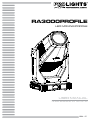
RA3000PROFILE
LED MOVING PROFILE
EN - IT

All rights reserved by Music & Lights S.r.l. No part of this instruction manual may be
reproduced in any form or by any means for any commercial use.
In order to improve the quality of products, Music&Lights S.r.l. reserves the right to modify the
characteristics stated in this instruction manual at any time and without prior notice.
All revisions and updates are available in the ‘manuals’ section on site www.musiclights.it
REV.01-04/18

1
RA3000PROFILE
Packing content
• RA3000PROFILE
• Power cable
• Mount bracket
• User manual
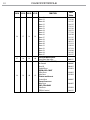
TABLE OF CONTENTS
Safety
General instructions
Warnings and installation precautions
1 Introduction
1. 1 Description
1. 2 Technical specications
1. 3 Operating elements and connections
2 Installation
2. 1 Mounting
3 Functions and settings
3. 1 Operation
3. 2 Basic
3. 3 Menu structure
3. 4 Linking
3. 5 DMX addressing conguration
3. 6 DMX mode conguration
3. 7 DMX addressing
3. 8 Wireless settings
3. 9 Ethernet
3. 10 Movement
3. 11 Screen
3. 12 Fixture settings
3. 13 Auto and manual test
3. 14 Reset of the function
3. 15 Adjust
3. 16 Informaion of the device
3. 17 Connection of the DMX line
3. 18 Construction of the DMX termination
3. 19 DMX control
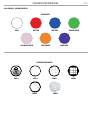
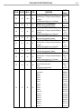
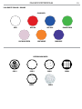
3. 20 Color - Gobos wheel
4 Maintenance
4. 1 Maintenance and cleaning the unit
4. 2 Fuse replacement
4. 3 Trouble shooting
2
2
3
3
6
7
8
8
9
12
12
12
12
13
13
14
14
14
15
15
16
16
17
17
18
23
24
24
25

RA3000PROFILE
2
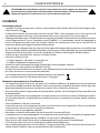
WARNING! Before carrying out any operations with the unit, carefully read this instruction
manual and keep it with cure for future reference. It contains important information about
the installation, usage and maintenance of the unit.
SAFETY
General instruction
• The products referred to in this manual conform to the European Community Directives and are there-
fore marked with .
• The unit is supplied with hazardous network voltage (230V~). Leave servicing to skilled personnel only.
Never make any modications on the unit not described in this instruction manual, otherwise you will
risk an electric shock.
• Connection must be made to a power supply system tted with ecient earthing (Class I appliance ac-
cording to standard EN 60598-1). It is, moreover, recommended to protect the supply lines of the units
from indirect contact and/or shorting to earth by using appropriately sized residual current devices.
• The connection to the main network of electric distribution must be carried out by a qualied electrical
installer. Check that the main frequency and voltage correspond to those for which the unit is designed
as given on the electrical data label.
• This unit is not for home use, only professional applications.
• Never use the xture under the following conditions:
- in places wet;
- in places subject to vibrations or bumps;
- in places with an ambient temperature of over 45°C.
• Make certain that no inammable liquids, water or metal objects enter the xture.
• Do not dismantle or modify the xture.
• All work must always be carried out by qualied technical personnel. Contact the nearest sales point for
an inspection or contact the manufacturer directly.
• If the unit is to be put out of operation denitively, take it to a local recycling
plant for a disposal which is not harmful to the environment.
Warnings and installation precautions
• If this device will be operated in any way dierent to the one described in this manual, it may suer
damage and the guarantee becomes void. Furthermore, any other operation may lead to dangers like
short circuit, burns, electric shock, etc.
• Before starting any maintenance work or cleaning the projector, cut o power from the main supply.
• Always additionally secure the projector with the safety rope. When carrying out any work, always com-
ply scrupulously with all the regulations (particularly regarding safety) currently in force in the country
in which the xture’s being used.
• For inside use only. Not designed for outside use.
• The minimum distance between the xture and surrounding walls must be more than 50 cm and the
air vents at the housing must not be covered in any case.
• Install the xture in a well ventilated place.
• Keep any inammable material at a safe distance from the xture.
• The maximum temperature that can be reached on the external surface of the tting, in a thermally
steady state, is high. After power o, please cool down over 15 minutes.
• Shields, lenses or ultraviolet screens shall be changed if they have become damaged to such an extent
that their eectiveness is impaired.
• The lamp (LED) shall be changed if it has become damaged or thermally deformed.
• Never look directly at the light beam. Please note that fast changes in lighting, e. g. ashing light, may
trigger epileptic seizures in photosensitive persons or persons with epilepsy.

3
RA3000PROFILE
- 1 - INTRODUCTION
1.1 DESCRIPTION
RA3000PROFILE combines solid-state technology in every single detail and it has been specically engi-
neered to be not only a high quality bright light but also silent. RA3000PROFILE is able to provide a real
25’000 lumen output with unprecedented beam evenness.
The 6000KLED engine has been custom designed to make the RA3000PROFILE hit a CRI of 90, TLCI of 92,
high R9 and TM30 making all skin tones and colours come to lifeon stage or in front of a camera.
The RA3000PROFILE’s CMY system delivers beautiful pastels, stunning saturated colours, powerful prima-
ries, one colour wheel provides split colours, and linear CTO allows the RA3000PROFILE to blend in with
traditional sources.
Packed with a full feature set, composed of a gobo wheel, animation wheel, iris, prism and dual linear
frost.
High-precision 4 blade shuttering system can be over-layed to provide endless combinations. The 19
element optics of the RA3000PROFILE are precision engineered for a perfect zoom, ideal edges and
maximum eciency.
The RA3000PROFILE is silent, bright, exible and precise.
FEATURES
• 1000W LED engine with 6000K CT featuring high CRI, TLCI, R9 and TM30
• 25’000 lumen xture output with at-eld projection
• Silent
1.2 TECHNICAL SPECIFICATIONS
LIGHT SOURCE
• Source: 1000W white LED
• CT: 6000K
• CRI: >90
• R9: 75
• Luminous ux: 25’000lm
• Lux: (50°) 1830 lux (6°) 83500lux @5m
• Source life expectancy: >50.000 h
• Other: TLCI: 92; TM30-15RF:88; TM30RG:99
OPTICS
• Zoom: 6-50° motorised linear zoom
• Lens diameter: 180mm
COLOUR SYSTEM
• Colour mixing: linear CMY
• CTC: linear CTO correction 3000~6000K
• Colour wheel: 6 dichroic lters + open
DYNAMIC EFFECTS
• Shutter system: 4 single blades: +/- 35°, complete system: +/- 45°
• Animation wheel: animation wheel with CW and CCW rotation
• Rotating gobos: 6 rotating gobos + open, interchangeable, indexing
• Gobo size: Outer diameter: 31,9mm, Gobo diameter: 27mm
• Circular prism: 4f with bi-directional rotation, indexing

RA3000PROFILE
4
• Frost: Dual frost lter system, 1° soft-edge frost gobo, 5° frost wash, with linear 0-100% frost lter
• Iris: 5-100% motorised linear iris
BODY
• Pan angle: 540°
• Tilt angle: 270°
• Pan/Tilt resolution: 8/16 bit
• Feedback: automatic repositioning after accidental movement
• Body: Flame-retardant PC
• Body colour: black
CONTROL
• Protocols: DMX512, RDM, Art-Net,W-DMX
• DMX channels: 38-39-40-41channel
• W-DMX: included, wireless solution receiver
• RDM: RDM ready for xture remote monitor and settings
• Display: black TFT high resolution display
• Firmware upgrade: yes, via USB-DMX interface (UPBOX1) not included
ELECTRONICS
• Dimmer: linear 0~100% electronic dimmer
• Strobe / shutter: 0-30 Hz, electronic
• Battery backup: battery backup for user operation without connecting to the main power
• Operating temperature: -10° ~ +45°
• Flicker: icker free operation
ELECTRICAL
• Power supply: 100-240V – 50/60Hz
• Power consumption (at 230V): 1288W
• Power consumption (at 120V): 1371W
• Power factor: (120W)1.0 - (230W) 0.97
PHYSICAL
• Cooling: combination of heat pipe cooling system and low noise fan
• Suspension and xing: Fast quick lock Omega bracket
• Pan / tilt lock: pan / tilt locking for transportation and maintenance
• Signal connection: Amphenol XLR 3p + 5p IN/OUT connectors
• Data connection: RJ45 IN/OUT
• Power connection: Neutrik powerCON IN/OUT connectors
• IP rating: 20
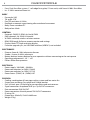
• Dimensions (WxHxD): 534x914x402mm
• Weight: 57kg

5
RA3000PROFILE
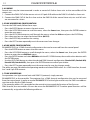
510mm
20,07in
914mm
35,98in
534mm
21,02in
402mm
15,82in
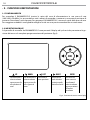
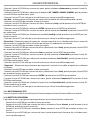
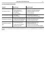
Illuminance at a Distance
6° - 50°
Lux Center Beam Angle: 6° - 50° Beam
Width
3m
5m
7m
10m
0m
231944/5083lx
83500/1830lx
42602/934lx
20875/458lx
0.309/2.73m
0.515/4.55m
0.721/6.37m
1.03/9.10m
Photometric data
Technical drawing
Fig.1

RA3000PROFILE
6
1
2
3
5
4
A
B
6
7
9
10
8
9
11
12
13
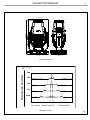
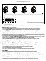
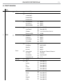
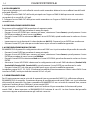
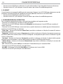
1.3 OPERATING ELEMENTS AND CONNECTIONS
1. MOVING HEAD
2. ROTARY ARM
3. TILT Mechanism Lock and Release
4. PAN Mechanism Lock and Release
5. HANDLE
6. CONTROL PANEL with TFT display
and 5 button used to access
the control panel functions and
manage them.
7. POWER IN (PowerCON TRUE
IN): for connection to a socket
(100-240V~/50-60Hz) via the
supplied mains cable.
8. MAIN FUSE HOLDER: replace a
burnt-out fuse by one of the same
type only.
9. EtherCON CONNECTORS IN / OUT
signal.
10. DMX IN (3-pole XLR):
1 = ground, 2 = DMX -, 3 = DMX +
11. DMX OUT ( 3-pole XLR):
1 = ground, 2 = DMX -, 3 = DMX +
12. DMX IN (5-pole XLR):
1 = ground, 2 = DMX-, 3 = DMX+,
4 N/C, 5 N/C.
13. DMX OUT (5-pole XLR):
1 = ground, 2 = DMX-, 3 = DMX+,
4 N/C, 5 N/C.
View A
View B
Fig.2

7
RA3000PROFILE
- 2 - INSTALLATION
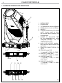
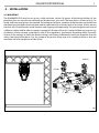
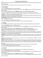
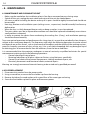
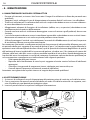
2.1 MOUNTING
The RA3000PROFILE may be set up on a solid and even surface. By means of the xing facilities of the
baseplate, the unit can also be mounted upside down to a cross arm. The base plate is shown in g.3. For
xing, stable mounting clips are required. According to the gure, the bolts of the brackets are placed into
the openings provided in the base plate and turned clockwise until they lock (to the stop). Always ensure
that the unit is rmly xed to avoid vibration and slipping while operating. The mounting place must be of
sucient stability and be able to support a weight of 10 times of the unit’s weight. When carrying out any
installation, always comply scrupulously with all the regulations (particularly regarding safety) currently
in force in the country in which the xture’s being used. Always additionally secure the projector with the
safety rope from falling down. For this purpose, fasten the safety rope at a suitable position so that the
maximum fall of the projector will be 20 cm.
Fig.3
CLAMP
OMEGA

RA3000PROFILE
8
- 3 - FUNCTIONS AND SETTINGS
3.1 OPERATION
Connect the supplied main cable to a socket (100-240V~/50-60Hz). The unit will run built-in program to
reset all motors to their home position. Shortly after that the RA3000PROFILE is ready for operation. To
switch o, disconnect the mains plug from the socket. For a more convenient operation it is recommend-
ed to connect the unit to a socket which can be switched on and o via light switch.
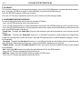
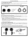
3.2 BASIC
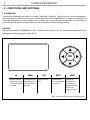
The control panel of RA3000PROFILE has a display and 5 buttons for the complete programming and
management of the projector menu (g.4).
Fig.4 - Functions of the buttons and display icons
UP DOWN LEFT RIGHT ENTER
Increases the value
displayed or passes
to the previous item
in a menu
Decreases the value
displayed or passes
to the next item in
the menu
Return to the top
level
Commute from
units, tens, hundred
in the menu
Conrms the
displayed value,
or activates the
displayed function,
or enters the
successive menu
OK

9
RA3000PROFILE
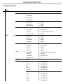
3.3 MENU STRUCTURE
MENU
1 CONNECT
ð
Address
ð
Value (1-472)
DMX Mode
ð
Standard 38Ch
Standard 40Ch
Extended 39Ch
Extended 41Ch
Wireless
ð
Receive On/O
ð
ON/OFF
Receive Reset
ð
NO/YES
Wireless to DMX
ð
NO/YES
Ethernet
ð
Universe
ð
Value (000-255)
Start Channel
ð
Value (001-512)
IP Address
ð
2.161.129.195/10.161.129.195
Ethernet to DMX
ð
YES/NO
2 SET UP
ð
Movement
ð
Pan Reverse
ð
NO/YES
Tilt Reverse
ð
NO/YES
Pan Feedback
ð
NO/YES
Tilt Feedback
ð
NO/YES
Screen
ð
Backlight
ð
On/10s/20s/ 30s
Flip Display
ð
NO/YES/AUTO
Warn Cue
ð
ON/OFF
Key Lock
ð
NO/YES
Fixture
ð
Dimmer Mode
ð
OFF/Dimmer 1/Dimmer 2/Dimmer 3
Fans Mode
ð
Auto/High
Theater Mode
ð
Auto/Silent/O
Temperature unit
ð
°C /°F
Auto Test
ð
Auto Test …
Manual Test
ð
Pan
ð
Value (000-255)
Pan Fine
ð
Value (000-255)
Tilt
ð
Value (000-255)
Tilt Fine
ð
Value (000-255)
P/T Speed
ð
Value (000-255)
Dimmer
ð
Value (000-255)
Shutter
ð
Value (000-255)
Cyan
ð
Value (000-255)
Magenta
ð
Value (000-255)
Yellow
ð
Value (000-255)

RA3000PROFILE
10
CTO
ð
Value (000-255)
Color
ð
Value (000-255)
Gobo
ð
Value (000-255)
RGobo
ð
Value (000-255)
PrismRot.
ð
Value (000-255)
Eect
ð
Value (000-255)
REect
ð
Value (000-255)
Focus
ð
Value (000-255)
Zoom
ð
Value (000-255)
Frost 1
ð
Value (000-255)
Frost 2
ð
Value (000-255)
Iris
ð
Value (000-255)
Reload Default
ð
Fr.shutters Rot.
ð
Value (000-255)
Fr.shutter 1 Move.
ð
Value (000-255)
Fr.shutter 1 Swiv.
ð
Value (000-255)
Fr.shutter 2 Move.
ð
Value (000-255)
Fr.shutter 2 Swiv.
ð
Value (000-255)
Fr.shutter 3 Move.
ð
Value (000-255)
Fr.shutter 3 Swiv.
ð
Value (000-255)
Fr.shutter 4 Move.
ð
Value (000-255)
Fr.shutter 4 Swiv.
ð
Value (000-255)
4 ADVANCED
ð
Reset
ð
All
Pan
Tilt
Cyan
Magenta
Yellow
CTO
Color
Gobo
Prism
Eect
Focus
Zoom

11
RA3000PROFILE
Frost
Iris
Fr.shutters Rot.
Fr.shutter 1 M1
Fr.shutter 1 M2
Fr.shutter 2 M1
Fr.shutter 2 M2
Fr.shutter 3 M1
Fr.shutter 3 M2
Fr.shutter 4 M1
Fr.shutter 4 M2
Adjust Value (000-255)
Factory Reload
ð
NO/YES
ð
Value (000-255)
4
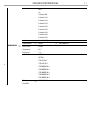
INFORMATION
ð
Fixture Time 0-9999
Temperature 58 °C
Fans Speed **%
Software Version DISP- V0.3
NET-V0.2
CTR1-XY- V0.2
CTR2-LED-V0.2
CTR3-MOTOR-V0.2
CTR4-MOTOR-V0.2
CTR5-MOTOR-V0.2
CTR6-MOTOR-V0.2
CTR7-MOTOR-V0.2
UID
ð
15D00221****
View DMX

RA3000PROFILE
12
3.4 LINKING
Several units may be interconnected in order to control all further slave units to the same eect of the
master unit.
1. Connect the DMX OUT of the master unit via 3/5-pole XLR cable to the DMX IN of the rst slave unit.
2. Connect the DMX OUT of the rst slave unit to the DMX IN of the second slave unit, etc. until all units
are connected in a chain.
3.5 DMX ADDRESSING CONFIGURATION
To enter the DMX mode, follow these steps:
• Press the ENTER button to access the main menu.
• Press the UP/DOWN button to scroll the menu, select the Connect icon, then press the ENTER button to
enter the next menu.
• Press the UP/DOWN button to scroll through the menu, select the Address and press the ENTER key.
• Press the arrow keys to select the desired value (001-512).
• Press the ENTER key to conrm the setting.
• Press the LEFT button repeatedly to exit the menu and save changes.
3.6 DMX MODE CONFIGURATION
RA3000PROFILE has 4 DMX channel congurations that can be accessed from the control panel.
• Press the ENTER button to access the main menu.
• Press the UP/DOWN button to scroll through the menu, select the Connect icon, then press the ENTER
button to enter the next DMX Mode menu.
• Press the ENTER button and select DMX Mode with the UP/ DOWN button, then conrm the selection with
the ENTER button.
• Use the UP/DOWN button to select the desired DMX channel conguration (Standard 38Ch, Standard 40Ch,
Extended 39Ch, Extended 41Ch), then press the ENTER button to conrm your choice.
• Press the LEFT button repeatedly to exit the menu and to save the changes made.
The tables on page 20 indicate the operating modes and related DMX values. As a DMX interface, the unit
has 3 and 5-pin XLR contacts.
3.7 DMX ADDRESSING
For operation via a light control unit with DMX512 protocol, simply connect
RA3000PROFILE to the controller. The projector has a DMX channel conguration that can be accessed
from the control panel. In order to control RA3000PROFILE with a light control unit, the DMX start address
must be set for the rst DMX channel.
If, for example, address 33 is provided on the control unit to control the function of the rst one
DMX channel, the start address 33 must be set on the RA3000PROFILE. The other panel functions will be
automatically assigned to the following addresses.

13
RA3000PROFILE
3.8 WIRELESS SETTINGS
• To enter the wireless setting mode press the ENTER button until the display shows Connect, then select
Wireless, then press the ENTER button.
• Select the Wireless Receive function using the UP/DOWN buttons, then press the ENTER button.
• To activate the Wireless reception mode, use the UP/DOWN buttons and select the On option.
• Press the ENTER button to conrm the selection.
• Press the LEFT button to go back or wait a few seconds to exit the setup menu.
• NOTE - Once you have performed these steps, you must synchronize with any WiFi unit with which you
want to communicate by pressing the sync button on it. At this point connect the DMX console to the WiFi
unit to open the communication with the RA3000PROFILE.
• To reset the unit, select the Wireless Reset function using the UP/DOWN buttons, press the ENTER button
until the display shows Connect, then select Wireless, then press the ENTER button.
• Select the Wireless Reset function using the UP/DOWN buttons, then press the ENTER button.
• To activate the mode use the UP / DOWN keys and select the Yes option.
• Press the ENTER button to conrm the selection.
• Press the LEFT button to go back or wait a few seconds to exit the setup menu.
To activate the Wireless to DMX function, use the UP / DOWN buttons to press the ENTER button until the
display shows Connect, then select Wireless, then press the ENTER button.
• Select the Wireless to DMX function using the UP/DOWN buttons, then press the ENTER button.
• To activate the mode use the UP/DOWN buttons and select the Yes option.
• Press the ENTER button to conrm the selection.
• Press the LEFT button to go back or wait a few seconds to exit the setup menu.
3.9 ETHERNET
For the ArtNet settings to be assigned to the unit, refer to the following menu section.
• Press the UP/DOWN button to scroll through the menu, select Connect, then press the ENTER button ac-
cess the next Ethernet menu with the UP / DOWN button, then press the ENTER button.
• Use the UP/DOWN buttons to select one of the following settings: Universe, Start Channel, IP Address, Ethernet
to DMX.
• Press the ENTER button to conrm the selection and enter the sub menu.
• Set the desired value for the selected function using the UP/DOWN buttons. Then press
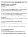
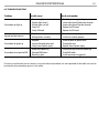
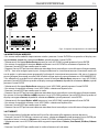
Fig.5 - Example of a DMX 38-channel conguration
DMX Address: 185DMX Address: 109DMX Address: 71 DMX Address: 147
. . . . . . . . . . . .
DMX512 Controller

RA3000PROFILE
14
the ENTER button.
• Press the LEFT button to go back or wait a few seconds to exit the setup menu.
3.10 MOVEMENT
• Press the ENTER button to access the main menu.
• Press the UP/DOWN button to scroll through the menu, select Set Up, then press the ENTER button access
the next menu.
• Press the UP/DOWN button to select Movement and press the ENTER button to proceed.
• Select the proposed option with the UP/DOWN button and press the ENTER button to conrm.
- Pan Reverse - Rotation in the opposite direction of the moving head. NO to deactivate the function (nor-
mal setting); YES to activate the function (Pan Reverse).
- Tilt Reverse - Inclination in the opposite direction of the moving head. NO to deactivate the function (nor-
mal setting), YES to activate the function (Tilt Reverse).
- Pan/Tilt Feedbacks - Rearrange Pan/Tilt position after accidental shift. Select NO for deactivate the function
or YES to activate the function.
• Press the ENTER button to conrm the selection.
• Press the LEFT button repeatedly to exit the menu and to save the changes made.
3.11 SCREEN
It is possible to modify the following parameters, related to the display, following the same procedure:
• Press the ENTER button to access the main menu.
• Press the UP/DOWN button to scroll through the menu, select Set Up, then press the ENTER button access
the next menu.
• Press the UP/DOWN button to select Screen and press the ENTER button to proceed.
• Select the proposed option with the UP/DOWN button and press the ENTER button to conrm.
- Backlight - Auto O display backlight. This function allows you to switch o automatically
the backlighting of the display after a certain time which can be set using the directional keys. To have the
display always on select On or set a value between those shown (10s, 20s, 30s) to turn o the display once
the chosen time has elapsed, after exiting the menu.
- Flip Display - Display orientation. This feature allows you to rotate the display by 180 ° to get a better view
of the display when the unit is hanging upside down. Select YES to activate the function or NO to deacti-
vate it.
- Warn Cue - Warning of error. Use the arrow keys to select OFF or ON depending on whether or not the
display shows error warnings.
- Key lock - With this function, you can lock the keys on the control panel to prevent, for example, tampering
with the settings. If this function is activated, the keys are locked automatically. To disable or temporarily
disable or disable the key lock function, press the keys in the following order to regain access to the menu
commands:
UP, DOWN, UP, DOWN, ENTER, ENTER. Select YES to activate the function or NO to deactivate it.
• Press the ENTER button to conrm the selection.
• Press the LEFT key repeatedly to exit the menu and to save the changes made.
3.12 FIXTURE
Dimmer Mode - select this function to choose and simulate dierent dimming curves:
• Press the ENTER button to access the main menu.
• Press the UP/DOWN button to scroll through the menu, select Set Up, then press the ENTER button access
the next menu.
• Press the UP/DOWN button to select Fixture and press the ENTER button to proceed.
• Press the UP/DOWN button to scroll through the menu, then select Dimmer mode and press the ENTER
button to conrm.

15
RA3000PROFILE
• Press the UP/DOWN button to select the mode (OFF - DIMMER1 - DIMMER2 - DIMMER3), then press the ENTER
button to conrm your choice.
• Press the LEFT button repeatedly to exit the menu and to save the changes made.
- Fans Mode - select this function to set the fan operating mode:
• Press the ENTER button to access the main menu.
• Press the UP/DOWN button to scroll through the menu, select Set Up, then press the ENTER button access
the next menu.
• Press the UP/DOWN button to select FIXTURE and press the ENTER button to proceed.
• Press the UP/DOWN button to scroll through the menu, then select Fans Mode and press the ENTER button
to conrm.
• Press the UP/DOWN button to select the Auto High mode, then press the ENTER button to conrm your
choice.
• Press the LEFT button repeatedly to exit the menu and to save the changes made.
- Theater Mode - Select this function for theatrical situations or in which you want less noise; the output of
the LED will be limited to limit the heating and the fans:
• Press the ENTER button to access the main menu.
• Press the UP/DOWN button to scroll through the menu, select the Set Up icon, then press the ENTER but-
ton to access the next menu.
• Press the UP/DOWN button to select Fixture and press the ENTER button to proceed.
• Press the UP/DOWN button to scroll through the menu, then select Theater Mode and press the ENTER
button to conrm.
• Press the UP/DOWN button to select the desired option (Auto / Silent / O), then press the ENTER button to
conrm your choice.
• Press the LEFT button repeatedly to exit the menu and to save the changes made.
- Temperature - Select this function to set the unit of measurement of the temperature shown on the display:
• Press the ENTER button to access the main menu.
• Press the UP/DOWN button to scroll through the menu, select the Set Up icon, then press the ENTER but-
ton to access the next menu.
• Press the UP/DOWN button to select FIXTURE and press the ENTER button to proceed.
• Press the UP/DOWN button to scroll through the menu, then select Temperature °C/F and press the ENTER
button to conrm.
• Press the UP / DOWN button to select the Celsius / Fahrenheit measurement unit, then press the ENTER but-
ton to conrm the selection.
• Press the LEFT buttton repeatedly to exit the menu and to save the changes made.
3.13 AUTO E MANUAL TEST
Through these menus it is possible to test the functioning of all the functions of the moving head.
3.14 RESET OF THE FUNCTIONS
You can start a preset program to restore the selected function:
• Press the ENTER button to access the main menu.
• Press the UP/DOWN button to scroll through the menu, select the Advanced icon, then press the ENTER
button to enter the next menu.
• Press the UP/DOWN button to select Reset and press the ENTER button to access the next menu.
• Press the UP/DOWN button to scroll through the menu, then select the function you want to reset be-
tween those.
• Press the ENTER button to conrm the selection and wait for the selected function to be restored.
• Press the LEFT button repeatedly to exit the menu and to save the changes made.

RA3000PROFILE
16
3.15 ADJUST
This function allows you to change all parameters. Press the UP/DOWN buttons to select one of the param-
eters and press ENTER to change its value (000-999) using the UP/DOWN buttons.
Press the ENTER button to conrm your choice.
Press the LEFT button repeatedly to exit the menu and to save the changes made.
3.16 INFORMATION ON THE DEVICE
To view all the information on the device, proceed as follows:
• Press the ENTER button to access the main menu.
• Press the UP/DOWN button to select Information, then press the ENTER button to access the next menu.
• Press the UP/DOWN button to scroll through the menu, then select one of the following information and
press the ENTER button to display it.
- Fixture Time - Through the Fixture Time function, the operating time of the projector can be shown on the
display.
- Temperature - Through the Temperature function it is possible to display on the display the temperature
inside the moving head, where the lamp is located. The temperature can be displayed in degrees Celsius
or Fahrenheit.
- Fans Speed - Through the Fans Speed function it is possible to display on the display the fan speed present
near the lamp. The speed measurement is expressed in RPM (revolutions per minute).
- Software Version - Through the Software Version function, the version of the installed software can be viewed
on the display.
- UID - Select the UID function to display the identication ID for the RDM control.
• Press the LEFT button repeatedly to exit the menu.
- DMX View - Select the View DMX function to display all DMX menu.
• Press the LEFT button repeatedly to exit the menu.

17
RA3000PROFILE
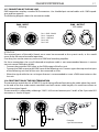
3.17 CONNECTION OF THE DMX LINE
DMX connection employs standard XLR connectors. Use shielded pair-twisted cables with 120Ω imped-
ance and low capacity.
The following diagram shows the connection mode:
Fig.7
DMX - OUTPUT
XLR socket
DMX - INPUT
XLR plug
Pin1 : GND - Shield
Pin2 : - Negative
Pin3 : + Positive
Pin4 : N/C
Pin5 : N/C
ATTENTION
The screened parts of the cable (sleeve) must never be connected to the system’s earth, as this would
cause faulty xture and controller operation.
Over long runs can be necessary to insert a DMX level matching amplier.
For those connections the use of balanced microphone cable is not recommended because it cannot
transmit control DMX data reliably.
• Connect the controller DMX input to the DMX output of the rst unit.
• Connect the DMX output to the DMX input of the following unit. Connect again the output to the input
of the following unit until all the units are connected in chain.
• When the signal cable has to run longer distance is recommended to insert a DMX termination on the
last unit.
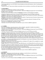
3.18 CONSTRUCTION OF THE DMX TERMINATION
The termination avoids the risk of DMX 512 signals being reected back along the cable when they reach-
es the end of the line: under certain conditions and with certain cable lengths, this could cause them to
cancel the original signals.
The termination is prepared by soldering a 120Ω 1/4 W resistor between pins 2 and 3 of the 5-pin male XLR
connector, as shown in gure.
Fig.8
Example:
5 pin XLR connector
4

RA3000PROFILE
18
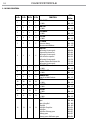
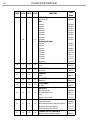
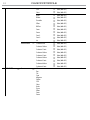
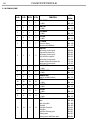
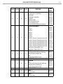
3.19 DMX CONTROL
38 Ch 39 Ch 40 Ch 41 Ch FUNCTION
DMX
Value
1 1 1 1
PAN COARSE
0~100% 000 - 255
2 2 2 2
PAN FINE
0~100% 000 - 255
3 3 3 3
TILT COARSE
0~100% 000 - 255
4 4 4 4
TILT FINE
0~100% 000 - 255
5 5 5 5
P/T SPEED
Fastest to slowest
Movement with Blackout
000 - 250
251 - 255
6 6 6 6
SHUTTER
No function (shutter open)
Shutter eect slow to fast
No function (shutter open)
Pulse-eect in sequences
No function (shutter open)
Random Shutter eect slow to fast
No function (shutter open)
000-010
011-082
083-093
094-163
164-174
175-244
245-255
7 7 7 7
DIMMER 8BIT
0~100% 000 - 255
8 8 8 8
DIMMER 16BIT
0~100% 000 - 255
9 9 9 9
DIMMER FADE
Snap 0% to 100% fade out 000 - 255
10 10 10 10
CYAN
0~100% 000 - 255
11 11 11 11
MAGENTA
0~100% 000 - 255
12 12 12 12
YELLOW
0~100% 000 - 255
13 13 13 13
CTO
0~100% 000 - 255
14 14 14 14
COLOR
Open
Open+Deep Red
Deep Red
Deep Red+Deep blue
Deep Blue
Deep Blue+Primary green
Primary green
Primary green+Half minus green
000 - 004
005 - 009
010 - 013
014-018
019-022
023-027
028-031
032-036
La pagina sta caricando ...
La pagina sta caricando ...
La pagina sta caricando ...
La pagina sta caricando ...
La pagina sta caricando ...
La pagina sta caricando ...
La pagina sta caricando ...
La pagina sta caricando ...
La pagina sta caricando ...
La pagina sta caricando ...
La pagina sta caricando ...
La pagina sta caricando ...
La pagina sta caricando ...
La pagina sta caricando ...
La pagina sta caricando ...
La pagina sta caricando ...
La pagina sta caricando ...
La pagina sta caricando ...
La pagina sta caricando ...
La pagina sta caricando ...
La pagina sta caricando ...
La pagina sta caricando ...
La pagina sta caricando ...
La pagina sta caricando ...
La pagina sta caricando ...
La pagina sta caricando ...
La pagina sta caricando ...
La pagina sta caricando ...
La pagina sta caricando ...
La pagina sta caricando ...
La pagina sta caricando ...
La pagina sta caricando ...
La pagina sta caricando ...
La pagina sta caricando ...
La pagina sta caricando ...
La pagina sta caricando ...
-
 1
1
-
 2
2
-
 3
3
-
 4
4
-
 5
5
-
 6
6
-
 7
7
-
 8
8
-
 9
9
-
 10
10
-
 11
11
-
 12
12
-
 13
13
-
 14
14
-
 15
15
-
 16
16
-
 17
17
-
 18
18
-
 19
19
-
 20
20
-
 21
21
-
 22
22
-
 23
23
-
 24
24
-
 25
25
-
 26
26
-
 27
27
-
 28
28
-
 29
29
-
 30
30
-
 31
31
-
 32
32
-
 33
33
-
 34
34
-
 35
35
-
 36
36
-
 37
37
-
 38
38
-
 39
39
-
 40
40
-
 41
41
-
 42
42
-
 43
43
-
 44
44
-
 45
45
-
 46
46
-
 47
47
-
 48
48
-
 49
49
-
 50
50
-
 51
51
-
 52
52
-
 53
53
-
 54
54
-
 55
55
-
 56
56


ProLights RA3000PROFILE Manuale utente
- Categoria
- Stroboscopi
- Tipo
- Manuale utente
in altre lingue
- English: ProLights RA3000PROFILE User manual
Documenti correlati
-
ProLights RA3000PROFILE Manuale utente
-
-
-
-
-
-
-
-
-
