ProLights RA2000PROFILE Manuale utente
- Categoria
- Stroboscopi
- Tipo
- Manuale utente

USER MANUAL
MANUALE UTENTE
RA2000PROFILE
LED MOVING PROFILE
EN - IT

All rights reserved by Music & Lights S.r.l. No part of this instruction manual may be
reproduced in any form or by any means for any commercial use.
In order to improve the quality of products, Music&Lights S.r.l. reserves the right to modify the
characteristics stated in this instruction manual at any time and without prior notice.
All revisions and updates are available in the ‘manuals’ section on site www.musiclights.it
REV .02-05/19

1
RA2000PROFILE
Packing content
• RA2000PROFILE
• Power cable
• OS25 (2 pcs)
• Safety cable
• User manual
TABLE OF CONTENTS
Safety
General instructions
Warnings and installation precautions
1 Introduction
1. 1 Description
1. 2 Technical specifications
1. 3 Operating elements and connections
2 Installation
2. 1 Mounting
3 Functions and settings
3. 1 Operation
3. 2 Basic
3. 3 Menu structure
3. 4 Linking
3. 5 DMX addressing configuration
3. 6 DMX mode configuration
3. 7 DMX addressing
3. 8 Wireless settings
3. 9 Ethernet
3. 10 Movement
3. 11 Screen
3. 12 Fixture settings
3. 13 Fans mode
3. 14 Led red mode
3. 15 Auto and manual test
3. 16 Reset of the function
3. 17 Adjust
3. 18 Informaion of the device
3. 19 DMX view
3. 20 Connection of the DMX line
3. 21 Construction of the DMX termination
3. 22 DMX control
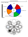
3. 23 Color - Gobos wheel
4 Maintenance
4. 1 Maintenance and cleaning the unit
4. 2 Fuse replacement
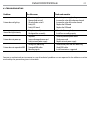
4. 3 Trouble shooting
2
2
3
3
6
7
8
8
9
12
12
12
12
13
14
14
14
15
15
16
16
16
17
17
17
18
18
19
25
26
26
27

RA2000PROFILE
2
WARNING! Before carrying out any operations with the unit, carefully read this instruction
manual and keep it with cure for future reference. It contains important information about
the installation, usage and maintenance of the unit.
SAFETY
General instruction
• The products referred to in this manual conform to the European Community Directives and are there-
fore marked with
.
• The unit is supplied with hazardous network voltage (230V~). Leave servicing to skilled personnel only.
Never make any modifications on the unit not described in this instruction manual, otherwise you will
risk an electric shock.
• Connection must be made to a power supply system fitted with efficient earthing (Class I appliance ac-
cording to standard EN 60598-1). It is, moreover, recommended to protect the supply lines of the units
from indirect contact and/or shorting to earth by using appropriately sized residual current devices.
• The connection to the main network of electric distribution must be carried out by a qualified electrical
installer. Check that the main frequency and voltage correspond to those for which the unit is designed
as given on the electrical data label.
• This unit is not for home use, only professional applications.
• Never use the fixture under the following conditions:
- in places wet;
- in places subject to vibrations or bumps;
- in places with an ambient temperature of over 45°C.
• Make certain that no inflammable liquids, water or metal objects enter the fixture.
• Do not dismantle or modify the fixture.
• All work must always be carried out by qualified technical personnel. Contact the nearest sales point
for an inspection or contact the manufacturer directly.
• If the unit is to be put out of operation definitively, take it to a local recycling
plant for a disposal which is not harmful to the environment.
Warnings and installation precautions
• If this device will be operated in any way different to the one described in this manual, it may suffer
damage and the guarantee becomes void. Furthermore, any other operation may lead to dangers like
short circuit, burns, electric shock, etc.
• Before starting any maintenance work or cleaning the projector, cut off power from the main supply.
• Always additionally secure the projector with the safety rope. When carrying out any work, always
comply scrupulously with all the regulations (particularly regarding safety) currently in force in the
country in which the fixture’s being used.
• For inside use only. Not designed for outside use.
• The minimum distance between the fixture and surrounding walls must be more than 50 cm and the
air vents at the housing must not be covered in any case.
• Install the fixture in a well ventilated place.
• Keep any inflammable material at a safe distance from the fixture.
• The maximum temperature that can be reached on the external surface of the fitting, in a thermally
steady state, is high. After power off, please cool down over 15 minutes.
• Shields, lenses or ultraviolet screens shall be changed if they have become damaged to such an extent
that their effectiveness is impaired.
• The lamp (LED) shall be changed if it has become damaged or thermally deformed.
• Never look directly at the light beam. Please note that fast changes in lighting, e. g. flashing light, may
trigger epileptic seizures in photosensitive persons or persons with epilepsy.
• This product was designed and built strictly for the use indicated in this documentation. Any other use,
not expressly indicated here, could compromise the good condition/operation of the product and/or
be a source of danger.
• We decline any liability deriving from improper use of the product.

3
RA2000PROFILE
- 1 - INTRODUCTION
1.1 DESCRIPTION
The RA2000PROFILE has been designed in response to feedback from global users and by lighting de-
signers. A universal moving profile/spot that lighting designers and users can use for theatrical, touring
and TV productions. Powerful but silent, compact but fully equipped with both framing shutters and
animation wheel, all whilst delivering a superior light quality, the RA2000PROFILE is an indispensable
tool for any show.
The 6000K LED engine has been custom engineered to make the RA2000PROFILE hit a 13.000-lumen
output, keeping a native CRI of 94, TLCI of 92, high R9 and TM30 making all skin tones and colours come
to life on stage or in front of a camera.
The RA2000PROFILE’s CMY system delivers beautiful pastels, stunning saturated colours, powerful prima-
ries, one colour wheel provides split colours, and linear CTO allows the RA2000PROFILE to blend in with
traditional sources.
Packed with a full feature set composed of a gobo wheel, adjustable framing shutters, animation wheel,
iris, prism and dual linear frost. The highly efficient optical system delivers a 1:8 zoom from 6° to 48°, and
crisp focus to perfectly merge multi-layer effects.
The RA2000PROFILE is the real embodiment of solid-state LED technology.
1.2 TECHNICAL SPECIFICATIONS
LIGHT SOURCE
• Source: 540W LED
• CT: 6000K
• CRI: 94
• R9: 78
• Luminous flux: 13000lm
• Lux: (6°) 32200 lux - (48°) 916lux @5m
• Source life expectancy: 60000
• Other: TM-30-15RF/RG: 90/99 - TLCI: (6°) 92.7 - (48°) 93.3
OPTICS
• Zoom: 6°-48° motorised linear zoom
• Lens diameter: 120mm
• Focus: motorised
COLOUR SYSTEM
• Colour mixing: linear CMY
• CTC: amber shift activation by DMX and linear CTO correction 2700~6000K
• Colour wheel: 6 dichroic filters + open
DYNAMIC EFFECTS
• Shutter system: 4 shutter blades with position and ±30° angle adjustment, ±45° rotation of the com-
plete framing system
• Animation wheel: animation wheel with CW and CCW rotation
• Rotating gobos: 7 rotating gobos + open, interchangeable, indexing
• Gobo size: Ø 26.9 mm - img Ø 21.5 mm - 1.1 mm
• FX generator: shutter macros with adjustable speed
• Circular prism: 4f with bi-directional rotation, indexing

RA2000PROFILE
4
• Frost: Dual frost filter system, 1° soft-edge frost gobo, 5° frost wash, with linear 0-100% frost filter frost
unit to soften the beam edge
• Iris: 5 - 100% motorised linear iris
• Static colour mode: selection of static colour
• Manual colour mode: manual adjustment of dimmer and strobe
BODY
• Pan angle: 540°
• Tilt angle: 270°
• Pan/Tilt resolution: 16 bit
• Feedback: automatic repositioning after accidental movement
• Body colour: black finishing
CONTROL
• Protocols: DMX512, RDM, Art-Net,W-DMX
• DMX channels: 38 / 39 / 40 / 41 / 44 channel
• W-DMX: included, wireless solution receiver
• RDM: RDM ready for fixture remote monitor and settings
• Display: TFT high resolution colour display with autoflip
• Firmware upgrade: yes, via USB-DMX interface (UPBOX1) not included
ELECTRONICS
• Dimmer: linear 0~100% electronic dimmer
• Strobe / shutter: 1-30 Hz, electronic
• Battery backup: battery backup for user operation without connecting to the main power
• Operating temperature: -10° ~ +50°
• Flicker: flicker free operation
ELECTRICAL
• Power consumption: 150 W / 600 W
• Power supply: 100-240V – 50/60Hz
• Power consumption (at 230V): (static) 574 W - (dynamic) 620W
• Power consumption (at 120V): (static) 606 W - (dynamic) 640W
• Output (at 230V): 4 units on a single power line
• Output (at 120V): 2 units on a single power line
• Power factor: pF 0.95 @ 230 V - pF 0.99 @ 120 V
PHYSICAL
• Cooling: combination of heat pipe cooling system and low noise fan
• Sospension and fixing: hanging bracket for floor positioning with “Quick-Lock” system
• Pan / tilt lock: pan / tilt locking for transportation and maintenance
• Signal connection: Amphenol XLR 5p IN/OUT connectors
• Data connection: Art-Net RJ45 IN/OUT
• Power connection: Neutrik powerCON TRUE1 IN/OUT connectors
• IP rating: 20
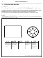
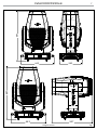
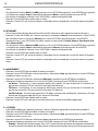
• Dimensions (WxHxD): 443x697x507mm
• Weight: 31.38kg

5
RA2000PROFILE
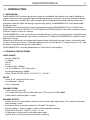
443
697
293
443
697
507
Technical drawing Fig.1

RA2000PROFILE
6
1
2
3
5
4
14
15
6 7
8
9 10 11
11 12
13
7
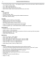
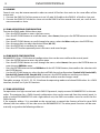
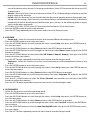
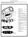
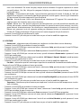
1.3 OPERATING ELEMENTS AND CONNECTIONS
1. MOVING HEAD
2. TILT Mechanism Lock and Release
3. ROTARY ARM
4. PAN Mechanism Lock and Release
5. BASE
6. HANDLE
7. CONTROL PANEL with TFT display
and 5 button used to access
the control panel functions and
manage them.
8. POWER IN (PowerCON TRUE
IN): for connection to a socket
(100-240V~/50-60Hz) via the
supplied mains cable.
9. POWER OUT (PowerCON
TRUE OUT): power output for
connection of multiple units in
series.
10. MAIN FUSE HOLDER: replace a
burnt-out fuse by one of the same
type only.
11. EtherCON CONNECTORS IN / OUT
signal.
12. DMX IN (5-pole XLR):
1 = ground, 2 = DMX-, 3 = DMX+,
4 N/C, 5 N/C.
13. DMX OUT (5-pole XLR):
1 = ground, 2 = DMX-, 3 = DMX+,
4 N/C, 5 N/C.
14. ANTENNA
15. RUBBER FEET
Fig.2

7
RA2000PROFILE
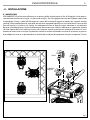
- 2 - INSTALLATION
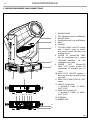
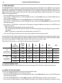
2.1 MOUNTING
The RA2000PROFILE may be set up on a solid and even surface. By means of the fixing facilities of the
baseplate, the unit can also be mounted upside down to a cross arm. The base plate is shown in fig.3. For
fixing, stable mounting clips are required. According to the figure, the bolts of the brackets are placed into
the openings provided in the base plate and turned clockwise until they lock (to the stop). Always ensure
that the unit is firmly fixed to avoid vibration and slipping while operating. The mounting place must be of
sufficient stability and be able to support a weight of 10 times of the unit’s weight. When carrying out any
installation, always comply scrupulously with all the regulations (particularly regarding safety) currently
in force in the country in which the fixture’s being used. Always additionally secure the projector with the
safety rope from falling down. For this purpose, fasten the safety rope at a suitable position so that the
maximum fall of the projector will be 20 cm.
Fig.3
CLAMPS
OMEGA

RA2000PROFILE
8
- 3 - FUNCTIONS AND SETTINGS
3.1 OPERATION
Connect the supplied main cable to a socket (100-240V~/50-60Hz). The unit will run built-in program
to reset all motors to their home position. Shortly after that the RA2000PROFILE is ready for operation.
To switch off, disconnect the mains plug from the socket. For a more convenient operation it is recom-
mended to connect the unit to a socket which can be switched on and off via light switch.
NOTE: remove the pan and tilt lock before connecting the RA2000PROFILE to the power supply.
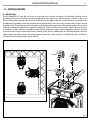
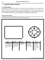
3.2 BASIC
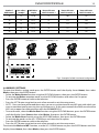
The control panel of RA2000PROFILE has a display and 5 buttons for the complete programming and
management of the projector menu (fig.4).
Fig.4 - Functions of the buttons and display icons
UP
DOWN LEFT RIGHT ENTER
Increases the value
displayed or passes
to the previous item
in a menu
Decreases the value
displayed or passes
to the next item in
the menu
Return to the top
level
Commute from
units, tens, hundred
in the menu
Confirms the
displayed value,
or activates the
displayed function,
or enters the
successive menu

9
RA2000PROFILE
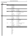
3.3 MENU STRUCTURE
MENU
1 CONNECT
ð
Address
ð
Value (1-512)
DMX Mode
ð
Standard 38Ch
Standard 40Ch
Extended 39Ch
Extended 41Ch
Extended 44Ch
Wireless
ð
Receive On/Off
ð
ON/OFF
Receive Reset
ð
NO/YES
Wireless to DMX
ð
NO/YES
Ethernet
ð
Protocol
ð
Art-Net/ sACN
Universe
ð
0-255 (Art-Net)/ 1-256 (sACN)
Start Channel
ð
Value (001-512)
IP Address
ð
2.133.139.215
Ethernet to DMX
ð
YES/NO
2 SET UP
ð
Movement
ð
Pan Reverse
ð
NO/YES
Tilt Reverse
ð
NO/YES
Pan Feedback
ð
NO/YES
Tilt Feedback
ð
NO/YES
Screen
ð
Backlight
ð
On/10s/20s/ 30s
Flip Display
ð
NO/YES/AUTO
Warn Cue
ð
ON/OFF
Key Lock
ð
NO/YES
Fixture
ð
Dimmer Mode
ð
OFF/Dimmer 1/Dimmer 2/Dimmer 3
Fans Mode
ð
Auto/Silent/High/Off
Temperature unit
ð
°C /°F
Red Led Mode
ð
Off/ On/ Auto
Auto Test
ð
Auto Test …
Manual Test
ð
Pan
Pan Fine
Tilt
Tilt Fine
P/T Speed
Dimmer
Shutter
Cyan
Magenta
Yellow
CTO
ð
Value (000-255) for each function

RA2000PROFILE
10
Color
Gobo
RGobo
PrismRot.
Effect
REffect
Focus
Zoom
Frost 1
Frost 2
Iris
Fr.shutters Rot.
Fr.shutter 1 Move.
Fr.shutter 1 Swiv.
Fr.shutter 2 Move.
Fr.shutter 2 Swiv.
Fr.shutter 3 Move.
Fr.shutter 3 Swiv.
Fr.shutter 4 Move.
Fr.shutter 4 Swiv.
ð
Value (000-255) for each function
3 ADVANCED
ð
Reset
ð
All
Pan
Tilt
Cyan
Magenta
Yellow
CTO
Color
Gobo
Prism
Effect
Focus
Zoom
Frost1
Frost2
Iris
Fr.shutters Rot.
Fr.shutter 1 M1
Fr.shutter 1 M2
Fr.shutter 2 M1
Fr.shutter 2 M2
Fr.shutter 3 M1
Fr.shutter 3 M2
Fr.shutter 4 M1
Fr.shutter 4 M2

11
RA2000PROFILE
Adjust
ð
Pan
Tilt
Cyan
Magenta
Yellow
CTO
Color
Gobo
Prism
Effect
Focus
Zoom
Zoom
Frost 1
Frost 2
Iris
Fr.shutters Rot.
Fr.shutter 1 M1
Fr.shutter 1 M2
Fr.shutter 2 M1
Fr.shutter 2 M2
Fr.shutter 3 M1
Fr.shutter 3 M2
Fr.shutter 4 M1
Fr.shutter 4 M2
ð
Value (000-255) for each function
Factory Reload
ð
NO/YES
ð
Value (000-255)
4 INFORMATION
ð
Fixture Time
ð
0-9999
Temperature
ð
58 °C
Fans Speed
ð
**%
Software Version
ð
DISP- V1.0
NET-V1.0
CTR1-XY- V1.0
CTR2-LED-V1.0
CTR3-MOTOR-V1.0
CTR4-MOTOR-V1.0
FPGA-------2.0
UID
ð
15D0022B****
View DMX

RA2000PROFILE
12
3.4 LINKING
Several units may be interconnected in order to control all further slave units to the same effect of the
master unit.
1. Connect the DMX OUT of the master unit via 3/5-pole XLR cable to the DMX IN of the first slave unit.
2. Connect the DMX OUT of the first slave unit to the DMX IN of the second slave unit, etc. until all units
are connected in a chain.
3.5 DMX ADDRESSING CONFIGURATION
To enter the DMX mode, follow these steps:
• Press the ENTER button to access the main menu.
• Press the UP/DOWN button to scroll the menu, select Connect, then press the ENTER button to enter the
next menu.
• Press the UP/DOWN button to scroll through the menu, select the Address and press the ENTER key.
• Press the arrow keys to select the desired value (001-512).
• Press the ENTER key to confirm the setting.
• Press the LEFT button repeatedly to exit the menu and save changes.
3.6 DMX MODE CONFIGURATION
RA2000PROFILE has 5 DMX channel configurations that can be accessed from the control panel.
• Press the ENTER button to access the main menu.
• Press the UP/DOWN button to scroll through the menu, select Connect, then press the ENTER button to
enter the next DMX Mode menu.
• Press the ENTER button and select DMX Mode with the UP/ DOWN button, then confirm the selection with
the ENTER button.
• Use the UP/DOWN button to select the desired DMX channel configuration (Standard 38Ch, Standard 40Ch,
Extended 39Ch, Extended 41Ch, Extended 44Ch), then press the ENTER button to confirm your choice.
• Press the LEFT button repeatedly to exit the menu and to save the changes made.
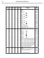
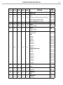
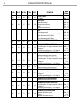
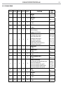
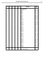
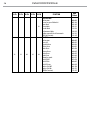
The tables on page 19, 20, 21, 22, 23, 24 indicate the operating modes and related DMX values. As a DMX
interface, the unit has 5-pin XLR contacts.
3.7 DMX ADDRESSING
For operation via a light control unit with DMX512 protocol, simply connect RA2000PROFILE to the con-
troller. The projector has a DMX channel configuration that can be accessed from the control panel. In
order to control RA2000PROFILE with a light control unit, the DMX start address must be set for the first
DMX channel.
If, for example, address 33 is provided on the control unit to control the function of the first one DMX
channel, the start address 33 must be set on the RA2000PROFILE. The other panel functions will be auto-
matically assigned to the following addresses.

13
RA2000PROFILE
3.8 WIRELESS SETTINGS
To enter the Wireless setting mode press the ENTER button until the display shows Connect, then select
Wireless, then press the ENTER button.
• Select the Wireless Receive function using the UP/DOWN buttons, then press the ENTER button.
• To activate the Wireless reception mode, use the UP/DOWN buttons and select the On option.
• Press the ENTER button to confirm the selection.
• Press the LEFT button to go back or wait a few seconds to exit the setup menu.
• NOTE - Once you have performed these steps, you must synchronize with any WiFi unit with which you
want to communicate by pressing the sync button on it. At this point connect the DMX console to the
WiFi unit to open the communication with the RA2000PROFILE.
• To reset the unit, select the Wireless Reset function using the UP/DOWN buttons, press the ENTER button
until the display shows Connect, then select Wireless, then press the ENTER button.
• Select the Wireless Reset function using the UP/DOWN buttons, then press the ENTER button.
• To activate the mode use the UP / DOWN keys and select the Yes option.
• Press the ENTER button to confirm the selection.
• Press the LEFT button to go back or wait a few seconds to exit the setup menu.
To activate the Wireless to DMX function, use the UP / DOWN buttons to press the ENTER button until the
display shows Connect, then select Wireless, then press the ENTER button.
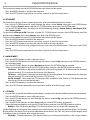
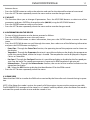
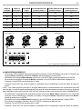
Fig.5 - Example of a DMX 38-channel configuration
DMX Address: 147
DMX Address: 109
DMX Address: 33 DMX Address: 71
. . . . . . . . . . . .
DMX512 Controller
Number of
DMX channels
Start address
(example)
DMX Address
occupied
Next possible start
address for unit No. 1
Next possible start
address for unit No. 2
Next possible start
address for unit No. 3
38 33 33-70 71 109 147
39 33 33-71 72 111 150
40 33 33-72 73 113 153
41 33 33-73 74 115 156
44 33 33-76 77 121 165

RA2000PROFILE
14
To activate the mode use the UP/DOWN buttons and select the Yes option.
• Press the ENTER button to confirm the selection.
• Press the LEFT button to go back or wait a few seconds to exit the setup menu.
3.9 ETHERNET
For the ArtNet settings to be assigned to the unit, refer to the following menu section.
• Press the UP/DOWN button to scroll through the menu, select Connect, then press the ENTER button
access the next Ethernet menu with the UP / DOWN button, then press the ENTER button.
• Use the UP/DOWN buttons to select one of the following settings: Protocol, Universe, Start Channel, IP Ad-
dress, Ethernet to DMX.
To activate the Ethernet to DMX function, use the UP / DOWN buttons to press the ENTER button until the
display shows Connect, then select Ethernet, then press the ENTER button.
To activate the mode use the UP/DOWN buttons and select the Yes option.
• Press the ENTER button to confirm the selection.
• Press the LEFT button to go back or wait a few seconds to exit the setup menu.
• Press the ENTER button to confirm the selection and enter the sub menu.
• Set the desired value for the selected function using the UP/DOWN buttons. Then press the ENTER
button.
• Press the LEFT button to go back or wait a few seconds to exit the setup menu.
3.10 MOVEMENT
• Press the ENTER button to access the main menu.
• Press the UP/DOWN button to scroll through the menu, select Set Up, then press the ENTER button ac-
cess the next menu.
• Press the UP/DOWN button to select Movement and press the ENTER button to proceed.
• Select the proposed option with the UP/DOWN button and press the ENTER button to confirm.
- Pan Reverse - Rotation in the opposite direction of the moving head. NO to deactivate the function
(normal setting); YES to activate the function (Pan Reverse).
- Tilt Reverse - Inclination in the opposite direction of the moving head. NO to deactivate the function
(normal setting), YES to activate the function (Tilt Reverse).
- Pan/Tilt Feedbacks - Rearrange Pan/Tilt position after accidental shift. Select NO for deactivate the
function or YES to activate the function.
• Press the ENTER button to confirm the selection.
• Press the LEFT button repeatedly to exit the menu and to save the changes made.
3.11 SCREEN
• It is possible to modify the following parameters, related to the display, following the same procedure:
• Press the ENTER button to access the main menu.
• Press the UP/DOWN button to scroll through the menu, select Set Up, then press the ENTER button ac-
cess the next menu.
• Press the UP/DOWN button to select Screen and press the ENTER button to proceed.
• Select the proposed option with the UP/DOWN button and press the ENTER button to confirm.
- Backlight - Auto Off display backlight. This function allows you to switch off automatically
the backlighting of the display after a certain time which can be set using the directional keys. To have the
display always on select On or set a value between those shown (10s, 20s, 30s) to turn off the display once
the chosen time has elapsed, after exiting the menu.
- Flip Display - Display orientation. This feature allows you to rotate the display by 180 ° to get a better

15
RA2000PROFILE
view of the display when the unit is hanging upside down. Select YES to activate the function or NO
to deactivate it.
- Warn Cue - Warning of error. Use the arrow keys to select OFF or ON depending on whether or not the
display shows error warnings.
- Key lock - With this function, you can lock the keys on the control panel to prevent, for example, tam-
pering with the settings. If this function is activated, the keys are locked automatically. To disable or
temporarily disable or disable the key lock function, press the keys in the following order to regain
access to the menu commands:
• UP, DOWN, UP, DOWN, ENTER. Select YES to activate the function or NO to deactivate it.
• Press the ENTER button to confirm the selection.
• Press the LEFT key repeatedly to exit the menu and to save the changes made.
3.12 FIXTURE
- Dimmer mode - select this function to choose and simulate different dimming curves:
• Press the ENTER button to access the main menu.
• Press the UP/DOWN button to scroll through the menu, select Set Up, then press the ENTER button ac-
cess the next menu.
• Press the UP/DOWN button to select Fixture and press the ENTER button to proceed.
• Press the UP/DOWN button to scroll through the menu, then select Dimmer mode and press the ENTER
button to confirm.
• Press the UP/DOWN button to select the mode (Off - Dimmer1 - Dimmer2 - Dimmer3), then press the ENTER
button to confirm your choice.
• Press the LEFT button repeatedly to exit the menu and to save the changes made.
- Temperature - Select this function to set the unit of measurement of the temperature shown on the
display:
• Press the ENTER button to access the main menu.
• Press the UP/DOWN button to scroll through the menu, select Set Up, then press the ENTER button to
access the next menu.
• Press the UP/DOWN button to select Fixture and press the ENTER button to proceed.
• Press the UP/DOWN button to scroll through the menu, then select Temperature °C/F and press the ENTER
button to confirm.
• Press the UP / DOWN button to select the Celsius / Fahrenheit measurement unit, then press the ENTER
button to confirm the selection.
• Press the LEFT buttton repeatedly to exit the menu and to save the changes made.
3. 13 FANS MODE
• Select this function to set the fan operating mode:
• Press the ENTER button to access the main menu.
• Press the UP/DOWN button to scroll through the menu, select Set Up, then press the ENTER button ac-
cess the next menu.
• Press the UP/DOWN button to select Fixture and press the ENTER button to proceed.
• Press the UP/DOWN button to scroll through the menu, then select Fans Mode and press the ENTER but-
ton to confirm.
• Press the UP/DOWN button to select the Auto/Silent/High/Off mode, then press the ENTER button to con-
firm your choice.
• Press the LEFT button repeatedly to exit the menu and to save the changes made.

RA2000PROFILE
16
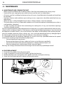
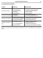
3.14 RED LED MODE
The RA2000PROFILE implements a particular technology where a red led has been added at the center of
the pcb led, in order to increase the CRI and R9 values of the luminous flux, very important values for TV
and theater applications. In addition to the fact that it uses a special CTO filter that always maintains the
above values, the red led means that the CRI value never drops below 90 even when the CTO is inserte
Follow the same procedure:
• Press the ENTER key to access the main menu.
• Press the UP / DOWN button to scroll through the menu, select Set Up, then press the ENTER button to
access the next menu.
• Press the UP / DOWN button to select Fixture and press the ENTER button to proceed.
• Press the UP / DOWN button to scroll through the menu, then select Red Led Mode and press the ENTER
button to confirm.
• Press the UP / DOWN key to select one of the options proposed below, then press the ENTER key to
confirm the choice.
- Off - To deactivate the red led, which will remain off.
- On - To activate the red led, which will remain lit with the possibility of controlling it via the 44-chan-
nel mode.
- Auto - The red led is automatically activated when using the CTO.
• Press the LEFT key several times to exit the menu and to save the changes made.
Amber Shift ON and Amber Shift Off activates and deactivates the halogen lamp simulation mode, when
it is dimmed. For use, Amber Shift must be activated, enter the CTO from 0.3% to 100% (therefore Amber
Shift works from 6000K to 2400K) and dim from 100% to 0% or from 0% to 100%.
The Amber Shift function is possible for the presence of the red LED.
CTO
temperature
Narrow
angle
(Lux)
CT
(K)
Ra R9 R10 DUV
CTO
measurements
(without red leds)
5600K) 26800 5602 93.9 71.7 91.3 0
(3200K) 14100 3204 97.3 89.2 98.2 0
(at 100%) 11900 2531 94.5 90.2 92.9 0
CTO
measurements
(with red leds)
(5600K) 27300 5600 95.4 83.2 93.6 0
(3200K) 14500 3200 96.7 97.4 95.8 0
(at 100%) 12000 2463 93.6 97.1 90 0
3.15 AUTO E MANUAL TEST
Through these menus it is possible to test the functioning of all the functions of the moving head.
3.16 RESET OF THE FUNCTIONS
You can start a preset program to restore the selected function:
• Press the ENTER button to access the main menu.
• Press the UP/DOWN button to scroll through the menu, select Advanced, then press the ENTER button
to enter the next menu.
• Press the UP/DOWN button to select Reset and press the ENTER button to access the next menu.
• Press the UP/DOWN button to scroll through the menu, then select the function you want to reset

17
RA2000PROFILE
between those.
• Press the ENTER button to confirm the selection and wait for the selected function to be restored.
• Press the LEFT button repeatedly to exit the menu and to save the changes made.
3.17 ADJUST
• This function allows you to change all parameters. Press the UP/DOWN buttons to select one of the
parameters and press ENTER to change the value (000-999) using the UP/DOWN buttons.
• Press the ENTER button to confirm your choice.
• Press the LEFT button repeatedly to exit the menu and to save the changes made.
3.18 INFORMATION ON THE DEVICE
• To view all the information on the device, proceed as follows:
• Press the ENTER button to access the main menu.
• Press the UP/DOWN button to select Information, then press the ENTER button to access the next
menu.
• Press the UP/DOWN button to scroll through the menu, then select one of the following information
and press the ENTER button to display it.
- Fixture Time - Through the Fixture Time function, the operating time of the projector can be shown on
the display.
- Temperature - Through the Temperature function it is possible to display on the display the temperature
inside the moving head, where the lamp is located. The temperature can be displayed in degrees
Celsius or Fahrenheit.
- Fans Speed - Through the Fans Speed function it is possible to display on the display the fan speed pre-
sent near the lamp. The speed measurement is expressed in RPM (revolutions per minute).
- Software Version - Through the Software Version function, the version of the installed software can be
viewed on the display.
- UID - Select the UID function to display the identification ID for the RDM control.
• Press the LEFT button repeatedly to exit the menu.
3.19 DMX VIEW
Select the View DMX to visualize the DMX values received by the fixture for each channel during its opera-
tion.
NOTE: if the Motor fast mode is active, the speeds of all the engines increase to the maximum possible.
The RA2000PROFILE manages all the motors in a “smooth” mode by default, when the Motor fast mode is
activated the speeds increase to max and the smooth is lost.

RA2000PROFILE
18
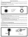
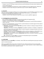
3.20 CONNECTION OF THE DMX LINE
DMX connection employs standard XLR connectors. Use shielded pair-twisted cables with 120Ω imped-
ance and low capacity.
The following diagram shows the connection mode:
Fig.6
DMX - OUTPUT
XLR socket
DMX - INPUT
XLR plug
Pin1 : GND - Shield
Pin2 : - Negative
Pin3 : + Positive
Pin4 : N/C
Pin5 : N/C
ATTENTION
The screened parts of the cable (sleeve) must never be connected to the system’s earth, as this would
cause faulty fixture and controller operation.
Over long runs can be necessary to insert a DMX level matching amplifier.
For those connections the use of balanced microphone cable is not recommended because it cannot
transmit control DMX data reliably.
• Connect the controller DMX input to the DMX output of the first unit.
• Connect the DMX output to the DMX input of the following unit. Connect again the output to the input
of the following unit until all the units are connected in chain.
• When the signal cable has to run longer distance is recommended to insert a DMX termination on the
last unit.
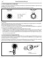
3.21 CONSTRUCTION OF THE DMX TERMINATION
The termination avoids the risk of DMX 512 signals being reflected back along the cable when they reach-
es the end of the line: under certain conditions and with certain cable lengths, this could cause them to
cancel the original signals.
The termination is prepared by soldering a 120Ω 1/4 W resistor between pins 2 and 3 of the 5-pin male XLR
connector, as shown in figure.
Fig.7
Example:
5 pin XLR connector
4
La pagina si sta caricando...
La pagina si sta caricando...
La pagina si sta caricando...
La pagina si sta caricando...
La pagina si sta caricando...
La pagina si sta caricando...
La pagina si sta caricando...
La pagina si sta caricando...
La pagina si sta caricando...
La pagina si sta caricando...
La pagina si sta caricando...
La pagina si sta caricando...
La pagina si sta caricando...
La pagina si sta caricando...
La pagina si sta caricando...
La pagina si sta caricando...
La pagina si sta caricando...
La pagina si sta caricando...
La pagina si sta caricando...
La pagina si sta caricando...
La pagina si sta caricando...
La pagina si sta caricando...
La pagina si sta caricando...
La pagina si sta caricando...
La pagina si sta caricando...
La pagina si sta caricando...
La pagina si sta caricando...
La pagina si sta caricando...
La pagina si sta caricando...
La pagina si sta caricando...
La pagina si sta caricando...
La pagina si sta caricando...
La pagina si sta caricando...
La pagina si sta caricando...
La pagina si sta caricando...
La pagina si sta caricando...
La pagina si sta caricando...
La pagina si sta caricando...
La pagina si sta caricando...
La pagina si sta caricando...
-
 1
1
-
 2
2
-
 3
3
-
 4
4
-
 5
5
-
 6
6
-
 7
7
-
 8
8
-
 9
9
-
 10
10
-
 11
11
-
 12
12
-
 13
13
-
 14
14
-
 15
15
-
 16
16
-
 17
17
-
 18
18
-
 19
19
-
 20
20
-
 21
21
-
 22
22
-
 23
23
-
 24
24
-
 25
25
-
 26
26
-
 27
27
-
 28
28
-
 29
29
-
 30
30
-
 31
31
-
 32
32
-
 33
33
-
 34
34
-
 35
35
-
 36
36
-
 37
37
-
 38
38
-
 39
39
-
 40
40
-
 41
41
-
 42
42
-
 43
43
-
 44
44
-
 45
45
-
 46
46
-
 47
47
-
 48
48
-
 49
49
-
 50
50
-
 51
51
-
 52
52
-
 53
53
-
 54
54
-
 55
55
-
 56
56
-
 57
57
-
 58
58
-
 59
59
-
 60
60


ProLights RA2000PROFILE Manuale utente
- Categoria
- Stroboscopi
- Tipo
- Manuale utente
in altre lingue
- English: ProLights RA2000PROFILE User manual
Documenti correlati
-
ProLights RA2000PROFILE Manuale utente
-
-
-
-
-
-
-
-
-
Altri documenti
-
Cameo OPUS® SP5+ Manuale utente
-
Clay Paky C61700 C61701 Manuale utente
-
PROEL PLSC575ECN Manuale utente
-
-
-
 DTS Synergy 5 Spot Manuale utente
-
SGM IDEA SCANNER 250 Manuale utente
-
-
-
CP Electronics UHS5 Compact Infra Red Commissioning Handset Manuale utente
