BFT Sub BT Manuale utente
- Categoria
- Apriporta da garage
- Tipo
- Manuale utente

SUB BT
D811781 00100_03 17-05-12
ISTRUZIONI DI INSTALLAZIONE
INSTALLATION MANUAL
INSTRUCTIONS D’INSTALLATION
MONTAGEANLEITUNG
INSTRUCCIONES DE INSTALACION
INSTALLATIEVOORSCHRIFTEN
AUTOMAZIONI A PISTONE PER CANCELLI A BATTENTE
PISTON AUTOMATIONS FOR SWING GATES
AUTOMATIONS A PISTON POUR PORTAILS BATTANTS
HYDRAULISCHER DREHTORANTRIEB
AUTOMATIZACIONES A PISTON PARA PORTONES CON BATIENTE
AUTOMATISERINGSSYSTEMEN MET ZUIGER VOOR VLEUGELPOORTEN
SUB BT
Attenzione! Leggere attentamente le “Avvertenze” all’interno! Caution! Read “Warnings” inside carefully! Attention! Veuillez lire attentivement les Avertissements qui se trouvent à l’intérieur! Achtung! Bitte lesen Sie
aufmerksam die „Hinweise“ im Inneren! ¡Atención¡ Leer atentamente las “Advertencias”en el interior! Let op! Lees de “Waarschuwingen”tigre aan de binnenkant zorgvuldig!
8
027908 387745

B
A
A
B
A
B
0,75
0,75
3x2,5 mm
2
3x2,5 mm
2
5x0,75 mm
2
5x0,75 mm
2
2x0,75 mm
2
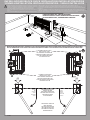
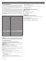
PREDISPOSIZIONE TUBI, TUBE ARRANGEMENT,
PRÉDISPOSITION DES TUYAUX, VORBEREITUNG DER LEITUNGEN,
DISPOSICIÓN DE TUBOS, VOORBEREIDING LEIDINGEN.
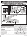
REGOLAZIONE FINECORSA E BATTUTE D’ARRESTO / ADJUSTING THE TRAVEL LIMITS AND STOPS/ RÉGLAGE DES FINS DE COURSE ET DES BUTÉES D’ARRÊT/
EINSTELLUNG ENDANSCHLAG UND SCHLIESSPUNKTE/ REGULACIÓN FINALES DE CARRERA Y TOPES DE PARADA/AFSTELLING EINDAANSLAGEN EN STOPAANSLAGEN
POSIZIONE DI CHIUSURA
CLOSED POSITION
POSITION DE FERMETURE
POSITION BEIM SCHLIESSEN
POSICIÓN DE CIERRE
SLUITINGSPOSITIE
sinistra
left
gauche
links
izquierda
links
destra
right
droite
rechts
derecha
rechts
FINECORSA IN APERTURA
OPENING LIMIT STOP
FIN DE COURSE D’OUVERTURE
ENDANSCHLAG BEIM ÖFFNEN
FINAL DE CARRERA DE APERTURA
OPENINGSAANSLAG
FINECORSA DI CHIUSURA
CLOSING LIMIT STOP
FIN DE COURSE DE FERMETURE
ENDANSCHLAG BEIM SCHLIESSEN
FINAL DE CARRERA DE CIERRE
SLUITINGSAANSLAG
POSIZIONE DI APERTURA
OPEN POSITION
POSITION D’OUVERTURE
POSITION BEIM ÖFFNEN
POSICIÓN DE APERTURA
OPENINGSPOSITIE
INSTALLAZIONE VELOCE-QUICK INSTALLATION-INSTALLATION RAPIDE
SCHNELLINSTALLATION-INSTALACIÓN RÁPIDA - SNELLE INSTALLATIE
a) Prima di iniziare con l’installazione bisogna leggere le avvertenze.
a) Before commencing installation, make sure you read the warnings.
a) Avant de commencer l’installation lisez les avertissements.
a) Vor der Installation müssen die Hinweise gelesen werden.
a) Antes de comenzar con la instalación es necesario leer las adver-
tencias.
a) Voor met de installatie te beginnen moet u de waarschuwingen lezen.
b) Oltre alle gure, bisogna seguire le indicazioni date nel paragrafo corrispondente a pag.10
b) In addition to the gures, you must follow the instructions given in the relevant section on page 12
b) Suivez non seulement les gures mais aussi les indications données dans le paragraphe correspondant à
la page 14
b) Außer den Abbildungen müssen die Angaben im entsprechenden Abschnitt auf Seite 16 befolgt werden
b) Además de las guras, es necesario seguir las indicaciones dadas en el apartado correspondiente en pág. 18
b) Volg niet alleen de guren, maar ook de aanwijzingen die in de paragraaf op pag. 20 staan
2 - SUB BT
D811781 00100_03

ITALIANO ENGLISH
FRANÇAIS ESPAÑOL
NEDERLANDS
DEUTSCH
B1
2
1
4
A
B
3
5
6
7
8
OPEN
( - )
( - )
( + )
( + )
32°
32°
3°
32°
93°
58°
61°
32°
88°
58°
120°
2°
max 1.5 Nm
max 1.5 Nm
Valvola di servizio/Service valve
Vanne de service/ Serviceventil
Válvula de servicio/ Serviceklep
Perno / pin/ Pivot/ Bolzen/ Perno/ Pen
“A”
Perno / pin/ Pivot/ Bolzen/
Perno/ Pen “B”
sinistra
left
gauche
links
izquierda
links
sinistra
left
gauche
links
izquierda
links
sinistra
left
gauche
links
izquierda
links
destra
right
droite
rechts
derecha
rechts
destra
right
droite
rechts
derecha
rechts
destra
right
droite
rechts
derecha
rechts
SUB BT -
3
D811781 00100_03

G
1
3
2
5
5
G
G
4
5
E F
DC
M
P
D
MCP
FCM
V1
OIL
353
260
151
*Bianco (SW)
*Bianco **Rosso ***Nero
White Red Black
Blanc Rouge Noir
Weiß Rot Nero
Blanco Rojo Negro
Wit Rood Zwart
**Rosso (MOT +)
***Nero (MOT -)
*oil level / niveau d’huile/ Ölstand/ nivel aceite/ oliepeil
livello olio *
4 - SUB BT
D811781 00100_03

ENGLISH
INSTALLER WARNINGS
Anything that is not explicitly provided for in the installation ma-
nual is not allowed. The operator’s proper operation can only be
guaranteed if the information given is complied with. The Firm shall
not be answerable for damage caused by failure to comply with the
instructions featured herein.
While we will not alter the product’s essential features, the Firm re-
serves the right, at any time, to make those changes deemed oppor-
tune to improve the product from a technical, design or commercial
point of view, and will not be required to update this publication
accordingly.
WARNING! Important safety instructions. Carefully read and comply with
all the warnings and instructions that come with the product as incorrect
installation can cause injury to people and animals and damage to property.
The warnings and instructions give important information regarding safety,
installation, use and maintenance. Keep hold of instructions so that you can
attach them to the technical le and keep them handy for future reference.
GENERAL SAFETY
This product has been designed and built solely for the purpose indicated herein.
Uses other than those indicated herein might cause damage to the product and
create a hazard.
- The units making up the machine and its installation must meet the requirements
of the following European Directives, where applicable: 2004/108/EC, 2006/95/
EC, 2006/42/EC, 89/106/EC, 99/05/EC and later amendments. For all countries
outside the EEC, it is advisable t
o comply with the standards mentioned, in ad-
dition to any national standards in force, to achieve a good level of safety.
- The Manufacturer of this product (hereinafter referred to as the “Firm”) disclaims
all responsibility resulting from improper use or any use other than that for
which the product has been designed, as indicated herein, as well as for failure
to apply Good Practice in the construction of entry systems (doors, gates, etc.)
and for deformation that could occur during use.
- Before installing the product, make all structural changes required to produce
safety gaps and to provide protection from or isolate all crushing, shearing and
dragging hazard areas and danger zones in general in accordance with the
provisions of standards EN 12604 and 12453 or any local installation standards.
Check that the existing structure meets the necessary strength and stability
requirements.
- Before commencing installation, check the product for damage.
- The Firm is not responsible for failure to apply Good Practice in the construction
and maintenance of the doors, gates, etc. to be motorized, or for deformation
that might occur during use.
- Make sure the stated temperature range is compatible with the site in which the
automated system is due to be installed.
- Do not install this product in an explosive atmosphere: the presence of ammable
fumes or gas constitutes a serious safety hazard.
- Disconnect the electricity supply before performing any work on the syst
em.
A
lso disconnect buer batteries, if any are connected.
- Before connecting the power supply, make sure the product’s ratings match the
mains ratings and that a suitable residual current circuit breaker and overcurrent
protection device have been installed upline from the electrical system. Hav
e
the aut
omated system’s mains power supply tted with a switch or omnipolar
thermal-magnetic circuit breaker with a contact separation that meets code
requirements.
- Make sure that upline from the mains power supply there is a residual current
circuit breaker that trips at no more than 0.03A as well as any other equipment
required by code.
- Make sure the earth system has been installed correctly: earth all the metal parts
belonging to the entry system (doors, gates, etc.) and all parts of the syst
em
f
eaturing an earth terminal.
- Installation must be carried out using safety devices and controls that meet
standards EN 12978 and EN 12453.
- Impact forces can be reduced by using deformable edges.
- In the event impact forces exceed the values laid down by the relevant standards,
apply electro-sensitive or pressure-sensitive devices.
- Apply all safety devices (photocells, safety edges, etc.) required to keep the
area free of impact, crushing, dragging and shearing hazards. Bear in mind the
standards and directives in force, Good Practice criteria, intended use, the instal-
lation environment, the operating logic of the system and forces generated by
the automated system.
- Apply all signs required by current code to identify hazardous areas (r
esidual
r
isks). All installations must be visibly identied in compliance with the provisions
of standard EN 13241-1.
- Once installation is complete, apply a nameplate featuring the door/gate’s data.
- This product cannot be installed on leaves incorporating doors (unless the motor
can be activated only when the door is closed).
- If the automated system is installed at a height of less than 2.5 m or is accessible,
the electrical and mechanical parts must be suitably protected.
- Install any xed controls in a position where they will not cause a hazard, away
from moving parts. More specically, hold-to-run controls must be positioned
within direct sight of the part being controlled and, unless they are key operated,
must be installed at a height of at least 1.5 m and in a place where they cannot
be reached by the public.
- Apply at least one warning light (ashing ligh
t) in a visible position, and also
a
ttach a Warning sign to the structure.
- Attach a label near the operating device, in a permanent fashion, with informa-
tion on how to operate the automated system’s manual release.
- Make sure that, during operation, mechanical risks are avoided or relevant
protective measures taken and, more specically, that nothing can be banged,
crushed, caught or cut between the part being operated and surrounding parts.
- Once installation is complete, make sure the motor automation settings are
correct and that the safety and release systems are working properly.
- Only use original spare parts for any maintenance or repair work. The Firm dis-
claims all responsibility for the correct operation and safety of the automated
sy
stem if parts from other manufacturers are used.
- Do not make any modications to the automated system’s components unless
explicitly authorized by the Firm.
- Instruct the system’s user on what residual risks may be encountered
, on the
c
ontrol systems that have been applied and on how to open the system manu-
ally in an emergency. give the user guide to the end user.
- Dispose of packaging materials (plastic, cardboard, polystyrene, etc.) in accord-
ance with the provisions of the laws in force. Keep nylon bags and polystyrene
out of reach of children.
WIRING
WARNING! For connection to the mains power supply, use: a multicore cable with
a cross-sectional area of at least 5x1.5mm
2
or 4x1.5mm
2
when dealing with three-
phase power supplies or 3x1.5mm
2
for single-phase supplies (by way of example,
type H05 VV-F cable can be used with a cross-sectional area of 4x1.5mm
2
). To con-
nect auxiliary equipment, use wires with a cross-sectional area of at least 0.5 mm
2
.
- Only use pushbuttons with a capacity of 10A-250V or more.
- Wires must be secured with additional fastening near the terminals (for example,
using cable clamps) in order to keep live parts well separated from safety extra
low voltage parts.
- During installation, the power cable must be stripped to allow the earth wire
to be connected to the relevant terminal, while leaving the live wires as short
as possible. The earth wire must be the last to be pulled taut in the event the
cable’s fastening device comes loose.
WARNING! safety extra low voltage wires must be kept physically separate from
low voltage wires.
Only qualied personnel (professional installer) should be allowed to access
live parts.
CHECKING THE AUTOMATED SYSTEM AND MAINTENANCE
Before the automated system is nally put into operation, and during maintenance
work, perform the following checks meticulously:
- Make sure all components are fastened securely.
- Check starting and stopping operations in the case of manual control.
- Check the logic for normal or personalized operation.
- For sliding gates only: check that the rack and pinion mesh correctly with 2 mm
of play along the full length of the rack; keep the track the gate slides on clean
and free of debris at all times.
- For sliding gates and doors only: make sure the gate’s running track is straight
and horizontal and that the wheels are strong enough to take the weight of the
gate.
- For cantilever sliding gates only: make sure there is no dipping or swinging
during operation.
- For swing gates only: make sure the leaves’ axis of rotation is perfectly vertical.
- Check that all safety devices (photocells, safety edges, etc.) are working properly
and that the anti-crush safety device is set correctly, making sure that the force
of impact measured at the points provided for by standard EN 12445 is low
er
than the v
alue laid down by standard EN 12453.
- Impact forces can be reduced by using deformable edges.
- Make sure that the emergency operation works, where this feature is provided.
- Check opening and closing operations with the control devices applied.
- Check that electrical connections and cabling are intact, making extra sure that
insulating sheaths and cable glands are undamaged.
- While performing maintenance, clean the photocells’ optics.
- When the automated system is out of service for any length of time, activate the
emergency release (see “EMERGENCY OPERATION” section) so that the operated
part is made idle, thus allowing the gate to be opened and closed manually.
-
If the power cord is damaged, it must be replaced by the manufacturer or their
t
echnical assistance department or other such qualied person to avoid any risk .
- If “D” type devices are installed (as dened by EN12453), connect in unveried
mode, foresee mandatory maintenance at least every six months
WARNING!
Remember that the drive is designed to make the gate/door easier t
o use and
will not solv
e problems as a result of defective or poorly performed installation
or lack of maintenance
SCRAPPING
Materials must be disposed of in accordance with the regulations in force. There
are no particular hazards or risks involved in scrapping the automated system. For
the purpose of recycling, it is best to separate dismantled parts into like materials
(electrical parts - copper - aluminium - plastic - etc.).
DISMANTLING
If the automated system is being dismantled in order to be reassembled at another
site, you are required to:
- Cut o the power and disconnect the whole electrical system.
- Remove the actuator from the base it is mounted on.
- Remove all the installation’s components.
- See to the replacement of any components that cannot be removed or happen
to be damaged.
AVVERTENZE PER L’INSTALLATORE D811766_06
SUB BT - 7
D811781 00100_03

INSTALLATION MANUAL
1) GENERAL INFORMATION
The SUB BT hydraulic actuator is ideal for in-ground under-hinge appli-
cations. It is a brilliant solution to the problem of making the automated
system aesthetically unobtrusive. The SUB BT actuator comes as a water-
proof self-contained unit incorporating the hydraulic power pack-jack,
which means it can be installed fully under ground without the need
for any hydraulic connections.
The gate is kept closed by a hydraulic locking feature or by a solenoid
lock. The actuator features soft-closing so that the gate opens and
closes without clanging; operating force is adjusted automatically and
extremely accurately by means of the control unit’s electronic control.
The actuator features built-in mechanical limit stops that can be adju-
sted over the last 32 degrees of the gate’s opening and closing travel to
make the installer’s job easier and also avoid having to install external
mechanical stops.
2) TECHNICAL SPECIFICATIONS
Power supply (*) 24V
Max. power input 300W
Max. pressure 30 bar
Pump delivery rate 0,9 l/min.
Max. torque 400 Nm
Type of use very intensive
Type of locking Hydraulic
Ambient temperature range -20°C to 60°C
Impact reaction electronic clutch (with control panel)
Manual operation release key
Protection rating IP 67
Actuator weight 16 kg
Max. leaf weight 800 kg.
Max. leaf length
2.5m (when dealing with leaves over 2 m long,
use the solenoid lock )(*1)
Max. opening angle 120°
Angular velocity 9°/s
Overall dimensions Fig. D
Oil Idrolux Winter
(*) Special supply voltages to order.
(*1) CAUTION!!! for correct operation, use the floor-mounted
stops.
CAUTION!!! If you are using two solenoid locks in the installation,
you will need to run the second lock o a separate power supply.
3) TUBE ARRANGEMENT FIG. A
4) ADJUSTING THE TRAVEL LIMITS AND STOPS FIG. B:
Warning! Do not attempt to move the leaf using the limit stop
adjustment screw.
WARNING! Make sure that the leaf approaches the opening and
closing travel limits at slowed speed.
Turning pin “A” (- direction) --> leaf angle decreases.
Turning pin “B” (+ direction) --> leaf angle increases.
The pin can be turned manually or with a battery-powered screwdriver
set to 1.5 Nm.
13 turns of pin “A” = limit stop moved by 1.5 mm ≈ 3° Leaf (opening-
closing). Total FCM1 movement: 15 mm ≈ 32°.
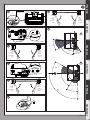
FIG. B1:
- Release the operator by opening the service valve (Ref. 1).
- Close the leaf (manually) (Ref. 2).
- Turn the closing limit stop pin “A” as far as it will go in the (-) direction
(Ref. 3).
- Sample adjustments (Ref. 4):
- up to 120° (Ref. A)
- up to 93° (Ref. B).
- Open the leaf manually (to the desired position) (Ref. 5).
-
Turn the opening limit stop pin “B” as far as it will go in the (-) direction
(Ref. 6).
- Open and close both gate leaves to check that the limit stops are
adjusted correctly.
- Close the leaf (manually) (Ref. 7).
- Lock the operator again by closing the service valve (Ref. 8)
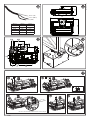
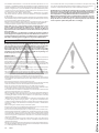
5) POWER CABLE FIG. C
6) MAIN PARTS OF AUTOMATED SYSTEM FIG. E
FCM: motor limit stop
MCP: jack, rack, pinion
M: motor
P: hydraulically driven lobe pump
D: control valve assembly
V1: service valve
MAINTENANCE:
7) LUBRICATING THE SERVICE VALVE Fig. F
Caution: this operation needs to be performed every 12 months.
7.1) TOPPING UP OIL FIG. G
Caution: an oil change is recommended every 5 years.
8) MANUAL OPENING (See USER GUIDE -FIG. 1-).
8 - SUB BT
D811781 00100_03

MANUALE D’USO: MANOVRA DI EMERGENZA / USER GUIDE:EMERGENCY OPERATION-
MANUEL D’UTILISATION: DE LA MANŒUVRE D’URGENCE
/ BEDIENUNGSHANDBUCH: NOTFALLMANÖVER-
MANUAL DE USO: MANIOBRA DE EMERGENCIA / GEBRUIKERSHANDLEIDING: NOODMANOEUVRE
ATTIVAZIONE SBLOCCO DI EMERGENZA / ACTIVATING EMERGENCY RELEASE.
ACTIVATION DU DÉVERROUILLAGE D’URGENCE
/ AKTIVIERUNG NOTFALLENTSPERRUNG.
ACTIVACIÓN DEL DESBLOQUEO DE EMERGENCIA / ACTIVERING NOOD-DEBLOKKERING.
Max. 90°
ON
OFF
ON
1
2
3
FIG.1
AVVERTENZE PER L’UTILIZZATORE ( I )
ATTENZIONE! Importanti istruzioni di sicurezza. Leggere e seguire attenta-
mente le Avvertenze e le Istruzioni che accompagnano il prodotto poiché
un uso improprio può causare danni a persone, animali o cose. Conservare
le istruzioni per consultazioni future e trasmetterle ad eventuali subentranti
nell’uso dell’impianto.
Questo prodotto dovrà essere destinato solo all’uso per il quale è stato
espressamente installato. Ogni altro uso è da considerarsi improprio e
quindi pericoloso. Il costruttore non può essere considerato responsabile
per eventuali danni causati da usi impropri, erronei e irragionevoli.
SICUREZZA GENERALE
Nel ringraziarVi per la preferenza accordata a questo prodotto, la Ditta è certa
che da esso otterrete le prestazioni necessarie al Vostro uso.
Questo prodotto risponde alle norme riconosciute della tecnica e della disposi-
zioni relative alla sicurezza se correttamente installato da personale qualicato
ed esperto (installatore professionale).
L’automazione, se installata ed utilizzata correttamente, soddisfa gli standard di
sicurezza nell’uso. Tuttavia è opportuno osservare alcune regole di comportamento
per evitare inconvenienti accidentali:
- Tenere bambini, persone e cose fuori dal raggio d’azione dell’automazione, in
particolare durante il movimento.
- Non permettere a bambini di giocare o sostare nel raggio di azione
dell’automazione.
- Questa automazione non è destinata all’uso da parte di bambini o da parte di
persone con ridotte capacità mentali, siche e sensoriali, o persone che manca-
no di conoscenze adeguate a meno che esse non abbiano potuto beneciare,
attraverso l’intermediazione di una persona responsabile della loro sicurezza, di
una sorveglianza o di istruzioni riguardanti l’uso dell’apparecchio.
- I bambini devono essere sorvegliati per sincerarsi che non giochino con
l’apparecchio. Non permettere ai bambini di giocare con i controlli ssi. Tenere
i telecomandi lontani dai bambini.
-
Evitare di operare in prossimità delle cerniere o organi meccanici in movimento.
-
Non contrastare il movimento dell’anta e non tentare di aprire manualmente la
porta se non è stato sbloccato l’attuatore con l’apposita manopola di sblocco.
- Non entrare nel raggio di azione della porta o cancello motorizzati durante il
loro movimento.
- Non lasciare radiocomandi o altri dispositivi di comando alla portata dei bambini
onde evitare azionamenti involontari.
- L’attivazione dello sblocco manuale potrebbe causare movimenti incontrollati
della porta se in presenza di guasti meccanici o di condizioni di squilibrio.
- In caso di apritapparelle: sorvegliare la tapparella in movimento e tenere lontano
le persone nché non è completamente chiusa. Porre cura quando si aziona lo
sblocco se presente, poiché una tapparella aperta potrebbe cadere rapidamente
in presenza di usura o rotture.
-
La rottura o l’usura di organi meccanici della porta (parte guidata), quali ad esempio
cavi, molle, supporti, cardini, guide.. potrebbe generare pericoli. Far controllare
periodicamente l’impianto da personale qualicato ed esperto (installatore profes-
sionale) secondo quanto indicato dall’installatore o dal costruttore della porta.
- Per ogni operazione di pulizia esterna, togliere l’alimentazione di rete.
- Tenere pulite le ottiche delle fotocellule ed i dispositivi di segnalazione luminosa.
Controllare che rami ed arbusti non disturbino i dispositivi di sicurezza.
SUB BT -
17
D811781 00100_03

- Non utilizzare l’automatismo se necessita di interventi di riparazione. In caso
di guasto o di malfunzionamento dell’automazione, togliere l’alimentazione di
rete sull’automazione, astenersi da qualsiasi tentativo di riparazione o intervento
diretto e rivolgersi solo a personale qualicato ed esperto (installatore profes-
sionale) per la necessaria riparazione o manutenzione. Per consentire l’accesso,
attivare lo sblocco di emergenza (se presente).
-
Per qualsiasi intervento diretto sull’automazione o sull’impianto non previsto
dal presente manuale, avvalersi di personale qualicato ed esperto (installatore
professionale).
- Con frequenza almeno annuale far vericare l’integrità e il corretto funzionamento
dell’automazione da personale qualicato ed esperto (installatore professionale),
in particolare di tutti i dispositivi di sicurezza.
- Gli interventi d’installazione, manutenzione e riparazione devono essere docu-
mentati e la relativa documentazione tenuta a disposizione dell’utilizzatore.
- Il mancato rispetto di quanto sopra può creare situazioni di pericolo.
Tutto quello che non è espressamente previsto nel manuale d’uso, non è
permesso. ll buon funzionamento dell’operatore è garantito solo se ven-
gono rispettate le prescrizioni riportate in questo manuale. La Ditta non
risponde dei danni causati dall’inosservanza delle indicazioni riportate in
questo manuale.
Lasciando inalterate le caratteristiche essenziali del prodotto, la Ditta si
riserva di apportare in qualunque momento le modiche che essa ritiene con-
venienti per migliorare tecnicamente, costruttivamente e commercialmente
il prodotto, senza impegnarsi ad aggiornare la presente pubblicazione.
USER WARNINGS (GB)
WARNING! Important safety instructions. Carefully read and comply with
the Warnings and Instructions that come with the product as improper use
can cause injury to people and animals and damage to property. Keep the
instructions for future reference and hand them on to any new users.
This product is meant to be used only for the purpose for which it was expli-
citly installed. Any other use constitutes improper use and, consequently,
is hazardous. The manufacturer cannot be held liable for any damage as a
result of improper, incorrect or unreasonable use.
GENERAL SAFETY
Thank you for choosing this product. The Firm is condent that its performance
will meet your operating needs.
This product meets recognized technical standards and complies with safety provisions
when installed correctly by qualied, expert personnel (professional installer).
If installed and used correctly, the automated system will meet operating safety
standards. Nonetheless, it is advisable to observe certain rules of behaviour so
that accidental problems can be avoided:
- Keep adults, children and property out of range of the automated system,
especially while it is moving.
- Do not allow children to play or stand within range of the automated system.
- This automated system is not meant for use by children or by people with impai-
red mental, physical or sensory capacities, or people who do not have suitable
knowledge, unless a person who is responsible for their safety provides them
with necessary supervision or instructions on how to use the device.
- Children must be supervised to ensure they do not play with the device. Do not
allow children to play with the xed controls. Keep remote controls out of reach
of children.
- Do not work near hinges or moving mechanical parts.
- Do not hinder the leaf ’s movement and do not attempt to open the door manually
unless the actuator has been released with the relevant release knob.
- Keep out of range of the motorized door or gate while they are moving.
- Keep remote controls or other control devices out of reach of children in order
to avoid the automated system being operated inadvertently.
- The manual release’s activation could result in uncontrolled door movements if
there are mechanical faults or loss of balance.
- When using roller shutter openers: keep an eye on the roller shutter while it is
moving and keep people away until it has closed completely. Exercise care when
activating the release, if such a device is tted, as an open shutter could drop
quickly in the event of wear or breakage.
- The breakage or wear of any mechanical parts of the door (operated part), such
as cables, springs, supports, hinges, guides…, may generate a hazard. Have the
system checked by qualied, expert personnel (professional installer) at regular
intervals according to the instructions issued by the installer or manufacturer
of the door.
- When cleaning the outside, always cut o mains power.
- Keep the photocells’ optics and illuminating indicator devices clean. Check that
no branches or shrubs interfere with the safety devices.
- Do not use the automated system if it is in need of repair. In the event the auto-
mated system breaks down or malfunctions, cut o mains power to the system;
do not attempt to repair or perform any other work to rectify the fault yourself
and instead call in qualied, expert personnel (professional installer) to perform
the necessary repairs or maintenance. To allow access, activate the emergency
release (where tted).
- If any part of the automated system requires direct work of any kind that is
not contemplated herein, employ the services of qualied, expert personnel
(professional installer).
- At least once a year, have the automated system, and especially all safety devices,
checked by qualied, expert personnel (professional installer) to make sure that
it is undamaged and working properly.
- A record must be made of any installation, maintenance and repair work and
the relevant documentation kept and made available to the user on request.
- Failure to comply with the above may result in hazardous situations.
Anything that is not explicitly provided for in the user guide is not allowed.
The operator’s proper operation can only be guaranteed if the instructions
given herein are complied with. The Firm shall not be answerable for damage
caused by failure to comply with the instructions featured herein.
While we will not alter the product’s essential features, the Firm reserves the
right, at any time, to make those changes deemed opportune to improve
the product from a technical, design or commercial point of view, and will
not be required to update this publication accordingly.
18 - SUB BT
D811781 00100_03

-
 1
1
-
 2
2
-
 3
3
-
 4
4
-
 5
5
-
 6
6
-
 7
7
-
 8
8
-
 9
9


BFT Sub BT Manuale utente
- Categoria
- Apriporta da garage
- Tipo
- Manuale utente
in altre lingue
- English: BFT Sub BT User manual
Documenti correlati
-
BFT Ares Ultra BT A Manuale utente
-
-
-
-
-
-
-
-
-