BFT Ares Ultra BT A Manuale utente
- Categoria
- Apriporta da garage
- Tipo
- Manuale utente

ISTRUZIONI D’USO E DI INSTALLAZIONE
INSTALLATION AND USER’S MANUAL
INSTRUCTIONS D’UTILISATION ET D’INSTALLATION
INSTALLATIONS-UND GEBRAUCHSANLEITUNG
INSTRUCCIONES DE USO Y DE INSTALACION
INSTALLATIEVOORSCHRIFTEN
ATTUATORE PER CANCELLI SCORREVOLI A CREMAGLIERA
ACTUATOR FOR RACK SLIDING GATES
ACTIONNEUR POUR PORTAILS COULISSANTS A CREMAILLERE
ANTRIEB FÜR ZAHNSTANGEN-SCHIEBETORE
SERVOMOTOR PARA CANCELAS CORREDERAS DE CREMALLERA
ACTUATOR VOOR SCHUIFHEKKEN MET TANDHEUGEL
Attenzione! Leggere attentamente le “Avvertenze” all’interno! Caution! Read “Warnings” inside carefully! Attention! Veuillez lire attentivement les Avertissements qui se trouvent à l’intérieur!
Achtung! Bitte lesen Sie aufmerksam die „Hinweise“ im Inneren! ¡Atención¡ Leer atentamente las “Advertencias”en el interior! Let op! Lees de “Waarschuwingen” aan de binnenkant zorgvuldig!
D812201 00100_03 14-04-16
ARES ULTRA BT A 1000
ARES ULTRA BT A 1500
ULTRA

INSTALLAZIONE VELOCE-QUICK INSTALLATION-INSTALLATION RAPIDE
SCHNELLINSTALLATION-INSTALACIÓN RÁPIDA - SNELLE INSTALLATIE
2x0.75mm
2
3x1.5mm
2
RG58
3x1.5mm
2
3x1.5mm
2
5x0,75mm
2
2x1.5mm
2
Y
Y
A
C
C1
E
D1D
22mm + “X”
> 25mm
B
> 10mm
1
2
MAX 7 mm
MAGNETO
3x0.5mm
2
1
2 3
PREDISPOSIZIONE TUBI, TUBE ARRANGEMENT
PRÉDISPOSITION DES TUYAUX, VORBEREITUNG DER LEITUNGEN,
DISPOSICIÓN DE TUBOS, VOORBEREIDING LEIDINGEN.
MONTAGGIO ACCESSORI TRASMISSIONE, MOUNTING DRIVE ACCESSORIES, MONTAGE ACCESSOIRES TRANSMISSION,
MONTAGE ANTRIEBSZUBEHÖR, MONTAJE DE ACCESORIOS TRANSMISIÓN, MONTAGE ACCESSOIRES OVERBRENGING.
FISSAGGIO STAFFE FINECORSA (DX E SX),
FASTENING LIMIT SWITCH BRACKETS (RH/LH),
FIXATION ÉTRIERS FIN DE COURSE (DRT ET GCH),
BEFESTIGUNG BÜGEL ANSCHLÄGE (RECHTS UND LINKS),
FIJACIÓN ABRAZADERAS FINAL DE CARRERA (DER. E IZQ.),
BEVESTIGING STANGEN AANSLAG (RECHTS EN LINKS).
MONTAGGIO MOTORE
MOUNTING THE MOTOR
MONTAGE MOTEUR
MONTAGE MOTOR
MONTAJE DEL MOTOR
MONTAGE MOTOR
PREDISPOSIZIONE FISSAGGIO MOTORE, PREPARATION FOR MOTOR MOUNTING,
AMÉNAGEMENT FIXATION MOTEUR, VORBEREITUNG MOTORBEFESTIGUNG,
DISPOSICIÓN FIJACIÓN DEL MOTOR, VOORBEREIDING BEVESTIGING MOTOR.
“X”=
Cremagliera, Rack,
Crémaillère, Zahnstange
Cremallera, Tandheugel
2 - ARES ULTRA BT A 1000 - ARES ULTRA BT A 1500
D812201 00100_03

ENGLISH FRANÇAIS ESPAÑOL
NEDERLANDS
DEUTSCHITALIANO
F
AUX 3 = 0
AUX 3 = 2
AUX 3 = 3
AUX 3 = 4
AUX 3 = 5
AUX 3 = 6
AUX 3 = 7
AUX 3 = 8
AUX 3 = 9
AUX 3 = 10
AUX 0 = 0
AUX 0 = 2
AUX 0 = 3
AUX 0 = 4
AUX 0 = 5
AUX 0 = 7
AUX 0 = 8
AUX 0 = 9
AUX 0 = 10
AUX 0 = 6 AUX 3 = 1
21
24 V
SCA
!
24V
25W
20 21
AUX0
(MAX 1A)
20 21
26 27
!
F3 1,25A T
F1 1,6 AT (220-230V)
F1 3,15 AT (120V)
10L N 11 20 21 26 27 50 51 52 60 61 62 70 71 72 73 74 75
L
N
M1
+
-
AUX 3
(MAX 24V 1A)
24V ~ (-)
24V ~ (+)
24 VSafe
COM
IC 1
IC 2
NO
NO
SAFE 1
STOP
COM
FAULT 1
SAFE 2
FAULT 2
NC
NC
NC
S1
S2
S3
+
-
OK
24V~
JP3
24V
2
1
TX1
2
1
RX1
4
5
3
SAFE 1 = 0
24V
!
AUX 0
(MAX 1A)
24V
26 27 50 51
50 51
70 72
OPEN
CLOSE
S1
S2
+
S1
+
-
S2
-
X1
X1 X1
X1
OPEN
CLOSE STOP
STOP
**
G
Display + tasti programmazione,
Display plus programming keys,
Acheur et touches de programmation,
Display und Programmierungstasten,
Pantalla más botones de programación,
Display meerdere toetsen programmeur.
Connettore necorsa
Limit switch connector
Connecteur de n de course
Steckverbindung Endschalter
Conector nal de carrera
Connector eindaanslag
Connettore programmatore palmare,
Palmtop programmer connector,
Connecteur programmateur de poche,
Steckverbinder Palmtop-Programmierer,
Conector del programador de bolsillo,
Connector programmeerbare palmtop.
Sicurezze
Safety devices
Sécurités
Sicherheitsvorrichtungen
Dispositivos de seguridad
Veiligheden
Comandi / Commands
Commandes/Bedienelemente
Mandos/ Commando’s
Motore / Motor / moteur
Motor /Eindaanslag/Encoder
Alimentazione / Power supply
Alimentation / Stromversorgung
Alimentación /Voeding
Collegamento di 1 coppia di fotocellule non vericate,
Connection of 1 pair of non-tested photocells,
Connexion 1 paire photocellules no vériées,
Anschluss von einem Paar nicht überprüften Fotozellen,
Conexión de 1 par fotocélulas no comprobadas,
Aansluiting van 1 paar fotocellen anders dan “trusted device”.
**Con logica inversione direzione di apertura = 000 (DIR=DX) / **With reverse logic, opening direction = 000 (DIR=right)
** Avec logique inversion direction d’ouverture = 000 (DIR=DRT) / **Mit Inversionslogik Ö nungsrichtung = 000 (DIR=rechts)
**Con lógica inversión dirección de apertura = 000 (DIR=DER) / **Met logica omkering openingsrichting = 000 (DIR=R)
Alimentazione accessori
Accessories power supply
Alimentation des accessoires
Stromversorgung Zubehör
Alimentación accesorios
Voeding accessoires
Connettore scheda opzionale,
Optional board connector,
Connecteur carte facultative,
Steckverbinder Zusatzkarte,
Conector de la tarjeta opcional,
Connector optionele kaart.
AUX
ARES ULTRA BT A 1000 - ARES ULTRA BT A 1500 - 3
D812201 00100_03

ENGLISH FRANÇAIS ESPAÑOL
NEDERLANDS
DEUTSCHITALIANO
language
dir
ITA
fra
deu
eng
esp
lh
rh
AR
preset
e
hidden button
release O 01
re otes
sr
ac
sc
ind
end
ar: automatic operation,
residential
sr: semiautomatic operation,
residential
ac: automatic operation,
commercial
Sc: semiautomatic operation,
commercial
Ind:dead man operation
lh
rh
desidered button
: motor installed on the left
: motor installed on the right
autoset
. . . . . .
o o
AUTO OPEN
AUTO CLOSE
MIN 1 - MAX 3
Exit Menù
Conrm/Switch
on display
Scroll up
Scroll down
SIMPLIFIED MENU (FIG.1)
x1
0---
10--
150- 1520 ok
*** Password entry.
Request with Protection Level logic set to 1, 2, 3, 4
***
PRESET
DEFAULT
ar sr ac sc ind
PARAMETERS
LOGIC
TCA 0 1 0 1 0 0
Step-by-step movement 0 1 0 1 0 0
Pre-alarm 0 0 0 1 1 0
Deadman 0 0 0 0 0 1
Block pulses during opening 0 0 0 1 1 0
ARES ULTRA BT A 1000 - ARES ULTRA BT A 1500 - 5
D812201 00100_03

E
O
UNIDA
P
F3
F1
10L N 11 20 21 26 27 50 51 52 60 61 62 70 71 72 73 74 75
S1
S2
S3
+
-
OK
F3
F1
10L N 11 20 21 26 27 50 51 52 60 61 62 70 71 72 73 74 75
S1
S2
S3
+
-
OK
TX1 (PHOT)
RX1 (PHOT)
CC1
(BAR)
CC2
(BAR)
TX2 (PHOT)
RX2 (PHOT)
M2
SLAVE
M1
MASTER
B EBA 201 R01
50 51 52
CC2
70 71 72 73 74 75 76 77 78
SAFE 1 = 1
SAFE 2 = 7 (≥6)
SAFE 3 = 1
SAFE 2 SLAVE = SAFE 2 MASTER
50 51 52 6160
TX1 RX1
TX2
CC1
RX2
62 63 64 65 70 71 72 73 74 75 76 77 78
START
STOP
MAX 250m
B EBA 201 R01
8888
K1
H I
K
L
N
J
M
CFZ CP
37
30
12
28
22
22
CVZ
28
60
6
40
KO OK
>100
22
65>25
2mm
160
270
110
300
65
200
Z18 Øp72
Z25 Øp100
22
40
N1
N2
Per cancello con peso no 500 Kg
For gate weighing up to 500 kg
Pour portail pesant jusqu’à 500 kg
Für Tor mit Gewicht von bis zu 500kg
Para cancela con peso de hasta 500 Kg
Voor poort met een gewicht tot 500 Kg
10 - ARES ULTRA BT A 1000 - ARES ULTRA BT A 1500
D812201 00100_03

E
O
UNIDA
P
F3
F1
10L N 11 20 21 26 27 50 51 52 60 61 62 70 71 72 73 74 75
S1
S2
S3
+
-
OK
F3
F1
10L N 11 20 21 26 27 50 51 52 60 61 62 70 71 72 73 74 75
S1
S2
S3
+
-
OK
TX1 (PHOT)
RX1 (PHOT)
CC1
(BAR)
CC2
(BAR)
TX2 (PHOT)
RX2 (PHOT)
M2
SLAVE
M1
MASTER
B EBA 201 R01
50 51 52
CC2
70 71 72 73 74 75 76 77 78
SAFE 1 = 1
SAFE 2 = 7 (≥6)
SAFE 3 = 1
SAFE 2 SLAVE = SAFE 2 MASTER
50 51 52 6160
TX1 RX1
TX2
CC1
RX2
62 63 64 65 70 71 72 73 74 75 76 77 78
START
STOP
MAX 250m
B EBA 201 R01
8888
SCHEDA DI ESPANSIONE
EXPANSION BOARD
CARTE D’EXPANSION
ERWEITERUNGSKARTE
TARJETA DE EXPANSIÓN
UITBREIDINGSKAART
PROGRAMMATORE PALMARE UNIVERSALE
UNIVERSAL PALMTOP PROGRAMMER
PROGRAMMATEUR DE POCHE UNIVERSE
UNIVERSELLEN PALMTOPPROGRAMMIER
PROGRAMADOR DE BOLSILLO UNIVERSAL
PROGRAMMEERBARE UNIVERSELE PALMTOP
ESEMPIO APPLICAZIONE ANTE CONTRAPPOSTE CON 1 PHOT E 2 BAR SAMPLE APPLICATION WITH OPPOSITE LEAVES WITH 1 PHOT AND 2 BAR
EXEMPLE D’APPLICATION VANTAUX OPPOSÉS AVEC 1 PHOT ET 2 BAR ANWENDUNGSBEISPIEL EINANDER ENTGEGENGESETZTE TORFLÜGEL
MIT 1 PHOT UND 2 BAR VOORBEELD TOEPASSING TEGENOVERGESTELDE VLEUGELS MET 1 PHOT EN 2 BAR
PER IL COLLEGAMENTO DI PIÙ FOTOCELLULE FARE RIFERIMENTO ALLA FIG. S TO CONNECT SEVERAL PHOTOCELLS, REFER TO FIG. S
POUR BRANCHER PLUSIEURS PHOTOCELLULES CONSULTEZ LA FIG. S BITTE NEHMEN SIE FÜR DEN ANSCHLUSS MEHRERER FOTOZELLEN AUF FIG. S BEZUG.
PARA LA CONEXIÓN DE VARIAS FOTOCÉLULAS CONSULTAR LA FIG. S VOOR HET VERBINDEN VAN MEERDERE FOTOCELLEN ZIE FIG. S
iNDIRIZZO = 0
address = 0
adresse = 0
adresse = 0
direccion = 0
modo seriale = 3
serial mode = 3
mode serie = 3
serieller modus = 3
modo seria = 3
iNDIRIZZO = 0
address = 0
adresse = 0
adresse = 0
direccion = 0
modo seriale = 2
serial mode = 2
mode serie = 2
serieller modus = 2
modo seria = 2
ARES ULTRA BT A 1000 - ARES ULTRA BT A 1500 -
11
D812201 00100_03

Q
DIR= dK
1
2
ON ON
OFF OFF
S1
S2
S3
+
-
OK
ON ON
OFF OFF
S1
S2
S3
+
-
OK
70 71
COM
STOP
S1
S2
S3
+
-
OK
S1
S2
S3
+
-
OK
8888 rst8
8888
. ...
R
1 2 3 4
65
!
<3s
+
DIR= sK
verso di apertura: destra
opening direction: right
sens de l’ouverture : droite
Önungsrichtung: rechts
sentido de apertura: derecha
openingsrichting: rechtsverso
Inversione direzione di aperura: 1
Open in other direction: 1
Inversion direction de l’ouverture: 1
Richtungsumkehrung Önung: 1
Inversión dirección de apertura: 1
Openingsrichting omdraaien: 1
- Nel passaggio di congurazione logica da apertura destra/sinistra, non invertire il collegamento originale del connettore JP10.
- When switching logic conguration from right to left opening, do not swap over the original connection of terminal JP10.
- Lors du changement de conguration logique de l’ouverture droite/gauche, n’inversez pas la connexion d’origine des bornes JP10.
- Invertieren Sie bei der Änderung der Kongurierung der Logik Önung rechts/links nicht den Originalanschluss der Steckverbindung JP10.
- En el paso de conguración lógica de apertura derecha/izquierda no invertir la conexión original del conector JP10.
- Bij de overgang van de conguratielogica rechts/links openen, de oorspronkelijke aansluiting van de connector JP10 niet omdraaien.
Inversione direzione di aperura: 0
Open in other direction: 0
Inversion direction de l’ouverture: 0
Richtungsumkehrung Önung: 0
Inversión dirección de apertura: 0
Openingsrichting omdraaien: 0
verso di apertura: sinistra
opening direction: left
sens de l’ouverture : gauche
Önungsrichtung: links
sentido de apertura: izquierda
openingsrichting: links
S
1
2
1
2
3
4
5
51
TX1 RX1
Bar 1
1
2
3
4
5
6
1
2
1
2
3
4
5
52
50
TX1 RX1
1
2
1
2
3
4
5
TX1 RX1
1
2
1
2
3
4
5
TX2 RX2
Bar 1
1
2
3
4
5
Bar 2
1
2
3
4
5
Bar 1
1
2
3
4
5
6
6
6
1
2
1
2
3
4
5
TX1 RX1
Bar 1
1
2
3
4
5
6
1
2
1
2
3
4
5
TX1 RX1
1
2
1
2
3
4
5
TX1 RX1
1
2
1
2
3
4
5
TX2 RX2
Bar 1
1
2
3
4
5
Bar 2
1
2
3
4
5
Bar 1
1
2
3
4
5
6
6
6
SAFE1 = 0,2,4
SAFE1 = 8,11,14
1 PHOT / 1 PHOT OP / 1 PHOT CL
1 PHOT / 1 PHOT OP / 1 PHOT CL
2 PHOT / 2 PHOT OP / 2 PHOT CL
BAR 8K2 / BAR 8K2 OP / BAR 8K2 CL
1 BAR / 1 BAR OP / 1 BAR CL
1 BAR / 1 BAR OP / 1 BAR CL
2 BAR / 2 BAR OP / 2 BAR CL
50
52
50
52
50
51
50
51
50
51
50
51
50
70
72
70
72
73
70
70
72
73
51
51
50
51
50
51
50
52
52
52
72
70
72
70
73
72
70
51
50
70
73
70
72
8,2Kohm 5%
SAFETY EDGE
SAFETY EDGE
70
74
8,2Kohm 5%
SAFETY EDGE SAFETY EDGE
1
2
1
2
3
4
5
51
TX1 RX1
Bar 1
1
2
3
4
5
6
1
2
1
2
3
4
5
52
50
TX1 RX1
1
2
1
2
3
4
5
TX1 RX1
1
2
1
2
3
4
5
TX2 RX2
Bar 1
1
2
3
4
5
Bar 2
1
2
3
4
5
Bar 1
1
2
3
4
5
6
6
6
1
2
1
2
3
4
5
TX1 RX1
Bar 1
1
2
3
4
5
6
1
2
1
2
3
4
5
TX1 RX1
1
2
1
2
3
4
5
TX1 RX1
1
2
1
2
3
4
5
TX2 RX2
Bar 1
1
2
3
4
5
Bar 2
1
2
3
4
5
Bar 1
1
2
3
4
5
6
6
6
SAFE2 = 0,2,4
SAFE2 = 6,9,12
SAFE1 = 1,3,5
SAFE2 = 1,3,5
SAFE2 = 7,10,13
1 PHOT / 1 PHOT OP / 1 PHOT CL
1 PHOT / 1 PHOT OP / 1 PHOT CL
2 PHOT / 2 PHOT OP / 2 PHOT CL
1 BAR / 1 BAR OP / 1 BAR CL
1 BAR / 1 BAR OP / 1 BAR CL
2 BAR / 2 BAR OP / 2 BAR CL
50
52
50
52
50
51
50
51
50
51
50
51
50
70
74
70
74
75
70
70
74
75
51
51
50
51
50
51
50
52
52
52
74
70
74
70
75
74
70
51
50
70
75
72
50
70
71
73
74 75
24V -
24V +
24 VSafe+
COM
SAFE 1
SAFE 2
STOP
FAULT 1
FAULT 2
NC
NC
NC
70
71
73
74 75
24V -
24V +
24 VSafe+
COM
SAFE 1
SAFE 2
STOP
FAULT 1
FAULT 2
NC
NC
NC
51
52
SAFE2
1
2
5
1 3
2
4
5
TEST OFFTEST ON
TEST OFFTEST ON
SAFE 1
SAFE 2
SAFE1 = 6,9,12
SAFE1 = 7,10,13
3
4
SAFE1 = 8,11,14
BAR 8K2 / BAR 8K2 OP / BAR 8K2 CL
12 - ARES ULTRA BT A 1000 - ARES ULTRA BT A 1500
D812201 00100_03

S
1
2
1
2
3
4
5
51
TX1 RX1
Bar 1
1
2
3
4
5
6
1
2
1
2
3
4
5
52
50
TX1 RX1
1
2
1
2
3
4
5
TX1 RX1
1
2
1
2
3
4
5
TX2 RX2
Bar 1
1
2
3
4
5
Bar 2
1
2
3
4
5
Bar 1
1
2
3
4
5
6
6
6
1
2
1
2
3
4
5
TX1 RX1
Bar 1
1
2
3
4
5
6
1
2
1
2
3
4
5
TX1 RX1
1
2
1
2
3
4
5
TX1 RX1
1
2
1
2
3
4
5
TX2 RX2
Bar 1
1
2
3
4
5
Bar 2
1
2
3
4
5
Bar 1
1
2
3
4
5
6
6
6
SAFE1 = 0,2,4
SAFE1 = 8,11,14
1 PHOT / 1 PHOT OP / 1 PHOT CL
1 PHOT / 1 PHOT OP / 1 PHOT CL
2 PHOT / 2 PHOT OP / 2 PHOT CL
BAR 8K2 / BAR 8K2 OP / BAR 8K2 CL
1 BAR / 1 BAR OP / 1 BAR CL
1 BAR / 1 BAR OP / 1 BAR CL
2 BAR / 2 BAR OP / 2 BAR CL
50
52
50
52
50
51
50
51
50
51
50
51
50
70
72
70
72
73
70
70
72
73
51
51
50
51
50
51
50
52
52
52
72
70
72
70
73
72
70
51
50
70
73
70
72
8,2Kohm 5%
SAFETY EDGE
SAFETY EDGE
70
74
8,2Kohm 5%
SAFETY EDGE SAFETY EDGE
1
2
1
2
3
4
5
51
TX1 RX1
Bar 1
1
2
3
4
5
6
1
2
1
2
3
4
5
52
50
TX1 RX1
1
2
1
2
3
4
5
TX1 RX1
1
2
1
2
3
4
5
TX2 RX2
Bar 1
1
2
3
4
5
Bar 2
1
2
3
4
5
Bar 1
1
2
3
4
5
6
6
6
1
2
1
2
3
4
5
TX1 RX1
Bar 1
1
2
3
4
5
6
1
2
1
2
3
4
5
TX1 RX1
1
2
1
2
3
4
5
TX1 RX1
1
2
1
2
3
4
5
TX2 RX2
Bar 1
1
2
3
4
5
Bar 2
1
2
3
4
5
Bar 1
1
2
3
4
5
6
6
6
SAFE2 = 0,2,4
SAFE2 = 6,9,12
SAFE1 = 1,3,5
SAFE2 = 1,3,5
SAFE2 = 7,10,13
1 PHOT / 1 PHOT OP / 1 PHOT CL
1 PHOT / 1 PHOT OP / 1 PHOT CL
2 PHOT / 2 PHOT OP / 2 PHOT CL
1 BAR / 1 BAR OP / 1 BAR CL
1 BAR / 1 BAR OP / 1 BAR CL
2 BAR / 2 BAR OP / 2 BAR CL
50
52
50
52
50
51
50
51
50
51
50
51
50
70
74
70
74
75
70
70
74
75
51
51
50
51
50
51
50
52
52
52
74
70
74
70
75
74
70
51
50
70
75
72
50
70
71
73
74 75
24V -
24V +
24 VSafe+
COM
SAFE 1
SAFE 2
STOP
FAULT 1
FAULT 2
NC
NC
NC
70
71
73
74 75
24V -
24V +
24 VSafe+
COM
SAFE 1
SAFE 2
STOP
FAULT 1
FAULT 2
NC
NC
NC
51
52
SAFE2
1
2
5
1
3
2
4
5
TEST OFFTEST ON
TEST OFFTEST ON
SAFE 1
SAFE 2
SAFE1 = 6,9,12
SAFE1 = 7,10,13
3
4
SAFE1 = 8,11,14
BAR 8K2 / BAR 8K2 OP / BAR 8K2 CL
ARES ULTRA BT A 1000 - ARES ULTRA BT A 1500 - 13
D812201 00100_03

ENGLISH
ACCESS MENUS Fig. 2
Exit Menù
Conrm/Switch on display
Scroll up
Scroll down
autoset
See PARAMETERS MENU
See LOGIC MENU
See RADIO MENU
add. start
hidden butt
hidden butt
release
release
desired button
desired button
Add. 2ch
erase 64
language
stat
-
+
-
+
OK
vers
bft . . .
+/-
OK
0000
+/-
+/-
n. cycles
OK
OK
password
0---
10--
150- 1520 prg
00
-
+
err
+/-
n. remotes
List of last 30 errors
Control unit
software version
No total
manoeuvres(in hundreds)
No radio control
devices memorised
ALT follow the user guide
x2
0---
10--
150- 1520 ok
01.33
02.01
........
30.15
***
*** Password entry.
Request with Protection Level logic set to 1, 2, 3, 4
Diagnostics
code
DESCRIPTION NOTES
STRE
START E external start input activated
STRI
START I internal start input activated
OPEN
OPEN input activated
CLS
CLOSE input activated
PED
PED pedestrian input activated
TIME
TIMER input activated
STOP
STOP input activated
PHOT
PHOT photocell input activated
PHOP
PHOT OP opening photocell input activated
PHCL
PHOT CL closing photocell input activated
BAR
BAR safety edge input activated
BAR 2
BAR safety edge input activated on slave motor
(opposite leaves connection)
baro
Activation of BAR safety edge input with ACTIVE reversal
ONLY WHILE OPENING, or, if congured as veried safety
edge active only while opening, Activation of the asso-
ciated FAULT input
barc
Activation of BAR safety edge input with ACTIVE rever-
sal ONLY WHILE CLOSING, or, if congured as veried
safety edge active only while closing, Activation of the
associated FAULT input
SWC
SWC motor closing limit switch input activated
SWO
SWO motor opening limit switch input activated
SET
The board is standing by to perform a complete opening-
closing cycle uninterrupted by intermediate stops in
order to acquire the torque required for movement.
WARNING! Obstacle detection not active
ER01
Photocell test failed
Check photocell connection and/or logic settings
ER02
Safety edge test failed
Check safety edge connection and/or logic settings
ER03
Opening photocell test failed Check photocell connection and/or parameter/logic setting
ER04
Closing photocell test failed Check photocell connection and/or parameter/logic setting
ER05
Safety edge test on slave motor failed (opposite leaves
connection)
Check safety edge connection and/or parameter/logic settings
er06
8k2 safety edge test failed Check safety edge connection and/or parameter/logic settings
ER07
Opening safety edge test failed Check safety edge connection and/or parameter/logic settings
ER08
Closing safety edge test failed Check safety edge connection and/or parameter/logic settings
ER1x*
Board hardware test error
- Check connections to motor
- Hardware problems with board (contact technical assistance)
ER3x*
Reverse due to obstacle - Amperostop Check for obstacles in path
ER4x*
Thermal cutout Allow automated device to cool
ER5x*
Communication error with remote devices
Check connection with serial-connected accessory devices
and/or expansion boards
ER7x*
Internal system supervision control error.
Try switching the board o and back on again. If the problem
persists, contact the technical assistance department.
ERf0
Limit switch error
check limit switch connections
erf1
Limit switch error always active after operation start
Check limit switch and motor connections
ERf3
Error in setting the SAFE inputs Check the setting of the SAFE inputs is correct
* X = 0,1,…,9,A,B,C,D,E,F
ARES ULTRA BT A 1000 - ARES ULTRA BT A 1500 - 23
D812201 00100_03

INSTALLER WARNINGS
Anything that is not explicitly provided for in the installation ma-
nual is not allowed. The operator’s proper operation can only be
guaranteed if the information given is complied with. The Firm shall
not be answerable for damage caused by failure to comply with the
instructions featured herein.
While we will not alter the product’s essential features, the Firm reserves
the right, at any time, to make those changes deemed opportune to
improve the product from a technical, design or commercial point of
view, and will not be required to update this publication accordingly.
WARNING! Important safety instructions. Carefully read and comply with
all the warnings and instructions that come with the product as incorrect
installation can cause injury to people and animals and damage to property.
The warnings and instructions give important information regarding safety,
installation, use and maintenance. Keep hold of instructions so that you can
attach them to the technical le and keep them handy for future reference.
GENERAL SAFETY
This product has been designed and built solely for the purpose indicated herein.
Uses other than those indicated herein might cause damage to the product and
create a hazard.
- The units making up the machine and its installation must meet the requirements
of the following European Directives, where applicable: 2004/108/EC, 2006/95/
EC, 2006/42/EC, 89/106/EC, 99/05/EC and later amendments. For all countries
outside the EEC, it is advisable to comply with the standards mentioned, in ad-
dition to any national standards in force, to achieve a good level of safety.
- The Manufacturer of this product (hereinafter referred to as the “Firm”) disclaims
all responsibility resulting from improper use or any use other than that for
which the product has been designed, as indicated herein, as well as for failure
to apply Good Practice in the construction of entry systems (doors, gates, etc.)
and for deformation that could occur during use.
- Installation must be carried out by qualied personnel (professional installer,
according to EN 12635), in compliance with Good Practice and current code.
- Before installing the product, make all structural changes required to produce
safety gaps and to provide protection from or isolate all crushing, shearing and
dragging hazard areas and danger zones in general in accordance with the
provisions of standards EN 12604 and 12453 or any local installation standards.
Check that the existing structure meets the necessary strength and stability
requirements.
- Before commencing installation, check the product for damage.
- The Firm is not responsible for failure to apply Good Practice in the construction
and maintenance of the doors, gates, etc. to be motorized, or for deformation
that might occur during use.
- Make sure the stated temperature range is compatible with the site in which the
automated system is due to be installed.
- Do not install this product in an explosive atmosphere: the presence of ammable
fumes or gas constitutes a serious safety hazard.
- Disconnect the electricity supply before performing any work on the system.
Also disconnect buer batteries, if any are connected.
- Before connecting the power supply, make sure the product’s ratings match the
mains ratings and that a suitable residual current circuit breaker and overcurrent
protection device have been installed upline from the electrical system. Have
the automated system’s mains power supply tted with a switch or omnipolar
thermal-magnetic circuit breaker with a contact separation that provide full
disconnection under overvoltage category III conditions.
- Make sure that upline from the mains power supply there is a residual current
circuit breaker that trips at no more than 0.03A as well as any other equipment
required by code.
- Make sure the earth system has been installed correctly: earth all the metal parts
belonging to the entry system (doors, gates, etc.) and all parts of the system
featuring an earth terminal.
- Installation must be carried out using safety devices and controls that meet
standards EN 12978 and EN 12453.
- Impact forces can be reduced by using deformable edges.
- In the event impact forces exceed the values laid down by the relevant standards,
apply electro-sensitive or pressure-sensitive devices.
- Apply all safety devices (photocells, safety edges, etc.) required to keep the
area free of impact, crushing, dragging and shearing hazards. Bear in mind the
standards and directives in force, Good Practice criteria, intended use, the instal-
lation environment, the operating logic of the system and forces generated by
the automated system.
- Apply all signs required by current code to identify hazardous areas (residual
risks). All installations must be visibly identied in compliance with the provisions
of standard EN 13241-1.
- Once installation is complete, apply a nameplate featuring the door/gate’s data.
- This product cannot be installed on leaves incorporating doors (unless the motor
can be activated only when the door is closed).
- If the automated system is installed at a height of less than 2.5 m or is accessible,
the electrical and mechanical parts must be suitably protected.
- For roller shutter automation only
1) The motor’s moving parts must be installed at a height greater than 2.5 m
above the oor or other surface from which they may be reached.
2) The gearmotor must be installed in a segregated and suitably protected space
so that it cannot be reached without the aid of tools.
- Install any xed controls in a position where they will not cause a hazard, away
from moving parts. More specically, hold-to-run controls must be positioned
within direct sight of the part being controlled and, unless they are key operated,
must be installed at a height of at least 1.5 m and in a place where they cannot
be reached by the public.
- Apply at least one warning light (ashing light) in a visible position, and also
attach a Warning sign to the structure.
- Attach a label near the operating device, in a permanent fashion, with informa-
tion on how to operate the automated system’s manual release.
- Make sure that, during operation, mechanical risks are avoided or relevant
protective measures taken and, more specically, that nothing can be banged,
crushed, caught or cut between the part being operated and surrounding parts.
- Once installation is complete, make sure the motor automation settings are
correct and that the safety and release systems are working properly.
- Only use original spare parts for any maintenance or repair work. The Firm dis-
claims all responsibility for the correct operation and safety of the automated
system if parts from other manufacturers are used.
- Do not make any modications to the automated system’s components unless
explicitly authorized by the Firm.
- Instruct the system’s user on what residual risks may be encountered, on the
control systems that have been applied and on how to open the system manu-
ally in an emergency. give the user guide to the end user.
- Dispose of packaging materials (plastic, cardboard, polystyrene, etc.) in accord-
ance with the provisions of the laws in force. Keep nylon bags and polystyrene
out of reach of children.
WIRING
WARNING! For connection to the mains power supply, use: a multicore cable with
a cross-sectional area of at least 5x1.5mm
2
or 4x1.5mm
2
when dealing with three-
phase power supplies or 3x1.5mm
2
for single-phase supplies (by way of example,
type H05 VV-F cable can be used with a cross-sectional area of 4x1.5mm
2
). To con-
nect auxiliary equipment, use wires with a cross-sectional area of at least 0.5 mm
2
.
- Only use pushbuttons with a capacity of 10A-250V or more.
- Wires must be secured with additional fastening near the terminals (for example,
using cable clamps) in order to keep live parts well separated from safety extra
low voltage parts.
- During installation, the power cable must be stripped to allow the earth wire
to be connected to the relevant terminal, while leaving the live wires as short
as possible. The earth wire must be the last to be pulled taut in the event the
cable’s fastening device comes loose.
WARNING! safety extra low voltage wires must be kept physically separate from
low voltage wires.
Only qualied personnel (professional installer) should be allowed to access
live parts.
CHECKING THE AUTOMATED SYSTEM AND MAINTENANCE
Before the automated system is nally put into operation, and during maintenance
work, perform the following checks meticulously:
- Make sure all components are fastened securely.
- Check starting and stopping operations in the case of manual control.
- Check the logic for normal or personalized operation.
- For sliding gates only: check that the rack and pinion mesh correctly with 2 mm
of play along the full length of the rack; keep the track the gate slides on clean
and free of debris at all times.
- For sliding gates and doors only: make sure the gate’s running track is straight
and horizontal and that the wheels are strong enough to take the weight of the
gate.
- For cantilever sliding gates only: make sure there is no dipping or swinging
during operation.
- For swing gates only: make sure the leaves’ axis of rotation is perfectly vertical.
-For barriers only: before opening the door, the spring must be decompressed
(vertical boom).
- Check that all safety devices (photocells, safety edges, etc.) are working properly
and that the anti-crush safety device is set correctly, making sure that the force
of impact measured at the points provided for by standard EN 12445 is lower
than the value laid down by standard EN 12453.
- Impact forces can be reduced by using deformable edges.
- Make sure that the emergency operation works, where this feature is provided.
- Check opening and closing operations with the control devices applied.
- Check that electrical connections and cabling are intact, making extra sure that
insulating sheaths and cable glands are undamaged.
- While performing maintenance, clean the photocells’ optics.
- When the automated system is out of service for any length of time, activate the
emergency release (see “EMERGENCY OPERATION” section) so that the operated
part is made idle, thus allowing the gate to be opened and closed manually.
-
If the power cord is damaged, it must be replaced by the manufacturer or their
technical assistance department or other such qualied person to avoid any risk .
- If “D” type devices are installed (as dened by EN12453), connect in unveried
mode, foresee mandatory maintenance at least every six months
- The maintenance described above must be repeated at least once yearly or at
shorter intervals where site or installation conditions make this necessary.
WARNING!
Remember that the drive is designed to make the gate/door easier to use and
will not solve problems as a result of defective or poorly performed installation
or lack of maintenance
SCRAPPING
Materials must be disposed of in accordance with the regulations in
force. Do not throw away your discarded equipment or used batteries
with household waste. You are responsible for taking all your waste
electrical and electronic equipment to a suitable recycling centre.
DISMANTLING
If the automated system is being dismantled in order to be reassembled at another
site, you are required to:
- Cut o the power and disconnect the whole electrical system.
- Remove the actuator from the base it is mounted on.
- Remove all the installation’s components.
- See to the replacement of any components that cannot be removed or happen
to be damaged.
DECLARATIONS OF CONFORMITY CAN BE FOUND AT http://www.bft-
automation.com/CE
INSTRUCTIONS FOR USE AND ASSEMBLY CAN BE FOUND IN THE DOWN-
LOAD SECTION.
D811766_14
24 - ARES ULTRA BT A 1000 - ARES ULTRA BT A 1500
D812201 00100_03

ENGLISH
INSTALLATION MANUAL
1) GENERAL INFORMATION
The ARES ULTRA BT A actuator is highly versatile in terms of installation op-
tions due to the extremely low position of the pinion, the actuator’s compact
nature and the height and depth adjustment features it oers. The adjustable
electronic torque limiter provides anti-crush safety. Manual emergency operation
is extremely easy to perform using just a release lever.
Stopping is controlled by polarized magnetic limit switches.
The MERAK control panel comes with standard factory settings. Any change
must be made using the programmer with built-in display or universal handheld
programmer.
Fully supports EELINK and U-LINK protocols.
Its main features are:
- Control of 1 low-voltage motor
- Obstacle detection
- Separate inputs for safety devices
- Congurable command inputs
- Built-in radio receiver rolling code with transmitter cloning.
The board has a terminal strip of the removable kind to make maintenance
or replacement easier. It comes with a series of prewired jumpers to make the
installer’s job on site easier. The jumpers concern terminals: 70-71, 70-72, 70-74.
If the above-mentioned terminals are being used, remove the relevant jumpers.
TESTING
The MERAK panel controls (checks) the start relays and safety devices (photocells)
before performing each opening and closing cycle.
If there is a malfunction, make sure that the connected devices are working
properly and check the wiring.
2) TECHNICAL SPECIFICATIONS
MOTOR
1000 1500
Power supply
110-120V 50/60Hz
220-230V 50/60 Hz(*)
Power input 240 W 400 W
Pinion module
ARES
4mm (18 teeth) 4mm (18 teeth)
Pinion module
ARES V
4mm (25 teeth) 4mm (25 teeth)
Leaf speed
ARES
9 m/min 9 m/min
Leaf speed
ARES V
12 m/min 12 m/min
Max. leaf weight
ARES
1000 Kg 1500 Kg
Max. leaf weight
ARES V
500 Kg 750 Kg
Max. torque 30 Nm 35 Nm
Impact reaction Electronic torque limiter
Lubrication Lifetime greased
Manual operation Lever-operated mechanical release
Type of use intensive
Buffer batteries (optional
extras)
Two 12V 1.2Ah batteries
Environmental conditions -20 / +55°C
Protection rating IP44
Noise level <70dBA
Operator weight 7 kg
Dimensions See Fig. H
CONTROL UNIT
Low voltage/mains insulation
> 2MOhm 500V
Operating temperature range
-20 / +55°C
Thermal overload protection Software
Dielectric rigidity mains/LV 3750V~ for 1 minute
Accessories power supply
24V ~ (demand max. 0,5A) 24V ~ safe
AUX 0
NO 24V ~ powered contact (max.1A)
AUX 3
NO contact (24V~/max.1A)
Fuses
Fig. F
Built-in Rolling-Code radio-receiver
frequency 433.92MHz
Setting of parameters and
options
Universal handheld programmer/LCD display
N° of combinations
4 billion
Max. n° of remotes that can
be memorized
63
(*) Special supply voltages to order.
Usable transmitter versions:
All ROLLING CODE transmitters compatible with
.
3) TUBE ARRANGEMENT Fig.A
Install the electrical system referring to the standards in force for electrical systems
CEI 64-8, IEC 364, harmonization document HD 384 and other national standards.
4) PREPARATION FOR MOTOR MOUNTING FIG.B
Make a hole in the ground to accommodate the concrete pad where the tie rods
will be positioned, keeping to the distances featured in (FIG.B).
5) REMOVING THE COVER FIG.C
5.1) MOUNTING THE MOTOR FIG.C1
6) MOUNTING DRIVE ACCESSORIES FIG.D-D1
Recommended rack types (FIG.J)
7) RACK CENTRING WITH RESPECT TO PINION FIG.J-K1-L
DANGER - Welding must be performed by a competent person issued
with the necessary personal protective equipment as prescribed by
the safety rules in force FIG.K.
8) FASTENING LIMIT SWITCH BRACKETS FIG.E
Fastening the limit switches:
• Attach the limit switch bracket to the rack as illustrated in FIG. D1
• Fasten the magnetic limit switch box to the limit switch bracket with the screws
and plate provided, as illustrated in FIG.E – Ref.1.
• Fasten the limit switch bracket to the rack by screwing in the two front screws
provided FIG.E ref.2
Right-hand limit switch:
• Fasten the Right-hand magnetic limit switch called “R”; do not exceed the sta-
ted maximum distance between the magnetic limit switch box and the limit
switch assembly, FIG.E.
Left-hand limit switch:
• Fasten the Left-hand magnetic limit switch called “L”; do not exceed the stated
maximum distance between the magnetic limit switch box and the limit
switch assembly, FIG.E.
Warning. Do not swap over the limit switch brackets once you have changed the
opening direction via the relevant logic
9) STOPS FIG.M
DANGER - The gate must be tted with mechanical stops to halt its
travel both when opening and closing, thus preventing the gate from
coming o the top guide. Said stops must be fastened rmly to the ground,
a few centimetres beyond the electric stop point.
10) MANUAL RELEASE (See USER GUIDE -FIG.3-).
Warning Do not JERK the gate open and closed, instead push it GENTLY to
the end of its travel.
11) TERMINAL BOARD WIRING Fig. F-N
Once suitable electric cables have been run through the raceways and the auto-
mated device’s various components have been fastened at the predetermined
points, the next step is to connect them as directed and illustrated in the diagrams
contained in the relevant instruction manuals. Connect the live, neutral and earth
wire (compulsory). The mains cable must be clamped in the relevant cable gland
(FIG.N-ref.N1), while the earth wire with the yellow/green-coloured sheath must
be connected in the relevant terminal (FIG.N-ref.N2).
WARNINGS - When performing wiring and installation, refer to the standards
in force and, whatever the case, apply good practice principles. Wires carrying
dierent voltages must be kept physically separate from each other, or they must
be suitably insulated with at least 1mm of additional insulation.
Wires must be secured with additional fastening near the terminals, using devi-
ces such as cable clamps. All connecting cables must be kept far enough away
from dissipaters.
11.1) LOCAL COMMANDS Fig.F
While the display is o, pressing the + key commands the gate to Open and
pressing the - key commands it to Close. Pressing either key again while the
automated device is moving commands the gate to STOP.
12) SAFETY DEVICES
Note: only use receiving safety devices with free changeover contact.
12.1) TESTED DEVICES Fig.S
12
.2 CONNECTION OF 1 PAIR OF NONTESTED PHOTOCELLS FIG. G
13 ACCESS TO THE SIMPLIFIED MENU: FIG.1
13.1) CALLING UP MENUS: FIG. 2
13.2) PARAMETERS MENU PARA PARAMETERS TABLE “A”
13.3) LOGIC MENU LOGIC LOGIC TABLE “B”
13.4) RADIO MENU radio RADIO TABLE “C”
- IMPORTANT NOTE: THE FIRST TRANSMITTER MEMORIZED MUST BE
IDENTIFIED BY ATTACHING THE KEY LABEL (MASTER).
In the event of manual programming, the rst transmitter assigns the RECEIVER’S
KEY CODE: this code is required to subsequently clone the radio transmitters.
The Clonix built-in on-board receiver also has a number of important advanced features:
• Cloning of master transmitter (rolling code or xed code).
• Cloning to replace transmitters already entered in receiver.
• Transmitter database management.
INSTALLER WARNINGS
Anything that is not explicitly provided for in the installation ma-
nual is not allowed. The operator’s proper operation can only be
guaranteed if the information given is complied with. The Firm shall
not be answerable for damage caused by failure to comply with the
instructions featured herein.
While we will not alter the product’s essential features, the Firm reserves
the right, at any time, to make those changes deemed opportune to
improve the product from a technical, design or commercial point of
view, and will not be required to update this publication accordingly.
WARNING! Important safety instructions. Carefully read and comply with
all the warnings and instructions that come with the product as incorrect
installation can cause injury to people and animals and damage to property.
The warnings and instructions give important information regarding safety,
installation, use and maintenance. Keep hold of instructions so that you can
attach them to the technical le and keep them handy for future reference.
GENERAL SAFETY
This product has been designed and built solely for the purpose indicated herein.
Uses other than those indicated herein might cause damage to the product and
create a hazard.
-The units making up the machine and its installation must meet the requirements
of the following European Directives, where applicable: 2004/108/EC, 2006/95/
EC, 2006/42/EC, 89/106/EC, 99/05/EC and later amendments. For all countries
outside the EEC, it is advisable to comply with the standards mentioned, in ad-
dition to any national standards in force, to achieve a good level of safety.
-The Manufacturer of this product (hereinafter referred to as the “Firm”) disclaims
all responsibility resulting from improper use or any use other than that for
which the product has been designed, as indicated herein, as well as for failure
to apply Good Practice in the construction of entry systems (doors, gates, etc.)
and for deformation that could occur during use.
-Installation must be carried out by qualied personnel (professional installer,
according to EN 12635), in compliance with Good Practice and current code.
-Before installing the product, make all structural changes required to produce
safety gaps and to provide protection from or isolate all crushing, shearing and
dragging hazard areas and danger zones in general in accordance with the
provisions of standards EN 12604 and 12453 or any local installation standards.
Check that the existing structure meets the necessary strength and stability
requirements.
-Before commencing installation, check the product for damage.
-The Firm is not responsible for failure to apply Good Practice in the construction
and maintenance of the doors, gates, etc. to be motorized, or for deformation
that might occur during use.
-Make sure the stated temperature range is compatible with the site in which the
automated system is due to be installed.
-Do not install this product in an explosive atmosphere: the presence of ammable
fumes or gas constitutes a serious safety hazard.
-Disconnect the electricity supply before performing any work on the system.
Also disconnect buer batteries, if any are connected.
-Before connecting the power supply, make sure the product’s ratings match the
mains ratings and that a suitable residual current circuit breaker and overcurrent
protection device have been installed upline from the electrical system. Have
the automated system’s mains power supply tted with a switch or omnipolar
thermal-magnetic circuit breaker with a contact separation that provide full
disconnection under overvoltage category III conditions.
-Make sure that upline from the mains power supply there is a residual current
circuit breaker that trips at no more than 0.03A as well as any other equipment
required by code.
-Make sure the earth system has been installed correctly: earth all the metal parts
belonging to the entry system (doors, gates, etc.) and all parts of the system
featuring an earth terminal.
-Installation must be carried out using safety devices and controls that meet
standards EN 12978 and EN 12453.
-Impact forces can be reduced by using deformable edges.
-In the event impact forces exceed the values laid down by the relevant standards,
apply electro-sensitive or pressure-sensitive devices.
-Apply all safety devices (photocells, safety edges, etc.) required to keep the
area free of impact, crushing, dragging and shearing hazards. Bear in mind the
standards and directives in force, Good Practice criteria, intended use, the instal-
lation environment, the operating logic of the system and forces generated by
the automated system.
-Apply all signs required by current code to identify hazardous areas (residual
risks). All installations must be visibly identied in compliance with the provisions
of standard EN 13241-1.
-Once installation is complete, apply a nameplate featuring the door/gate’s data.
-This product cannot be installed on leaves incorporating doors (unless the motor
can be activated only when the door is closed).
-If the automated system is installed at a height of less than 2.5 m or is accessible,
the electrical and mechanical parts must be suitably protected.
-For roller shutter automation only
1) The motor’s moving parts must be installed at a height greater than 2.5 m
above the oor or other surface from which they may be reached.
2) The gearmotor must be installed in a segregated and suitably protected space
so that it cannot be reached without the aid of tools.
-Install any xed controls in a position where they will not cause a hazard, away
from moving parts. More specically, hold-to-run controls must be positioned
within direct sight of the part being controlled and, unless they are key operated,
must be installed at a height of at least 1.5 m and in a place where they cannot
be reached by the public.
-Apply at least one warning light (ashing light) in a visible position, and also
attach a Warning sign to the structure.
-Attach a label near the operating device, in a permanent fashion, with informa-
tion on how to operate the automated system’s manual release.
-Make sure that, during operation, mechanical risks are avoided or relevant
protective measures taken and, more specically, that nothing can be banged,
crushed, caught or cut between the part being operated and surrounding parts.
-Once installation is complete, make sure the motor automation settings are
correct and that the safety and release systems are working properly.
-Only use original spare parts for any maintenance or repair work. The Firm dis-
claims all responsibility for the correct operation and safety of the automated
system if parts from other manufacturers are used.
-Do not make any modications to the automated system’s components unless
explicitly authorized by the Firm.
-Instruct the system’s user on what residual risks may be encountered, on the
control systems that have been applied and on how to open the system manu-
ally in an emergency. give the user guide to the end user.
-Dispose of packaging materials (plastic, cardboard, polystyrene, etc.) in accord-
ance with the provisions of the laws in force. Keep nylon bags and polystyrene
out of reach of children.
WIRING
WARNING! For connection to the mains power supply, use: a multicore cable with
a cross-sectional area of at least 5x1.5mm
2
or 4x1.5mm
2
when dealing with three-
phase power supplies or 3x1.5mm
2
for single-phase supplies (by way of example,
type H05 VV-F cable can be used with a cross-sectional area of 4x1.5mm
2
). To con-
nect auxiliary equipment, use wires with a cross-sectional area of at least 0.5 mm
2
.
- Only use pushbuttons with a capacity of 10A-250V or more.
- Wires must be secured with additional fastening near the terminals (for example,
using cable clamps) in order to keep live parts well separated from safety extra
low voltage parts.
- During installation, the power cable must be stripped to allow the earth wire
to be connected to the relevant terminal, while leaving the live wires as short
as possible. The earth wire must be the last to be pulled taut in the event the
cable’s fastening device comes loose.
WARNING! safety extra low voltage wires must be kept physically separate from
low voltage wires.
Only qualied personnel (professional installer) should be allowed to access
live parts.
CHECKING THE AUTOMATED SYSTEM AND MAINTENANCE
Before the automated system is nally put into operation, and during maintenance
work, perform the following checks meticulously:
-Make sure all components are fastened securely.
-Check starting and stopping operations in the case of manual control.
-Check the logic for normal or personalized operation.
-For sliding gates only: check that the rack and pinion mesh correctly with 2 mm
of play along the full length of the rack; keep the track the gate slides on clean
and free of debris at all times.
-For sliding gates and doors only: make sure the gate’s running track is straight
and horizontal and that the wheels are strong enough to take the weight of the
gate.
-For cantilever sliding gates only: make sure there is no dipping or swinging
during operation.
-For swing gates only: make sure the leaves’ axis of rotation is perfectly vertical.
-For barriers only: before opening the door, the spring must be decompressed
(vertical boom).
-Check that all safety devices (photocells, safety edges, etc.) are working properly
and that the anti-crush safety device is set correctly, making sure that the force
of impact measured at the points provided for by standard EN 12445 is lower
than the value laid down by standard EN 12453.
-Impact forces can be reduced by using deformable edges.
-Make sure that the emergency operation works, where this feature is provided.
-Check opening and closing operations with the control devices applied.
-Check that electrical connections and cabling are intact, making extra sure that
insulating sheaths and cable glands are undamaged.
-While performing maintenance, clean the photocells’ optics.
-When the automated system is out of service for any length of time, activate the
emergency release (see “EMERGENCY OPERATION” section) so that the operated
part is made idle, thus allowing the gate to be opened and closed manually.
-
If the power cord is damaged, it must be replaced by the manufacturer or their
technical assistance department or other such qualied person to avoid any risk .
-If “D” type devices are installed (as dened by EN12453), connect in unveried
mode, foresee mandatory maintenance at least every six months
-The maintenance described above must be repeated at least once yearly or at
shorter intervals where site or installation conditions make this necessary.
WARNING!
Remember that the drive is designed to make the gate/door easier to use and
will not solve problems as a result of defective or poorly performed installation
or lack of maintenance
SCRAPPING
Materials must be disposed of in accordance with the regulations in
force. Do not throw away your discarded equipment or used batteries
with household waste. You are responsible for taking all your waste
electrical and electronic equipment to a suitable recycling centre.
DISMANTLING
If the automated system is being dismantled in order to be reassembled at another
site, you are required to:
-Cut o the power and disconnect the whole electrical system.
-Remove the actuator from the base it is mounted on.
-Remove all the installation’s components.
-See to the replacement of any components that cannot be removed or happen
to be damaged.
DECLARATIONS OF CONFORMITY CAN BE FOUND AT http://www.bft-
automation.com/CE
INSTRUCTIONS FOR USE AND ASSEMBLY CAN BE FOUND IN THE DOWN-
LOAD SECTION.
D811766_14
ARES ULTRA BT A 1000 - ARES ULTRA BT A 1500 - 25
D812201 00100_03

INSTALLATION MANUAL
Terminal Denition Description
Power supply
L LINE
Single-phase power supply
N NEUTRAL
JP31
TRANSF PRIM Transformer primary winding connection
JP32
JP13 TRANSF SEC
Board power supply:
24V~ Transformer secondary winding
Motor
10 MOT +
Connection motor 1
11 MOT -
Aux
20
AUX 0 - 24V POWERED CONTACT
(N.O.) (MAX. 1A)
AUX 0 congurable output - Default setting FLASHING LIGHT.
2ND RADIO CHANNEL/ SCA GATE OPEN LIGHT/ COURTESY LIGHT command/ ZONE LIGHT command/ STAIR LIGHT/
GATE OPEN ALARM/ FLASHING LIGHT/ SOLENOID LATCH/ MAGNETIC LOCK/ MAINTENANCE/ FLASHING LIGHT AND
MAINTENANCE. Refer to “AUX output conguration” table.
21
26
AUX 3 - FREE CONTACT (N.O.)
(Max. 24V 1A)
AUX 3 congurable output - Default setting 2ND RADIO CHANNEL Output.
2ND RADIO CHANNEL/ SCA GATE OPEN LIGHT/ COURTESY LIGHT command/ ZONE LIGHT command/ STAIR LIGHT/
GATE OPEN ALARM/ FLASHING LIGHT/ SOLENOID LATCH/ MAGNETIC LOCK/ MAINTENANCE/ FLASHING LIGHT AND
MAINTENANCE. Refer to “AUX output conguration” table.
27
Limit
switches
JP10 Limit switches Limit switch assembly connection
Accessories
power
supply
50 24V~ (-)
Accessories power supply output.
51 24V ~ (+)
52 24 Vsafe
Tested safety device power supply output (photocell transmitter and safety edge transmitter).
Output active only during operating cycle.
Commands
60 Common IC 1 and IC 2 inputs common
61 IC 1
Congurable command input 1 (N.O.) - Default START E.
START E / START I / OPEN / CLOSE / PED / TIMER / TIMER PED
Refer to the “Command input conguration” table.
62 IC 2
Congurable command input 2 (N.O.) - Default PED.
START E / START I / OPEN / CLOSE / PED / TIMER / TIMER PED
Refer to the “Command input conguration” table.
Safety devices
70 Common STOP, SAFE 1 and SAFE 2 inputs common
71 STOP
The command stops movement. (N.C.)
If not used, leave jumper inserted.
72 SAFE 1
Congurable safety input 1 (N.C.) - Default PHOT.
PHOT / PHOT TEST / PHOT OP / PHOT OP TEST / PHOT CL / PHOT CL TEST / BAR / BAR TEST / BAR 8K2 /
BAR OP / BAR OP
TEST / BAR 8K2 OP/ BAR CL / BAR CL TEST / BAR 8K2 CL
Refer to the “Safety input conguration” table.
73 FAULT 1 Test input for safety devices connected to SAFE 1.
74 SAFE 2
Congurable safety input 2 (N.C.) - Default BAR.
PHOT / PHOT TEST / PHOT OP / PHOT OP TEST / PHOT CL / PHOT CL TEST / BAR / BAR TEST / BAR 8K2 /
BAR OP / BAR OP
TEST / BAR 8K2 OP/ BAR CL / BAR CL TEST / BAR 8K2 CL
Refer to the “Safety input conguration” table.
75 FAULT 2 Test input for safety devices connected to SAFE 2.
Anten-
na
Y ANTENNA
Antenna input.
Use an antenna tuned to 433MHz. Use RG58 coax cable to connect the Antenna and Receiver. Metal bodies close to the an-
tenna can interfere with radio reception. If the transmitter’s range is limited, move the antenna to a more suitable position.
# SHIELD
AUX output conguration
Aux logic= 0 - 2ND RADIO CHANNEL output.
Contact stays closed for 1s when 2nd radio channel is activated.
Aux logic= 1 - SCA GATE OPEN LIGHToutput.
Contact stays closed during opening and with leaf open, intermittent during closing, open with leaf closed.
Aux logic= 2 - COURTESY LIGHT command output.
Contact stays on for 90 seconds after the last operation.
Aux logic= 3 - ZONE LIGHT command output.
Contact stays closed for the full duration of operation.
Aux logic= 4 - STAIR LIGHT output.
Contact stays closed for 1 second at start of operation.
Aux logic= 5 - GATE OPEN ALARM output.
Contact stays closed if the leaf stays open for double the set TCA time.
Aux logic= 6 - FLASHING LIGHT output.
Contact stays closed while leaves are operating.
Aux logic= 7 - SOLENOID LATCH output.
Contact stays closed for 2 seconds each time gate is opened.
Aux logic= 8 - MAGNETIC LOCK output.
Contact stays closed while gate is closed.
Aux logic= 9 - MAINTENANCE output.
Contact stays closed once the value set for the Maintenance parameter is reached, to report that maintenance is required.
Aux logic= 10 - FLASHING LIGHT AND MAINTENANCE output.
Contact stays closed while leaves are operating. If the value set for the Maintenance parameter is reached, once the gate has nished moving and the leaf is closed, the contact closes
for 10 sec. and opens for 5 sec. 4 times to report that maintenance is required.
Note : If no output is congured as 2nd Radio Channel Output, the 2nd radio channel controls the pedestrian opening.
Command input conguration
IC logic= 0 - Input congured as Start E. Operation according to STEP-BY-STEP MOV. logic. External start for trac light control.
IC logic= 1 - Input congured as Start I. Operation according to STEP-BY-STEP MOV. logic. Internal start for trac light control.
IC logic= 2 - Input congured as Open.
The command causes the leaves to open. If the input stays closed, the leaves stay open until the contact is opened. When the contact is open, the automated device closes following
the TCA time, where activated.
IC logic= 3 - Input congured as Closed.
The command causes the leaves to close.
IC logic= 4 - Input congured as Ped.
The command causes the leaf to open to the pedestrian (partial) opening position. Operation according to STEP-BY-STEP. logic
IC logic= 5 - Input congured as Timer.
Operation same as open except closing is guaranteed even after a mains power outage.
IC logic= 6 - Input congured as Timer Ped.
The command causes the leaf to open to the pedestrian (partial) opening position. If the input stays closed, the leaf stays open until the contact is opened. If the input stays closed and a Start E,
Start I or Open command is activated, a complete opening-closing cycle is performed before returning to the pedestrian opening position. Closing is guaranteed even after a mains power outage.
26 - ARES ULTRA BT A 1000 - ARES ULTRA BT A 1500
D812201 00100_03

ENGLISH
INSTALLATION MANUAL
Safety input conguration
SAFE logic= 0 - Input congured as Phot (photocell) non tested (*). (g.S, ref.1).
Enables connection of devices not equipped with supplementary test contacts. When beam is broken, photocells are active during both opening and closing. When beam is broken
during closing, movement is reversed only once the photocell is cleared. If not used, leave jumper inserted.
SAFE logic= 1 - Input congured as Phot test (tested photocell). (g.S, ref.2).
Switches photocell testing on at start of operation. When beam is broken, photocells are active during both opening and closing. When beam is broken during closing, movement is
reversed only once the photocell is cleared.
SAFE logic= 2 - Input congured as Phot op (photocell active during opening only) non tested (*). (g.S, ref.1).
Enables connection of devices not equipped with supplementary test contacts. In the event beam is broken, photocell operation is disabled during closing. During opening, stops
motion for as long as the photocell beam stays broken. If not used, leave jumper inserted.
SAFE logic= 3 - Input congured as Phot op test (tested photocell active during opening only (g.
S
, ref.2).
Switches photocell testing on at start of operation. In the event beam is broken, photocell operation is disabled during closing. During opening, stops motion for as long as the photocell beam stays broken.
SAFE logic= 4 - Input congured as Phot cl (photocell active during closing only) non tested (*). (g.S, ref.1).
Enables connection of devices not equipped with supplementary test contacts. In the event beam is broken, photocell operation is disabled during opening. During closing,
movement is reversed immediately. If not used, leave jumper inserted.
SAFE logic= 5 - Input congured as Phot cl test (tested photocell active during closing only (g.S, ref.2).
Switches photocell testing on at start of operation. In the event beam is broken, photocell operation is disabled during opening. During closing, movement is reversed immediately.
SAFE logic= 6 - Input congured as Bar (safety edge) non tested (*). (g.S, ref.3).
Enables connection of devices not equipped with supplementary test contacts. The command reverses movement for 2 sec.. If not used, leave jumper inserted.
SAFE logic= 7 - Input congured as Bar (tested safety edge (g.S, ref.4).
Switches safety edge testing on at start of operation. The command reverses movement for 2 sec.
SAFE logic= 8 - Input congured as Bar 8k2 (g.S, ref.5). Input for resistive edge 8K2.
The command reverses movement for 2 sec.
SAFE logic=9 Input congured as Bar op, safety edge with active inversion only while opening, if activated while closing, the automation stops (STOP) (Fig. D, ref. 3).
Allows connecting devices not tted with supplementary test contact. The operation while opening causes the movement to be reversed for 2 seconds, the operation while closing
causes the automation to stop. If not used, leave jumper inserted.
SAFE logic=10 Input congured as Bar op test, safety edge checked with active inversion only while opening, if activated while closing, the automation stops (STOP) (Fig. D, ref. 4).
Activates testing safety edges when starting operation. The operation while opening causes the movement to be reversed for 2 seconds, the operation while closing causes the auto-
mation to stop.
SAFE logic=11 Input congured as Bar 8k2 op, 8k2 safety edge with active inversion only while opening, if activated while closing, the automation stops (STOP) (Fig. D, ref. 5).
The operation while opening causes the movement to be reversed for 2 seconds, the operation while closing causes the automation to stop.
SAFE logic=12 Input congured as Bar cl, safety edge with active inversion only while closing, if activated while opening, the automation stops (STOP) (Fig. D, ref. 3).
Allows connecting devices not tted with supplementary test contact. The operation while closing causes the movement to be reversed for 2 seconds, the operation while opening
causes the automation to stop. If not used, leave jumper inserted.
SAFE logic=13 Input congured as Bar cl test, safety edge checked with active inversion only while closing, if activated while opening, the automation stops (STOP) (Fig. D, ref. 4).
Activates testing safety edges when starting operation. The operation while closing causes the movement to be reversed for 2 seconds, the operation while opening causes the auto-
mation to stop.
SAFE logic=14 Input congured as Bar 8k2 cl, safety edge with active inversion only while closing, if activated while opening, the automation stops (STOP) (Fig. D, ref. 5).
The operation while closing causes the movement to be reversed for 2 seconds, the operation while opening causes the automation to stop.
(*) If “D” type devices are installed (as dened by EN12453), connect in unveried mode, foresee mandatory maintenance at least every six months.
• Receiver community management.
To use these advanced features, refer to the universal handheld programmer’s
instructions and to the general receiver programming guide.
13.5 DEFAULT MENU default
Restores the controller’s DEFAULT factory settings. Following this reset, you will
need to run the AUTOSET function again.
13.6 LANGUAGE MENU language
Used to set the programmer’s language on the display.
13.7 AUTOSET MENU AUTOset
•
For best results, it is advisable to run the autoset function with the motors idle
(i.e. not overheated by a considerable number of consecutive operations).
•
Launch an autoset operation by going to the relevant menu.
•
As soon as you press the OK button, the “.... .... ....” message is displayed and the control
unit commands the device to perform a full cycle (opening followed by closing), during
which the minimum torque value required to move the leaf is set automatically.
The number of cycles required for the autoset function can range from 1 to 3.
During this stage, it is important to avoid breaking the photocells’ beams and not
to use the START and STOP commands or the display.
Pressing the + and - keys at the same time during this stage stops the automated
device and exits the autoset operation, with the message KO appearing on the
display.
Once this operation is complete, the control unit will have automatically
set the optimum torque values. Check them and, where necessary, edit them as
described in the programming section.
WARNING!! Check that the force of impact measured at the points
provided for by standard EN 12445 is lower than the value laid down
by standard EN 12453.
Impact forces can be reduced by using deformable edges.
Warning!! While the autoset function is running, the obstacle detection
function is not active. Consequently, the installer must monitor the
automated system’s movements and keep people and property out
of range of the automated system.
INSTALLATION TEST PROCEDURE
1. Run the AUTOSET cycle (*)
2. Check the impact forces: if they fall within the limits (**) skip to point 10 of the
procedure, otherwise
3. Where necessary, adjust the speed and sensitivity (force) parameters: see
parameters table.
4. Check the impact forces again: if they fall within the limits (**) skip to point 10
of the procedure, otherwise
5. Apply a shock absorber prole
6. Check the impact forces again: if they fall within the limits (**) skip to point 10
of the procedure, otherwise
7. Apply pressure-sensitive or electro-sensitive protective devices (such as a
safety edge)
8. Check the impact forces again: if they fall within the limits (**) skip to point 10
of the procedure, otherwise
9. Allow the drive to move only in “Deadman” mode
10. Make sure all devices designed to detect obstacles within the system’s operating
range are working properly
(*) Before running the autoset function, make sure you have performed all the
assembly and make-safe operations correctly, as set out in the installation
warnings in the drive’s manual.
(**) Based on the risk analysis, you may nd it necessary to apply sensitive
protective devices anyway
13.8 STATISTICS MENU STAT
Used to view the version of the board, the total number of operations (in
hundreds), the number of transmitters memorized and the last 30 errors (the
rst 2 digits indicate the position, the last 2 give the error code). Error 01 is the
most recent.
13.9) PASSWORD MENU (PASSWORD)
Used to set a password for the board’s wireless programming via the U-link network.
With “PROTECTION LEVEL” logic set to 1,2,3,4, the password is required to access
the programming menus. After 10 consecutive failed attempts to log in, you will
need to wait 3 minutes before trying again. During this time, whenever an attempt
is made to log in, the display will read “BLOC”. The default password is 1234.
14) CONNECTION WITH EXPANSION BOARDS AND UNIVERSAL HANDHELD
PROGRAMMER VERSION> V1.40 (Fig. O) Refer to specic manual.
WARNING! Incorrect settings can result in damage to property and injury to people
and animals.
15) U-LINK OPTIONAL MODULES
Refer to the U-link instructions for the modules.
15.1) REFER TO THE ULINK MODULE’S INSTRUCTIONS FIG. P.
Refer to the U-link instructions for the modules.
NOTE: On the board set as the Slave, the Safety Edge input (Safety Edge/ Test
Safety Edge/ 8k2 Safety Edge) should only be set to SAFE2.
16) REVERSING THE OPENING DIRECTION (Fig.Q)
17) RESTORING FACTORY SETTINGS (Fig.R)
WARNING: this operation will restore the control unit’s factory settings and all
transmitters stored in its memory will be deleted.
WARNING! Incorrect settings can result in damage to property and injury to
people and animals.
- Cut o power to the board (Fig.R ref.1)
- Open the Stop input and press the - and OK keys together (Fig.R ref.2)
- Switch on the board’s power (Fig.R ref.3)
- The display will read RST; conrm within 3 sec. by pressing the OK key (Fig.R ref.4)
- Wait for the procedure to nish (Fig.R ref.5)
- Procedure nished (Fig.R ref.6)
ARES ULTRA BT A 1000 - ARES ULTRA BT A 1500 -
27
D812201 00100_03

INSTALLATION MANUAL
TABLE “A” PARAMETERS MENU - PARA
Parameter min. max. Default
Personal
Denition Description
TCA
0 120 10
Automatic clos-
ing time [s]
Waiting time before automatic closing.
TRF.LGHT.
CLR.T
1 180 40
Time-to-clear
trac light zone
[s]
Time-to-clear for the zone run through by trac controlled by the trac light.
OP.DIST.
SLOUD
5 50 10
Slow-down
distance during
opening [%]
Slow-down distance for motor(s) during opening, given as a percentage of total
travel. WARNING: Once the parameter has been edited, a complete uninterrupted
opening-closing cycle is required.
WARNING: when the display reads “SET”, obstacle detection is not active.
CL.DIST.
SLOUD
5 50 10
Slow-down
distance during
closing [%]
Slow-down distance for motor(s) during closing, given as a percentage of total travel.
WARNING: Once the parameter has been edited, a complete uninterrupted
opening-closing cycle is required.
WARNING: when the display reads “SET”, obstacle detection is not active.
DIST.DECEL
0 50 15
Deceleration
distance [%]
Deceleration distance (switch from running speed to slow-down speed) for motor(s) both
during opening and during closing, given as a percentage of total travel. WARNING: Once the
parameter has been edited, a complete uninterrupted opening-closing cycle is required.
WARNING: when the display reads “SET”, obstacle detection is not active.
PARTIAL
OPENING
10 99 20
Partial opening
[%]
Partial opening distance as a percentage of total opening following activation of PED pedestrian
command.
OP.FORCE
1 99 50
Leaf force
during opening
[%]
Force exerted by leaf/leaves during opening. This is the percentage of force delivered,
beyond the force stored during the autoset cycle (and subsequently updated), before
an obstacle alarm is generated.
The parameter is set automatically by the autoset function.
WARNING: It aects impact force directly: make sure that current safety
requirements are met with the set value (*). Install anti-crush safety
devices where necessary (**).
CLS.FORCE
1 99 50
Leaf force
during closing
[%]
Force exerted by leaf/leaves during closing. This is the percentage of force delivered,
beyond the force stored during the autoset cycle (and subsequently updated), before
an obstacle alarm is generated.
The parameter is set automatically by the autoset function.
WARNING: It aects impact force directly: make sure that current safety
requirements are met with the set value (*). Install anti-crush safety
devices where necessary (**).
OP.SLWD.FORCE
1 99 50
Leaf/leaves
force during
opening during
slow-down
“Force exerted by leaf/leaves during opening at slow-down speed.”
This is the percentage of force delivered, beyond the force stored during the autoset cycle (and
subsequently updated), before an obstacle alarm is generated.
The parameter is set automatically by the autoset function.
WARNING: It aects impact force directly: make sure that current safety
requirements are met with the set value (*). Install anti-crush safety
devices where necessary (**).
CLS.SLWD.
FORCE
1 99 50
Leaf/leaves force
during closing
during slow-down
[%]
“Force exerted by leaf/leaves during closing at slow-down speed. “
This is the percentage of force delivered, beyond the force stored during the autoset cycle (and
subsequently updated), before an obstacle alarm is generated.
The parameter is set automatically by the autoset function.
WARNING: It aects impact force directly: make sure that current safety
requirements are met with the set value (*). Install anti-crush safety
devices where necessary (**).
OP SPEED
15 99 99
Opening speed
[%}
Percentage of maximum speed that can be reached by motor(s) during opening.
WARNING: Once the parameter has been edited, a complete uninterrupted
opening-closing cycle is required. WARNING: when the display reads "SET",
obstacle detection is not active.
CL SPEED
15 99 99
Closing speed
[%]
Percentage of maximum speed that can be reached by motor(s) during closing.
WARNING: Once the parameter has been edited, a complete uninterrupted
opening-closing cycle is required. WARNING: when the display reads "SET",
obstacle detection is not active.
SLOW SPEED
15 30 25
Slow-down
speed [%]
Opening and closing speed of motor(s) during slow-down stage, given as a percentage of
maximum running speed. WARNING: Once the parameter has been edited, a complete
uninterrupted opening-closing cycle is required. WARNING: When the display reads
“”SET””, obstacle detection is not active.
Maintenance
0 250 0
Programming num-
ber of operations
for maintenance
threshold
[in hundreds]
Allows you to set a number of operations after which the need for maintenance will be repor-
ted on the AUX output congured as Maintenance or Flashing Light and Maintenance .
(*) In the European Union, apply standard EN 12453 for force limitations, and standard EN 12445 for measuring method.
(**) Impact forces can be reduced by using deformable edges.
28 - ARES ULTRA BT A 1000 - ARES ULTRA BT A 1500
D812201 00100_03

ENGLISH
INSTALLATION MANUAL
TABLE “B” LOGIC MENU - logic
Logic Denition
De-
fault
Cross out
setting
used
Optional extras
TCA
Automatic Clo-
sing Time
0
0 Logic not enabled
1 Switches automatic closing on
FAST CLS.
Fast closing 0
0 Logic not enabled
1 Closes 3 seconds after the photocells are cleared before waiting for the set TCA to elapse.
STEP-BY-STEP
MOVEMNT
Step-by-step
movement
0
0
Inputs congured as Start E, Start I, Ped
operate with 4-step logic.
step-by-step mov.
2 STEP 3 STEP 4 STEP
CLOSED
OPENS OPENS
OPENS
DURING
CLOSING
STOPS
OPEN
CLOSES
CLOSES CLOSES
DURING
OPENING
STOP + TCA
STOP + TCA
AFTER STOP
OPENS OPENS OPENS
1
Inputs congured as Start E, Start I, Ped op-
erate with 3-step logic. Pulse during closing
reverses movement.
2
Inputs congured as Start E, Start I, Ped op-
erate with 2-step logic. Movement reverses
with each pulse.
PRE-ALARM
Pre-alarm 0
0 The ashing light comes on at the same time as the motor(s) start.
1 The ashing light comes on approx. 3 seconds before the motor(s) start.
HOLD-TO-RUN
Deadman 0
0 Pulse operation.
1
Deadman mode.
Input 61 is congured as OPEN UP.
Input 62 is congured as CLOSE UP.
Operation continues as long as the OPEN UP or CLOSE UP keys are held down.
WARNING: safety devices are not enabled.
2
Emergency Deadman mode. Usually pulse operation.
If the board fails the safety device tests (photocell or safety edge, Er0x) 3 times in a row, Deadman mode is
enabled which will stay active for 1 minute after the OPEN UP - CLOSE UP keys are released.
Input 61 is congured as OPEN UP.
Input 62 is congured as CLOSE UP.
WARNING: with the device set to Emergency Deadman mode, safety devices are not enabled.
IBL OPEN
Block pulses
during opening
0
0 Pulse from inputs congured as Start E, Start I, Ped has eect during opening.
1 Pulse from inputs congured as Start E, Start I, Ped has no eect during opening.
*IBL TCA
Block pulses
during TCA
0
0 Pulse from inputs congured as Start E, Start I, Ped has eect during TCA pause.
1 Pulse from inputs congured as Start E, Start I, Ped has no eect during TCA pause.
IBL CLOSE
Block pulses
during closing
0
0 Pulse from inputs congured as Start E, Start I, Ped has eect during closing.
1 Pulse from inputs congured as Start E, Start I, Ped has no eect during closing.
ICE
Ice feature 0
0 The Amperostop safety trip threshold stays at the same set value.
1
The controller automatically adjusts the obstacle alarm trip threshold at each start up.
Check that the force of impact measured at the points provided for by standard EN 12445 is lower than the
value laid down by standard EN 12453. If in doubt, use auxiliary safety devices.
This feature is useful when dealing with installations running at low temperatures.
WARNING: once this feature has been activated, you will need to perform an autoset opening and closing cycle.
OPEN IN
OTHER DIRECT.
Open in other
direction
0
0 Standard operating mode (See Fig.Q Ref. 1).
1 Opens in other direction to standard operating mode (See Fig. Q Ref.2)
ARES ULTRA BT A 1000 - ARES ULTRA BT A 1500 - 29
D812201 00100_03

INSTALLATION MANUAL
Logic Denition
De-
fault
Cross out
setting
used
Optional extras
SAFE 1
Conguration
of safety input
SAFE 1.
72
0
0 Input congured as Phot (photocell).
1 Input congured as Phot test (tested photocell).
2 Input congured as Phot op (photocell active during opening only).
3 Input congured as Phot op test (tested photocell active during opening only).
SAFE 2
Conguration
of safety input
SAFE 2.
74
6
4 Input congured as Phot cl (photocell active during closing only).
5 Input congured as Phot cl test (tested photocell active during closing only).
6 Input congured as Bar, safety edge.
7 Input congured as Bar, tested safety edge.
8 Input congured as Bar 8k2.
9
*
Input congured as Bar OP, safety edge with inversion active only while opening. If while closing, the mo-
vement stops.
10
*
Input congured as Bar OP TEST, safety edge tested with inversion active only while opening. If while closing,
the movement stops.
11
*
Input congured as Bar OP 8k2, safety edge with inversion active only while opening. If while closing, the
movement stops.
12
*
Input congured as Bar CL, safety edge with inversion active only while closing. If while opening, the mo-
vement stops.
13
*
Input congured as Bar CL TEST, safety edge tested with inversion active only while closing. If while opening,
the movement stops.
14
*
Input congured as Bar CL 8k2, safety edge with inversion active only while closing. If while opening, the
movement stops.
IC 1
Conguration of
command input
IC 1.
61
0
0 Input congured as Start E.
1 Input congured as Start I.
2 Input congured as Open.
3 Input congured as Close.
IC 2
Conguration of
command input
IC 2.
62
4
4 Input congured as Ped.
5 Input congured as Timer.
6 Input congured as Timer Pedestrian.
AUX 0
Conguration of
AUX 0 output.
20-21
6
0 Output congured as 2nd Radio Channel.
1 Output congured as SCA (gate open light).
2 Output congured as Courtesy Light command.
3 Output congured as Zone Light command.
4 Output congured as Stair Light
AUX 3
Conguration of
AUX 3 output.
26-37
0
5 Output congured as Alarm
6 Output congured as Flashing light
7 Output congured as Latch
8 Output congured as Magnetic lock
9 Output congured as Maintenance
10 Output congured as Flashing Light and Maintenance.
FIXED CODE
Fixed code 0
0
Receiver is congured for operation in rolling-code mode.
Fixed-Code Clones are not accepted.
1
Receiver is congured for operation in xed-code mode.
Fixed-Code Clones are accepted.
30 - ARES ULTRA BT A 1000 - ARES ULTRA BT A 1500
D812201 00100_03

ENGLISH
INSTALLATION MANUAL
Logic Denition
De-
fault
Cross out
setting
used
Optional extras
Protection
level
Setting the
protection level
0
0
A - The password is not required to access the programming menus
B - Enables wireless memorizing of transmitters.
Operations in this mode are carried out near the control panel and do not require access:
- Press in sequence the hidden key and normal key (T1-T2-T3-T4) of a transmitter that has already been
memorized in standard mode via the radio menu.
- Press within 10 sec. the hidden key and normal key (T1-T2-T3-T4) of a transmitter to be memorized.
The receiver exits programming mode after 10 sec.: you can use this time to enter other new transmitters
by repeating the previous step.
C - Enables wireless automatic addition of clones.
Enables clones generated with the universal programmer and programmed Replays to be added to the
receiver’s memory.
D - Enables wireless automatic addition of replays.
Enables programmed Replays to be added to the receiver’s memory.
E - The board’s parameters can be edited via the U-link network
1
A - You are prompted to enter the password to access the programming menus
The default password is 1234.
No change in behaviour of functions B - C - D - E from 0 logic setting
2
A - You are prompted to enter the password to access the programming menus
The default password is 1234.
B - Wireless memorizing of transmitters is disabled.
C - Wireless automatic addition of clones is disabled. No change in behaviour of functions D - E from 0 logic setting
3
A - You are prompted to enter the password to access the programming menus
The default password is 1234.
B - Wireless memorizing of transmitters is disabled.
D - Wireless automatic addition of Replays is disabled.
No change in behaviour of functions C - E from 0 logic setting
4
A - You are prompted to enter the password to access the programming menus
The default password is 1234.
B - Wireless memorizing of transmitters is disabled.
C - Wireless automatic addition of clones is disabled.
D - Wireless automatic addition of Replays is disabled.
E - The option of editing the board’s parameters via the U-link network is disabled.
Transmitters are memorized only using the relevant Radio menu.
IMPORTANT: This high level of security stops unwanted clones from gaining access and also stops radio
interference, if any.
SERIAL MODE
Serial mode
(Identies how
board is congured
in a BFT network
connection).
0
0 Standard SLAVE: board receives and communicates commands/diagnostics/etc.
1 Standard MASTER: board sends activation commands (START, OPEN, CLOSE, PED, STOP) to other boards.
2
SLAVE opposite leaves in local network : the control unit is the slave in an opposite leaves network with no
smart module (g.P)
3
MASTER opposite leaves in local network: the control unit is the master in an opposite leaves network with
no smart module (g.P)
ADDRESS
Address 0
[ ___ ]
Identies board address from 0 to 119 in a local BFT network connection.
(see U-LINK OPTIONAL MODULES section)
EXPI1
Conguration of
EXPI1 input on
input-output ex-
pansion board.
1-2
1
0 Input congured as Start E command.
1 Input congured as Start I command.
2 Input congured as Open command.
3 Input congured as Close command.
4 Input congured as Ped command.
5 Input congured as Timer command.
6 Input congured as Timer Pedestrian command.
7 Input congured as Phot (photocell) safety.
8 Input congured as Phot op safety (photocell active during opening only).
9 Input congured as Phot cl safety (photocell active during closing only).
10 Input congured as Bar safety (safety edge).
11
*
Input congured as safety Bar OP, safety edge with inversion active only while opening, if while closing the
movement stops.
12
*
Input congured as safety Bar CL, safety edge with inversion active only while closing, if while opening the
movement stops.
13
*
Input congured as Phot test safety, tested photocell. Input 3 (EXPI2) on input/output expansion board is
switched automatically to safety device test input, EXPFAULT1.
14
*
Input congured as Phot op test safety, tested photocell active only while opening. Input 3 (EXPI2) on input/
output expansion board is switched automatically to safety device test input, EXPFAULT1
15
*
Input congured as Phot cl test safety, tested photocell active only while closing. Input 3 (EXPI2) on input/
output expansion board is switched automatically to safety device test input, EXPFAULT1
16
*
Input congured as Bar safety, tested safety edge. Input 3 (EXPI2) on input/output expansion board is switched
automatically to safety device test input, EXPFAULT1.
17
*
Input congured as safety Bar OP test, safety edge with inversion active only while opening, if while closing
the movement stops. Input 3 (EXPI2) on input/output expansion board is switched automatically to safety
device test input, EXPFAULT1.
18
*
Input congured as safety Bar CL test, safety edge with inversion active only while closing, if while opening
the movement stops. Input 3 (EXPI2) on input/output expansion board is switched automatically to safety
device test input, EXPFAULT1.
ARES ULTRA BT A 1000 - ARES ULTRA BT A 1500 - 31
D812201 00100_03

INSTALLATION MANUAL
Logic Denition
De-
fault
Cross out
setting
used
Optional extras
EXPI2
Conguration of
EXPI2 input
on input-output
expansion board.
1-3
0
0 Input congured as Start E command.
1 Input congured as Start I command.
2 Input congured as Open command.
3 Input congured as Close command.
4 Input congured as Ped command.
5 Input congured as Timer command.
6 Input congured as Timer Pedestrian command.
7 Input congured as Phot (photocell) safety.
8 Input congured as Phot op safety (photocell active during opening only).
9 Input congured as Phot cl safety (photocell active during closing only).
10 Input congured as Bar safety (safety edge).
11
*
Input congured as safety Bar OP, safety edge with inversion active only while opening, if while closing the
movement stops.
12
*
Input congured as safety Bar CL, safety edge with inversion active only while closing, if while opening the
movement stops.
EXPO1
Conguration of
EXPO2 output
on input-output
expansion board
4-5
11
0 Output congured as 2
nd
Radio Channel.
1 Output congured as SCA (gate open light).
2 Output congured as Courtesy Light command.
3 Output congured as Zone Light command.
4 Output congured as Stair Light.
EXPO2
Conguration of
EXPO2 output
on input-output
expansion board
6-7
11
5 Output congured as Alarm.
6 Output congured as Flashing light.
7 Output congured as Latch.
8 Output congured as Magnetic lock.
9 Output congured as Maintenance.
10 Output congured as Flashing Light and Maintenance.
11
Output congured as Trac Light control with TLB board.
TRAFFIC
LIGHT PRE-
FLASHING.
Trac light pre-
ashing
0
0
Pre-ashing switched o.
1
Red lights ash, for 3 seconds, at start of operation.
TRAFFIC LIGHT
RED LAMP
ALWAYS ON
Steadily lit red
light
0
0
Red lights o when gate closed.
1
Red lights on when gate closed.
* Only active on FW ≥ 2.10
TABLE “C” RADIO MENU RADIO
Logic Description
Add start
Add Start Key
associates the desired key with the Start command
add 2ch
Add 2ch Key
Associates the desired key with the 2nd radio channel command. If no output is congured as 2nd Radio Channel Output, the 2nd radio chan-
nel controls the pedestrian opening.
erase 64
Erase List
WARNING! Erases all memorized transmitters from the receiver’s memory.
Read receiver code
Displays receiver code required for cloning transmitters.
ON = Enables remote programming of cards via a previously memorized W LINK transmitter.
It remains enabled for 3 minutes from the time the W LINK transmitter is last pressed.
OFF= W LINK programming disabled.
32 - ARES ULTRA BT A 1000 - ARES ULTRA BT A 1500
D812201 00100_03

MANUALE D’USO: MANOVRA MANUALE/ USER’S MANUAL: MANOVRA MANUALE/ MANUEL D’UTILISATION: MANOVRA MANUALE/ BE-
DIENUNGSANLEITUNG: MANOVRA MANUALE/ MANUEL DE USO: MANOVRA MANUALE/ MANUAL PARA DE USO: MANOVRA MANUALE
FIG. 3
C
B
E
click
D
A
(180°)
OPEN
(180°)
CLOSE
ARES ULTRA BT A 1000 - ARES ULTRA BT A 1500 - 73
D812201 00100_03

AVVERTENZE PER L’UTILIZZATORE ( I )
ATTENZIONE! Importanti istruzioni di sicurezza.
Leggere e seguire attentamente le Avvertenze
e le Istruzioni che accompagnano il prodotto
poiché un uso improprio può causare danni a
persone, animali o cose. Conservare le istruzioni
per consultazioni future e trasmetterle ad even-
tuali subentranti nell’uso dell’impianto.
Questo prodotto dovrà essere destinato solo
all’uso per il quale è stato espressamente insta-
llato. Ogni altro uso è da considerarsi improprio
e quindi pericoloso. Il costruttore non può essere
considerato responsabile per eventuali danni
causati da usi impropri, erronei e irragionevoli.
SICUREZZA GENERALE
Nel ringraziarVi per la preferenza accordata a questo
prodotto, la Ditta è certa che da esso otterrete le
prestazioni necessarie al Vostro uso.
Questo prodotto risponde alle norme riconosciute
della tecnica e della disposizioni relative alla si-
curezza se correttamente installato da personale
qualicato ed esperto (installatore professionale).
L’automazione, se installata ed utilizzata corretta-
mente, soddisfa gli standard di sicurezza nell’uso.
Tuttavia è opportuno osservare alcune regole di
comportamento per evitare inconvenienti acci-
dentali:
- Tenere bambini, persone e cose fuori dal raggio
d’azione dell’automazione, in particolare durante
il movimento.
- Non permettere a bambini di giocare o sostare nel
raggio di azione dell’automazione.
- L’apparecchio può essere utilizzato da bambini di
età non inferiore a 8 anni e da persone con ridot-
te capacità siche, sensoriali o mentali, o prive di
esperienza o della necessaria conoscenza, purché
sotto sorveglianza oppure dopo che le stesse
abbiano ricevuto istruzioni relative all’uso sicuro
dell’apparecchio e alla comprensione dei pericoli
ad esso inerenti. I bambini non devono giocare con
l’apparecchio. La pulizia e la manutenzione desti-
nata ad essere eettuata dall’utilizzatore non deve
essere eettuata da bambini senza sorveglianza.
- I bambini devono essere sorvegliati per sincerarsi
che non giochino con l’apparecchio. Non permet-
tere ai bambini di giocare con i controlli ssi. Tenere
i telecomandi lontani dai bambini.
-
Evitare di operare in prossimità delle cerniere o organi
meccanici in movimento.
-
Non contrastare il movimento dell’anta e non ten-
tare di aprire manualmente la porta se non è stato
sbloccato l’attuatore con l’apposita manopola di
sblocco.
-
Non entrare nel raggio di azione della porta o can-
cello motorizzati durante il loro movimento.
- Non lasciare radiocomandi o altri dispositivi di
comando alla portata dei bambini onde evitare
azionamenti involontari.
- L’attivazione dello sblocco manuale potrebbe
causare movimenti incontrollati della porta se in
presenza di guasti meccanici o di condizioni di
squilibrio.
- In caso di apritapparelle: sorvegliare la tapparella
in movimento e tenere lontano le persone nché
non è completamente chiusa. Porre cura quando si
aziona lo sblocco se presente, poiché una tapparella
aperta potrebbe cadere rapidamente in presenza
di usura o rotture.
-
La rottura o l’usura di organi meccanici della porta
(parte guidata), quali ad esempio cavi, molle, sup-
porti, cardini, guide.. potrebbe generare pericoli. Far
controllare periodicamente l’impianto da personale
qualicato ed esperto (installatore professionale)
secondo quanto indicato dall’installatore o dal
costruttore della porta.
- Per ogni operazione di pulizia esterna, togliere
l’alimentazione di rete.
- Tenere pulite le ottiche delle fotocellule ed i dispo-
sitivi di segnalazione luminosa. Controllare che rami
ed arbusti non disturbino i dispositivi di sicurezza.
- Non utilizzare l’automatismo se necessita di
interventi di riparazione. In caso di guasto o di
malfunzionamento dell’automazione, togliere
l’alimentazione di rete sull’automazione, astenersi
da qualsiasi tentativo di riparazione o intervento
diretto e rivolgersi solo a personale qualicato ed
esperto (installatore professionale) per la neces-
saria riparazione o manutenzione. Per consentire
l’accesso, attivare lo sblocco di emergenza (se
presente).
-
Per qualsiasi intervento diretto sull’automazione o
sull’impianto non previsto dal presente manuale,
avvalersi di personale qualicato ed esperto (insta-
llatore professionale).
- Con frequenza almeno annuale far verifi-
care l’integrità e il corretto funzionamento
dell’automazione da personale qualificato ed
esperto (installatore professionale), in particolare
di tutti i dispositivi di sicurezza.
- Gli interventi d’installazione, manutenzione e
riparazione devono essere documentati e la
relativa documentazione tenuta a disposizione
dell’utilizzatore.
- Il mancato rispetto di quanto sopra può creare
situazioni di pericolo.
DEMOLIZIONE
L’eliminazione dei materiali va fatta rispettan-
do le norme vigenti. Non gettate il vostro
apparecchio scartato, le pile o le batterie usate
nei riuti domestici. Avete la responsabilità di
restituire tutti i vostri riuti da apparecchia-
ture elettriche o elettroniche lasciandoli in
un punto di raccolta dedicato al loro riciclo.
Tutto quello che non è espressamente previs-
to nel manuale d’uso, non è permesso. ll buon
funzionamento dell’operatore è garantito solo
se vengono rispettate le prescrizioni riportate
in questo manuale. La Ditta non risponde dei
danni causati dall’inosservanza delle indicazioni
riportate in questo manuale.
Lasciando inalterate le caratteristiche essenziali
del prodotto, la Ditta si riserva di apportare in
qualunque momento le modiche che essa ritie-
ne convenienti per migliorare tecnicamente, cos-
truttivamente e commercialmente il prodotto,
senza impegnarsi ad aggiornare la presente
pubblicazione.
USER WARNINGS (GB)
WARNING! Important safety instructions. Ca-
refully read and comply with the Warnings and
Instructions that come with the product as impro-
per use can cause injury to people and animals
and damage to property. Keep the instructions
for future reference and hand them on to any
new users.
This product is meant to be used only for the
D811767_07
74 - ARES ULTRA BT A 1000 - ARES ULTRA BT A 1500
D812201 00100_03
La pagina si sta caricando...
La pagina si sta caricando...
-
 1
1
-
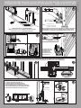 2
2
-
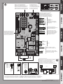 3
3
-
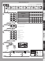 4
4
-
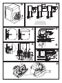 5
5
-
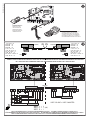 6
6
-
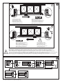 7
7
-
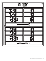 8
8
-
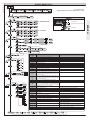 9
9
-
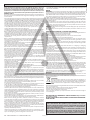 10
10
-
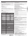 11
11
-
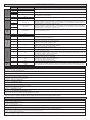 12
12
-
 13
13
-
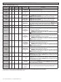 14
14
-
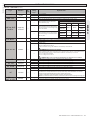 15
15
-
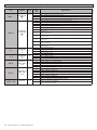 16
16
-
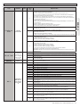 17
17
-
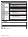 18
18
-
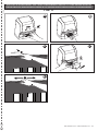 19
19
-
 20
20
-
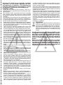 21
21
-
 22
22


BFT Ares Ultra BT A Manuale utente
- Categoria
- Apriporta da garage
- Tipo
- Manuale utente
in altre lingue
- English: BFT Ares Ultra BT A User manual
Documenti correlati
-
BFT Sub BT Manuale utente
-
-
-
-
-
-
-
-
-