ISTRUZIONI D’USO E DI INSTALLAZIONE
INSTALLATION AND USER’S MANUAL
INSTRUCTIONS D’UTILISATION ET D’INSTALLATION
INSTALLATIONS-UND GEBRAUCHSANLEITUNG
INSTRUCCIONES DE USO Y DE INSTALACION
INSTALLATIEVOORSCHRIFTEN
ATTUATORE PER CANCELLI SCORREVOLI A CREMAGLIERA
ACTUATOR FOR RACK SLIDING GATES
ACTIONNEUR POUR PORTAILS COULISSANTS A CREMAILLERE
ANTRIEB FÜR ZAHNSTANGEN-SCHIEBETORE
SERVOMOTOR PARA CANCELAS CORREDERAS DE CREMALLERA
ACTUATOR VOOR SCHUIFHEKKEN MET TANDHEUGEL
Attenzione! Leggere attentamente le “Avvertenze” all’interno! Caution! Read “Warnings” inside carefully! Attention! Veuillez lire attentivement les Avertissements qui se trouvent à l’intérieur!
Achtung! Bitte lesen Sie aufmerksam die „Hinweise“ im Inneren! ¡Atención¡ Leer atentamente las “Advertencias”en el interior! Let op! Lees de “Waarschuwingen” aan de binnenkant zorgvuldig!
D811972 00100_09 28-11-16
DEIMOS BT A 400
DEIMOS BT A 600

2 - DEIMOS BT A 400 - DEIMOS BT A 600
D811972 00100_09
AVVERTENZE PER L’UTILIZZATORE ( I )
ATTENZIONE! Importanti istruzioni di sicurezza.
Leggere e seguire attentamente le Avvertenze
e le Istruzioni che accompagnano il prodotto
poiché un uso improprio può causare danni a
persone, animali o cose. Conservare le istruzioni
per consultazioni future e trasmetterle ad even-
tuali subentranti nell’uso dell’impianto.
Questo prodotto dovrà essere destinato solo
all’uso per il quale è stato espressamente insta-
llato. Ogni altro uso è da considerarsi improprio
e quindi pericoloso. Il costruttore non può essere
considerato responsabile per eventuali danni
causati da usi impropri, erronei e irragionevoli.
SICUREZZA GENERALE
Nel ringraziarVi per la preferenza accordata a questo
prodotto, la Ditta è certa che da esso otterrete le
prestazioni necessarie al Vostro uso.
Questo prodotto risponde alle norme riconosciute
della tecnica e della disposizioni relative alla si-
curezza se correttamente installato da personale
qualicato ed esperto (installatore professionale).
L’automazione, se installata ed utilizzata corretta-
mente, soddisfa gli standard di sicurezza nell’uso.
Tuttavia è opportuno osservare alcune regole di
comportamento per evitare inconvenienti acci-
dentali:
- Tenere bambini, persone e cose fuori dal raggio
d’azione dell’automazione, in particolare durante
il movimento.
- Non permettere a bambini di giocare o sostare nel
raggio di azione dell’automazione.
- L’apparecchio può essere utilizzato da bambini di
età non inferiore a 8 anni e da persone con ridot-
te capacità siche, sensoriali o mentali, o prive di
esperienza o della necessaria conoscenza, purché
sotto sorveglianza oppure dopo che le stesse
abbiano ricevuto istruzioni relative all’uso sicuro
dell’apparecchio e alla comprensione dei pericoli
ad esso inerenti. I bambini non devono giocare con
l’apparecchio. La pulizia e la manutenzione desti-
nata ad essere eettuata dall’utilizzatore non deve
essere eettuata da bambini senza sorveglianza.
- I bambini devono essere sorvegliati per sincerarsi
che non giochino con l’apparecchio. Non permet-
tere ai bambini di giocare con i controlli ssi. Tenere
i telecomandi lontani dai bambini.
-
Evitare di operare in prossimità delle cerniere o organi
meccanici in movimento.
-
Non contrastare il movimento dell’anta e non ten-
tare di aprire manualmente la porta se non è stato
sbloccato l’attuatore con l’apposito sblocco.
-
Non entrare nel raggio di azione della porta o can-
cello motorizzati durante il loro movimento.
- Non lasciare radiocomandi o altri dispositivi di
comando alla portata dei bambini onde evitare
azionamenti involontari.
- L’attivazione dello sblocco manuale potrebbe
causare movimenti incontrollati della porta se in
presenza di guasti meccanici o di condizioni di
squilibrio.
- In caso di apritapparelle: sorvegliare la tapparella
in movimento e tenere lontano le persone nché
non è completamente chiusa. Porre cura quando si
aziona lo sblocco se presente, poiché una tapparella
aperta potrebbe cadere rapidamente in presenza
di usura o rotture.
-
La rottura o l’usura di organi meccanici della porta
(parte guidata), quali ad esempio cavi, molle, sup-
porti, cardini, guide.. potrebbe generare pericoli. Far
controllare periodicamente l’impianto da personale
qualicato ed esperto (installatore professionale)
secondo quanto indicato dall’installatore o dal
costruttore della porta.
- Per ogni operazione di pulizia esterna, togliere
l’alimentazione di rete.
- Tenere pulite le ottiche delle fotocellule ed i dispo-
sitivi di segnalazione luminosa. Controllare che rami
ed arbusti non disturbino i dispositivi di sicurezza.
- Non utilizzare l’automatismo se necessita di
interventi di riparazione. In caso di guasto o di
malfunzionamento dell’automazione, togliere
l’alimentazione di rete sull’automazione, astenersi
da qualsiasi tentativo di riparazione o intervento
diretto e rivolgersi solo a personale qualicato ed
esperto (installatore professionale) per la neces-
saria riparazione o manutenzione. Per consentire
l’accesso, attivare lo sblocco di emergenza (se
presente).
-
Per qualsiasi intervento diretto sull’automazione o
sull’impianto non previsto dal presente manuale,
avvalersi di personale qualicato ed esperto (insta-
llatore professionale).
- Con frequenza almeno annuale far verifi-
care l’integrità e il corretto funzionamento
dell’automazione da personale qualificato ed
esperto (installatore professionale), in particolare
di tutti i dispositivi di sicurezza.
- Gli interventi d’installazione, manutenzione e
riparazione devono essere documentati e la
relativa documentazione tenuta a disposizione
dell’utilizzatore.
- Il mancato rispetto di quanto sopra può creare
situazioni di pericolo.
DEMOLIZIONE
L’eliminazione dei materiali va fatta rispettan-
do le norme vigenti. Non gettate il vostro
apparecchio scartato, le pile o le batterie usate
nei riuti domestici. Avete la responsabilità di
restituire tutti i vostri riuti da apparecchia-
ture elettriche o elettroniche lasciandoli in
un punto di raccolta dedicato al loro riciclo.
Tutto quello che non è espressamente previs-
to nel manuale d’uso, non è permesso. ll buon
funzionamento dell’operatore è garantito solo
se vengono rispettate le prescrizioni riportate
in questo manuale. La Ditta non risponde dei
danni causati dall’inosservanza delle indicazioni
riportate in questo manuale.
Lasciando inalterate le caratteristiche essenziali
del prodotto, la Ditta si riserva di apportare in
qualunque momento le modiche che essa ritie-
ne convenienti per migliorare tecnicamente, cos-
truttivamente e commercialmente il prodotto,
senza impegnarsi ad aggiornare la presente
pubblicazione.
USER WARNINGS (GB)
WARNING! Important safety instructions. Ca-
refully read and comply with the Warnings and
Instructions that come with the product as impro-
per use can cause injury to people and animals
and damage to property. Keep the instructions
for future reference and hand them on to any
new users.
This product is meant to be used only for the
purpose for which it was explicitly installed.
D811767_08

DEIMOS BT A 400 - DEIMOS BT A 600 - 3
D811972 00100_09
AVVERTENZE PER L’UTILIZZATORE ( I )
ATTENZIONE! Importanti istruzioni di sicurezza.
Leggere e seguire attentamente le Avvertenze
e le Istruzioni che accompagnano il prodotto
poiché un uso improprio può causare danni a
persone, animali o cose. Conservare le istruzioni
per consultazioni future e trasmetterle ad even-
tuali subentranti nell’uso dell’impianto.
Questo prodotto dovrà essere destinato solo
all’uso per il quale è stato espressamente insta-
llato. Ogni altro uso è da considerarsi improprio
e quindi pericoloso. Il costruttore non può essere
considerato responsabile per eventuali danni
causati da usi impropri, erronei e irragionevoli.
SICUREZZA GENERALE
Nel ringraziarVi per la preferenza accordata a questo
prodotto, la Ditta è certa che da esso otterrete le
prestazioni necessarie al Vostro uso.
Questo prodotto risponde alle norme riconosciute
della tecnica e della disposizioni relative alla si-
curezza se correttamente installato da personale
qualicato ed esperto (installatore professionale).
L’automazione, se installata ed utilizzata corretta-
mente, soddisfa gli standard di sicurezza nell’uso.
Tuttavia è opportuno osservare alcune regole di
comportamento per evitare inconvenienti acci-
dentali:
- Tenere bambini, persone e cose fuori dal raggio
d’azione dell’automazione, in particolare durante
il movimento.
- Non permettere a bambini di giocare o sostare nel
raggio di azione dell’automazione.
- L’apparecchio può essere utilizzato da bambini di
età non inferiore a 8 anni e da persone con ridot-
te capacità siche, sensoriali o mentali, o prive di
esperienza o della necessaria conoscenza, purché
sotto sorveglianza oppure dopo che le stesse
abbiano ricevuto istruzioni relative all’uso sicuro
dell’apparecchio e alla comprensione dei pericoli
ad esso inerenti. I bambini non devono giocare con
l’apparecchio. La pulizia e la manutenzione desti-
nata ad essere eettuata dall’utilizzatore non deve
essere eettuata da bambini senza sorveglianza.
- I bambini devono essere sorvegliati per sincerarsi
che non giochino con l’apparecchio. Non permet-
tere ai bambini di giocare con i controlli ssi. Tenere
i telecomandi lontani dai bambini.
-
Evitare di operare in prossimità delle cerniere o organi
meccanici in movimento.
-
Non contrastare il movimento dell’anta e non ten-
tare di aprire manualmente la porta se non è stato
sbloccato l’attuatore con l’apposito sblocco.
-
Non entrare nel raggio di azione della porta o can-
cello motorizzati durante il loro movimento.
- Non lasciare radiocomandi o altri dispositivi di
comando alla portata dei bambini onde evitare
azionamenti involontari.
- L’attivazione dello sblocco manuale potrebbe
causare movimenti incontrollati della porta se in
presenza di guasti meccanici o di condizioni di
squilibrio.
- In caso di apritapparelle: sorvegliare la tapparella
in movimento e tenere lontano le persone nché
non è completamente chiusa. Porre cura quando si
aziona lo sblocco se presente, poiché una tapparella
aperta potrebbe cadere rapidamente in presenza
di usura o rotture.
-
La rottura o l’usura di organi meccanici della porta
(parte guidata), quali ad esempio cavi, molle, sup-
porti, cardini, guide.. potrebbe generare pericoli. Far
controllare periodicamente l’impianto da personale
qualicato ed esperto (installatore professionale)
secondo quanto indicato dall’installatore o dal
costruttore della porta.
- Per ogni operazione di pulizia esterna, togliere
l’alimentazione di rete.
- Tenere pulite le ottiche delle fotocellule ed i dispo-
sitivi di segnalazione luminosa. Controllare che rami
ed arbusti non disturbino i dispositivi di sicurezza.
- Non utilizzare l’automatismo se necessita di
interventi di riparazione. In caso di guasto o di
malfunzionamento dell’automazione, togliere
l’alimentazione di rete sull’automazione, astenersi
da qualsiasi tentativo di riparazione o intervento
diretto e rivolgersi solo a personale qualicato ed
esperto (installatore professionale) per la neces-
saria riparazione o manutenzione. Per consentire
l’accesso, attivare lo sblocco di emergenza (se
presente).
-
Per qualsiasi intervento diretto sull’automazione o
sull’impianto non previsto dal presente manuale,
avvalersi di personale qualicato ed esperto (insta-
llatore professionale).
- Con frequenza almeno annuale far verifi-
care l’integrità e il corretto funzionamento
dell’automazione da personale qualificato ed
esperto (installatore professionale), in particolare
di tutti i dispositivi di sicurezza.
- Gli interventi d’installazione, manutenzione e
riparazione devono essere documentati e la
relativa documentazione tenuta a disposizione
dell’utilizzatore.
- Il mancato rispetto di quanto sopra può creare
situazioni di pericolo.
DEMOLIZIONE
L’eliminazione dei materiali va fatta rispettan-
do le norme vigenti. Non gettate il vostro
apparecchio scartato, le pile o le batterie usate
nei riuti domestici. Avete la responsabilità di
restituire tutti i vostri riuti da apparecchia-
ture elettriche o elettroniche lasciandoli in
un punto di raccolta dedicato al loro riciclo.
Tutto quello che non è espressamente previs-
to nel manuale d’uso, non è permesso. ll buon
funzionamento dell’operatore è garantito solo
se vengono rispettate le prescrizioni riportate
in questo manuale. La Ditta non risponde dei
danni causati dall’inosservanza delle indicazioni
riportate in questo manuale.
Lasciando inalterate le caratteristiche essenziali
del prodotto, la Ditta si riserva di apportare in
qualunque momento le modiche che essa ritie-
ne convenienti per migliorare tecnicamente, cos-
truttivamente e commercialmente il prodotto,
senza impegnarsi ad aggiornare la presente
pubblicazione.
USER WARNINGS (GB)
WARNING! Important safety instructions. Ca-
refully read and comply with the Warnings and
Instructions that come with the product as impro-
per use can cause injury to people and animals
and damage to property. Keep the instructions
for future reference and hand them on to any
new users.
This product is meant to be used only for the
purpose for which it was explicitly installed.
D811767_08
Any other use constitutes improper use and,
consequently, is hazardous. The manufacturer
cannot be held liable for any damage as a result
of improper, incorrect or unreasonable use.
GENERAL SAFETY
Thank you for choosing this product. The Firm is
condent that its performance will meet your ope-
rating needs.
This product meets recognized technical standards
and complies with safety provisions when installed
correctly by qualied, expert personnel (professional
installer).
If installed and used correctly, the automated system
will meet operating safety standards. Nonetheless,
it is advisable to observe certain rules of behaviour
so that accidental problems can be avoided:
- Keep adults, children and property out of range of
the automated system, especially while it is moving.
- Do not allow children to play or stand within range
of the automated system.
- The unit can be used by children over 8 years old
and by people with reduced physical, sensory or
mental capabilities or with no experience or neces-
sary knowledge on condition they are supervised
or trained about the safe use of the equipment
and understand the risks involved. Children must
not play with the unit. Cleaning and maintenance
must not be performed by unsupervised children.
- Children must be supervised to ensure they do not
play with the device. Do not allow children to play
with the xed controls. Keep remote controls out
of reach of children.
-
Do not work near hinges or moving mechanical parts.
- Do not hinder the leaf’s movement and do not
attempt to open the door manually unless the ac-
tuator has been released with the relevant release
knob.
- Keep out of range of the motorized door or gate
while they are moving.
- Keep remote controls or other control devices out
of reach of children in order to avoid the automated
system being operated inadvertently.
- The manual release’s activation could result in un-
controlled door movements if there are mechanical
faults or loss of balance.
- When using roller shutter openers: keep an eye
on the roller shutter while it is moving and keep
people away until it has closed completely. Exercise
care when activating the release, if such a device
is tted, as an open shutter could drop quickly in
the event of wear or breakage.
- The breakage or wear of any mechanical parts of
the door (operated part), such as cables, springs,
supports, hinges, guides…, may generate a hazard.
Have the system checked by qualied, expert per-
sonnel (professional installer) at regular intervals
according to the instructions issued by the installer
or manufacturer of the door.
- When cleaning the outside, always cut o mains
power.
- Keep the photocells’ optics and illuminating in-
dicator devices clean. Check that no branches or
shrubs interfere with the safety devices.
- Do not use the automated system if it is in need of
repair. In the event the automated system breaks
down or malfunctions, cut o mains power to the
system; do not attempt to repair or perform any
other work to rectify the fault yourself and instead
call in qualied, expert personnel (professional
installer) to perform the necessary repairs or main-
tenance. To allow access, activate the emergency
release (where tted).
- If any part of the automated system requires direct
work of any kind that is not contemplated herein,
employ the services of qualied, expert personnel
(professional installer).
- At least once a year, have the automated system, and
especially all safety devices, checked by qualied,
expert personnel (professional installer) to make
sure that it is undamaged and working properly.
- A record must be made of any installation, main-
tenance and repair work and the relevant docu-
mentation kept and made available to the user on
request.
- Failure to comply with the above may result in
hazardous situations.
SCRAPPING
Materials must be disposed of in accordance
with the regulations in force. Do not throw
away your discarded equipment or used bat-
teries with household waste. You are respon-
sible for taking all your waste electrical and
electronic equipment to a suitable recycling
centre.
Anything that is not explicitly provided for in the
user guide is not allowed. The operator’s proper
operation can only be guaranteed if the instruc-
tions given herein are complied with. The Firm
shall not be answerable for damage caused by
failure to comply with the instructions featured
herein.
While we will not alter the product’s essential
features, the Firm reserves the right, at any time,
to make those changes deemed opportune to
improve the product from a technical, design or
commercial point of view, and will not be required
to update this publication accordingly.
D811767_08

FIG. 3
C
B
E
click
D
CLOSE
(180°)
(180°)
A
OPEN
MANUALE D’USO: MANOVRA MANUALE/ USER’S MANUAL: MANOVRA MANUALE/ MANUEL D’UTILISATION: MANOVRA MANUALE/ BE-
DIENUNGSANLEITUNG: MANOVRA MANUALE/ MANUEL DE USO: MANOVRA MANUALE/ MANUAL PARA DE USO: MANOVRA MANUALE
8 - DEIMOS BT A 400 - DEIMOS BT A 600
D811972 00100_09

10 - DEIMOS BT A 400 - DEIMOS BT A 600
D811972 00100_09
INSTALLER WARNINGS
Anything that is not explicitly provided for in the installation ma-
nual is not allowed. The operator’s proper operation can only be
guaranteed if the information given is complied with. The Firm shall
not be answerable for damage caused by failure to comply with the
instructions featured herein.
While we will not alter the product’s essential features, the Firm reserves
the right, at any time, to make those changes deemed opportune to
improve the product from a technical, design or commercial point of
view, and will not be required to update this publication accordingly.
WARNING! Important safety instructions. Carefully read and comply with
all the warnings and instructions that come with the product as incorrect
installation can cause injury to people and animals and damage to property.
The warnings and instructions give important information regarding safety,
installation, use and maintenance. Keep hold of instructions so that you can
attach them to the technical le and keep them handy for future reference.
GENERAL SAFETY
This product has been designed and built solely for the purpose indicated herein.
Uses other than those indicated herein might cause damage to the product and
create a hazard.
- The units making up the machine and its installation must meet the requirements
of the following European Directives, where applicable: 2014/30/EC, 2014/35/
EC, 2006/42/EC, 2011/305/EC, 99/05/EC and later amendments. For all countries
outside the EEC, it is advisable to comply with the standards mentioned, in ad-
dition to any national standards in force, to achieve a good level of safety.
- The Manufacturer of this product (hereinafter referred to as the “Firm”) disclaims
all responsibility resulting from improper use or any use other than that for
which the product has been designed, as indicated herein, as well as for failure
to apply Good Practice in the construction of entry systems (doors, gates, etc.)
and for deformation that could occur during use.
- Installation must be carried out by qualied personnel (professional installer,
according to EN 12635), in compliance with Good Practice and current code.
- Before installing the product, make all structural changes required to produce
safety gaps and to provide protection from or isolate all crushing, shearing and
dragging hazard areas and danger zones in general in accordance with the
provisions of standards EN 12604 and 12453 or any local installation standards.
Check that the existing structure meets the necessary strength and stability
requirements.
- Before commencing installation, check the product for damage.
- The Firm is not responsible for failure to apply Good Practice in the construction
and maintenance of the doors, gates, etc. to be motorized, or for deformation
that might occur during use.
- Make sure the stated temperature range is compatible with the site in which the
automated system is due to be installed.
- Do not install this product in an explosive atmosphere: the presence of ammable
fumes or gas constitutes a serious safety hazard.
- Disconnect the electricity supply before performing any work on the system.
Also disconnect buer batteries, if any are connected.
- Before connecting the power supply, make sure the product’s ratings match the
mains ratings and that a suitable residual current circuit breaker and overcurrent
protection device have been installed upline from the electrical system. Have
the automated system’s mains power supply tted with a switch or omnipolar
thermal-magnetic circuit breaker with a contact separation that provide full
disconnection under overvoltage category III conditions.
- Make sure that upline from the mains power supply there is a residual current
circuit breaker that trips at no more than 0.03A as well as any other equipment
required by code.
- Make sure the earth system has been installed correctly: earth all the metal parts
belonging to the entry system (doors, gates, etc.) and all parts of the system
featuring an earth terminal.
- Installation must be carried out using safety devices and controls that meet
standards EN 12978 and EN 12453.
- Impact forces can be reduced by using deformable edges.
- In the event impact forces exceed the values laid down by the relevant standards,
apply electro-sensitive or pressure-sensitive devices.
- Apply all safety devices (photocells, safety edges, etc.) required to keep the
area free of impact, crushing, dragging and shearing hazards. Bear in mind the
standards and directives in force, Good Practice criteria, intended use, the instal-
lation environment, the operating logic of the system and forces generated by
the automated system.
- Apply all signs required by current code to identify hazardous areas (residual
risks). All installations must be visibly identied in compliance with the provisions
of standard EN 13241-1.
- Once installation is complete, apply a nameplate featuring the door/gate’s data.
- This product cannot be installed on leaves incorporating doors (unless the motor
can be activated only when the door is closed).
- If the automated system is installed at a height of less than 2.5 m or is accessible,
the electrical and mechanical parts must be suitably protected.
- For roller shutter automation only
1) The motor’s moving parts must be installed at a height greater than 2.5 m
above the oor or other surface from which they may be reached.
2) The gearmotor must be installed in a segregated and suitably protected space
so that it cannot be reached without the aid of tools.
- Install any xed controls in a position where they will not cause a hazard, away
from moving parts. More specically, hold-to-run controls must be positioned
within direct sight of the part being controlled and, unless they are key operated,
must be installed at a height of at least 1.5 m and in a place where they cannot
be reached by the public.
- Apply at least one warning light (ashing light) in a visible position, and also
attach a Warning sign to the structure.
- Attach a label near the operating device, in a permanent fashion, with informa-
tion on how to operate the automated system’s manual release.
- Make sure that, during operation, mechanical risks are avoided or relevant
protective measures taken and, more specically, that nothing can be banged,
crushed, caught or cut between the part being operated and surrounding parts.
- Once installation is complete, make sure the motor automation settings are
correct and that the safety and release systems are working properly.
- Only use original spare parts for any maintenance or repair work. The Firm dis-
claims all responsibility for the correct operation and safety of the automated
system if parts from other manufacturers are used.
- Do not make any modications to the automated system’s components unless
explicitly authorized by the Firm.
- Instruct the system’s user on what residual risks may be encountered, on the
control systems that have been applied and on how to open the system manu-
ally in an emergency. give the user guide to the end user.
- Dispose of packaging materials (plastic, cardboard, polystyrene, etc.) in accord-
ance with the provisions of the laws in force. Keep nylon bags and polystyrene
out of reach of children.
WIRING
WARNING! For connection to the mains power supply, use: a multicore cable with
a cross-sectional area of at least 5x1.5mm
2
or 4x1.5mm
2
when dealing with three-
phase power supplies or 3x1.5mm
2
for single-phase supplies (by way of example,
type H05RN-F cable can be used with a cross-sectional area of 4x1.5mm
2
). To con-
nect auxiliary equipment, use wires with a cross-sectional area of at least 0.5 mm
2
.
- Only use pushbuttons with a capacity of 10A-250V or more.
- Wires must be secured with additional fastening near the terminals (for example,
using cable clamps) in order to keep live parts well separated from safety extra
low voltage parts.
- During installation, the power cable must be stripped to allow the earth wire
to be connected to the relevant terminal, while leaving the live wires as short
as possible. The earth wire must be the last to be pulled taut in the event the
cable’s fastening device comes loose.
WARNING! safety extra low voltage wires must be kept physically separate from
low voltage wires.
Only qualied personnel (professional installer) should be allowed to access
live parts.
CHECKING THE AUTOMATED SYSTEM AND MAINTENANCE
Before the automated system is nally put into operation, and during maintenance
work, perform the following checks meticulously:
- Make sure all components are fastened securely.
- Check starting and stopping operations in the case of manual control.
- Check the logic for normal or personalized operation.
- For sliding gates only: check that the rack and pinion mesh correctly with 2 mm
of play along the full length of the rack; keep the track the gate slides on clean
and free of debris at all times.
- For sliding gates and doors only: make sure the gate’s running track is straight
and horizontal and that the wheels are strong enough to take the weight of the
gate.
- For cantilever sliding gates only: make sure there is no dipping or swinging
during operation.
- For swing gates only: make sure the leaves’ axis of rotation is perfectly vertical.
-For barriers only: before opening the door, the spring must be decompressed
(vertical boom).
- Check that all safety devices (photocells, safety edges, etc.) are working properly
and that the anti-crush safety device is set correctly, making sure that the force
of impact measured at the points provided for by standard EN 12445 is lower
than the value laid down by standard EN 12453.
- Impact forces can be reduced by using deformable edges.
- Make sure that the emergency operation works, where this feature is provided.
- Check opening and closing operations with the control devices applied.
- Check that electrical connections and cabling are intact, making extra sure that
insulating sheaths and cable glands are undamaged.
- While performing maintenance, clean the photocells’ optics.
- When the automated system is out of service for any length of time, activate the
emergency release (see “EMERGENCY OPERATION” section) so that the operated
part is made idle, thus allowing the gate to be opened and closed manually.
-
If the power cord is damaged, it must be replaced by the manufacturer or their
technical assistance department or other such qualied person to avoid any risk .
- If “D” type devices are installed (as dened by EN12453), connect in unveried
mode, foresee mandatory maintenance at least every six months
- The maintenance described above must be repeated at least once yearly or at
shorter intervals where site or installation conditions make this necessary.
WARNING!
Remember that the drive is designed to make the gate/door easier to use and
will not solve problems as a result of defective or poorly performed installation
or lack of maintenance
SCRAPPING
Materials must be disposed of in accordance with the regulations in
force. Do not throw away your discarded equipment or used batteries
with household waste. You are responsible for taking all your waste
electrical and electronic equipment to a suitable recycling centre.
DISMANTLING
If the automated system is being dismantled in order to be reassembled at another
site, you are required to:
- Cut o the power and disconnect the whole electrical system.
- Remove the actuator from the base it is mounted on.
- Remove all the installation’s components.
- See to the replacement of any components that cannot be removed or happen
to be damaged.
DECLARATIONS OF CONFORMITY CAN BE FOUND AT http://www.bft-
automation.com/CE
INSTRUCTIONS FOR USE AND ASSEMBLY CAN BE FOUND IN THE DOWN-
LOAD SECTION.
D811766_16
ATTENTION ! Instructions de sécurité importantes. Veuillez lire et suivre
attentivement tous les avertissements et toutes les instructions fournis
avec le produit sachant qu’une installation incorrecte peut provoquer des
préjudices aux personnes, aux animaux ou aux biens. Les avertissements
fournissent des indications importantes concernant la sécurité, l’installation,
l’utilisation et l’entretien. Veuillez conserver les instructions pour les joindre
au dossier technique et pour d’ultérieures consultations.
SECURITE GÉNÉRALE
Ce produit a été conçu et réalisé exclusivement pour l’usage indiqué dans cette
documentation. Tout usage autre que celui indiqué risque d’endommager le
produit et d’être une source de danger.
- Les éléments qui composent l’appareil et le montage doivent être conformes
aux Directives Européennes suivantes : 2014/30/CE, 2014/35/CE, 2006/42/CE,
2011/305/CE, 99/05/CE et leurs modications successives. Pour les pays n’ap-
partenant pas à la CEE, il est conseillé de respecter également les normes ci-
tées, outre les règlements nationaux en vigueur, an de garantir un bon niveau
de sécurité.
- Le Fabricant de ce produit (par la suite « le Fabricant ») décline toute respon-
sabilité dérivant d’un usage incorrect ou diérent de celui prévu et indiqué
dans la présente documentation, de l’inobservation de la bonne technique de
construction des huisseries (portes, portails, etc.) et des déformations pouvant
apparaître à l’usage.
-Le montage doit être accompli par du personnel qualié (monteur profession-
nel, conformément à EN12635), dans le respect de la bonne technique et des
normes en vigueur.
- Avant d’installer le produit apportez toutes les modications structurelles
nécessaires pour réaliser les butées de sécurité et la protection ou ségréga-
tion de toutes les zones présentant un risque d’écrasement, de cisaillement,
d’entraînement ou autre, conformément aux normes EN 12604 et 12453 ou les
éventuelles normes locales sur l’installation. - Vériez si la structure existante
est susamment robuste et stable.
- Avant de commencer le montage, vérier l’intégrité du produit.
- Le fabricant décline toute responsabilité en cas d’inobservation de la bonne
technique de construction et d’entretien des huisseries motorisées, ainsi que
de déformations survenant en cours d’utilisation.
- Vérier si l’intervalle de température déclaré est compatible avec le lieu destiné
à l’installation de l’automatisation.
- Ne pas installer ce produit dans une atmosphère explosive: la présence de gaz
ou de fumées inammables constitue un grave danger pour la sécurité.
- Mettre hors tensions l’installation avant d’accomplir une quelconque interven-
tion. Déconnecter également les batteries tampon éventuellement présentes.
- Avant de mettre hors tension, vérier si les données de la plaque d’identica-
tion correspondent à celles du secteur et s’il y a en amont de l’installation élec-
trique un disjoncteur et une protection adéquats contre la surintensité. Pré-
voyez sur le réseau d’alimentation de l’automatisation un interrupteur ou un
magnétothermique omnipolaire permettant de procéder à une déconnexion
totale dans les conditions de la catégorie de surtension III.
- Vérier s’il y a en amont du réseau d’alimentation un disjoncteur dont le seuil
ne dépasse pas 0,03A et les prescriptions des règlements en vigueur.
- Vérier si l’installation de mise à la terre est réalisée correctement. Connecter
toutes les parties métalliques de la fermeture (portes, portails, etc..) et tous les
composants de l’installation munis de borne de terre.
- L’installation doit être équipée de dispositifs de sécurité et de commandes
conformes aux normes EN 12978 et EN12453.
- Les forces de choc peuvent être réduites à l’aide de rebords déformables.
- Si les forces de choc dépassent les valeurs prévues par les normes, appliquer
des dispositifs électrosensibles ou sensibles à la pression.
- Appliquer tous les dispositifs de sécurité (photocellules, linteaux sensibles,
etc..) nécessaires pour protéger la zone contre les risques de choc, d’écrase-
ment, d’entraînement ou de cisaillement. Tenir compte des règlements et des
directives en vigueur, des critères de bonne technique, de l’utilisation, de l’envi-
ronnement de l’installation, de la logique de fonctionnement du système et
des forces développées par l’automatisation.
- Appliquer les signaux prévus par les règlements en vigueur pour indiquer les
zones de danger (risques résiduels). Toutes les installations doivent être identi-
ées de façon visible conformément aux prescriptions de EN13241-1.
- Au terme de l’installation, appliquez une plaque d’identication de la porte/du
portail.
- Ce produit ne peut pas être installé sur des vantaux munis de portes (à moins
que le moteur ne puisse être actionné qu’avec la prote fermée).
bSi l’automatisation est installée à une hauteur inférieure à 2,5 m ou si elle est
accessible, il est indispensable de garantir un degré de protection adapté aux
parties électriques et mécaniques.
- Uniquement pour les automatisations de rideaux
1) Les parties en mouvement du moteur doivent être installées à plus de 2,5
mètres de hauteur au-dessus du sol ou de toute autre niveau servant à y accéder.
2) Le motoréducteur doit être installé dans un espace enfermé et muni de pro-
tection de façon à ce qu’il ne soit accessible qu’avec un outil.
- Installer toutes commandes xes en hauteur de façon à ce qu’elles ne repré-
sentent pas une source de danger et qu’elles soient éloignées des parties
mobiles. En particulier les commandes à homme présent doivent être visibles
directement de la partie guidée et- à moins qu’il n’y ait une clé, se trouver à 1,5 m
minimum de hauteur de façon à être inaccessibles au public.
- Appliquer au moins un dispositif de signalement lumineux (clignotant) visible,
xer également un panneau Attention sur la structure.
- Fixer, à proximité de l’organe de manœuvre et de façon permanente, une éti-
quette sur le fonctionnement du déverrouillage manuel de l’automatisation.
- S’assurer que soient évités pendant la manœuvre les risques mécaniques et, en
particulier, l’écrasement, l’entraînement et le cisaillement par la partie guidée
et les parties voisines.
-
Une fois l’installation accomplie, s’assurer que le réglage du moteur est correct et
que les systèmes de protection et de déverrouillage fonctionnement correctement.
- Utiliser exclusivement des pièces détachées originales pour les opérations
d’entretien ou les réparations. Le Fabricant décline toute responsabilité quant
à la sécurité et au bon fonctionnement de l’automatisation en cas d’utilisation
de composants d’autres Fabricants.
- Ne modier d’aucune façon les composants de l’automatisation sans l’autorisa-
tion expresse du Fabricant.
- Informer l’utilisateur de l’installation sur les risques résiduels éventuels, sur les
systèmes de commande appliqués et sur la façon de procéder à l’ouverture
manuelle en cas d’urgence: remettre le manuel d’utilisation à l’utilisateur nal.
- Eliminer les matériaux d’emballage (plastique, carton, polystyrène, etc.) confor-
Tout ce qui n’est pas expressément prévu dans le manuel de montage
est interdit. Le bon fonctionnement de l’appareil n’est garanti que si
les données indiquées sont respectées. Le Fabricant ne répond pas des
dommages provoqués par l’inobservation des indications données
dans ce manuel.
En laissant inaltérées les caractéristiques essentielles de l’appareil,
l’entreprise se réserve le droit d’apporter à tout moment les modi-
cations qu’elle jugera opportunes pour améliorer le produit du point
de vue technique, commercial et de sa construction, sans s’engager à
mettre à jour la présente publication.
AVERTISSEMENTS POUR LE MONTEUR
mément aux normes en vigueur. Ne pas laisser les sachets en plastique et la
mousse de polystyrène à la portée des enfants.
CONNEXIONS
ATTENTION ! Pour le branchement sur le secteur, utiliser un câble multipolaire
ayant une section minimum de 5x1,5mm
2
ou de 4x1,5mm
2
pour alimentation tri-
phasée ou de 3x1,5mm
2
pour alimentation monophasée (par exemple, le câble
peut être du type H05RN-F avec une section de 4x1,5mm
2
). Pour le branchement
des auxiliaires, utiliser des conducteurs de 0,5 mm
2
de section minimum.
- Utiliser exclusivement des touches ayant une portée supérieure ou égale à
10A-250V.
- Immobiliser les conducteurs à l’aide d’une xation supplémentaire à proximité
des bornes (par exemple, à l’aide d’un collier) an de séparer nettement les
parties sous tension des parties sous très faible tension de sécurité.
-
Pendant l’installation, dénuder le câble d’alimentation an de pouvoir bran-
cher le conducteur de terre sur la borne appropriée en laissant cependant les
conducteurs actifs aussi courts que possibles. Le conducteur de terre doit être
le dernier à se tendre en cas de desserrement du dispositif de xation du câble.
ATTENTION ! Les conducteurs à très faible tension de sécurité doivent être phy-
siquement séparés des conducteurs à basse tension.
Seul le personnel qualié (monteur professionnel) doit pouvoir accéder aux par-
ties sous tension.
VÉRIFICATION DE L’AUTOMATISATION ET ENTRETIEN
Vérier scrupuleusement ce qui suit avant de rendre l’automatisation dénitive-
ment opérationnelle et pendant les interventions d’entretien:
- Vérier si tous les composants sont solidement xés.
- Vérier le fonctionnement du démarrage et de l’arrêt en cas de commande
manuelle.
- Vérier la logique de fonctionnement normale ou personnalisée.
- Uniquement sur les portails coulissants: vérier si l’engrenage crémaillère - pi-
gnon est correct, avec un jeu de 2 mm le long de toute la crémaillère; le rail de
glissement doit être toujours propre et dépourvu de débris.
- Uniquement sur les portails coulissants: vérier si le rail du portail est droit et
horizontal et si les roues sont en mesure de supporter le poids du portail.
- Uniquement sur les portails coulissants suspendus en porte-à-faux: vérier
l’absence d’abaissement ou d’oscillation pendant la manœuvre.
- Uniquement sur les portails à battant : vérier si l’axe de rotation des vantaux
est parfaitement vertical.
-Uniquement pour les barrières: avant d’ouvrir le portillon le ressort doit être
déchargé (barre verticale).
-
Contrôler le bon fonctionnement de tous les dispositifs de sécurité (photocel-
lules, linteaux sensibles etc..) et le bon réglage du dispositif de sécurité anti-écra-
sement, en vériant si la valeur de la force de choc mesurée aux endroits prévus
par la norme EN12445 est inférieure à celle indiquée par la norme EN12453.
- Les forces de choc peuvent être réduites à l’aide de rebords déformables.
- Vérier le bon fonctionnement de la manœuvre d’urgence s’il y en a une.
- Vérier le bon fonctionnement à l’ouverture et à la fermeture avec les disposi-
tifs de commande appliqués.
- Vérier l’intégrité des connexions électriques et des câblages, en particulier
l’état des gaines isolantes et des presse-câbles.
- Pendant les opérations d’entretien, nettoyer les lentilles des photocellules.
- Pendant la période de mise hors service de l’automatisation, activer le déver-
rouillage d’urgence (cf. paragraphe MANŒUVRE D’URGENCE) de façon à libérer
la partie guidée et à pouvoir accomplir l’ouverture et la fermeture manuelles
due portail.
- Si le câble d’alimentation est endommagé, il doit être remplacé par le constructeur
ou par son service après-vente ou par une personne qualiée, an d’éviter tout
risque.
- Si on installe des dispositifs du type D (tels que dénis par la EN12453), branchés
en mode non vérié, prescrire un entretien obligatoire au moins tous les six mois.
- L’entretien décrit plus haut doit être répété au moins une fois par an ou plus
fréquemment si les caractéristiques du site ou de l’installation le demandent.
ATTENTION !
Ne pas oublier que la motorisation facilite l’utilisation du portail/de la porte
mais qu’elle ne résout pas les problèmes imputables à des défauts ou à des
erreurs de montage ou encore à l’absence d’entretien.
DÉMOLITION
Eliminez les matériaux en respectant les normes en vigueur. Ne jetez
ni les vieux appareils, ni les piles, ni les batteries usées avec les ordures
domestiques. Vous devez coner tous vos déchets d’appareils électri-
ques ou électroniques à un centre de collecte diérenciée, préposé à
leur recyclage.
DÉMANTÈLEMENT
Si l’automatisation est démontée pour ensuite être remontée sur un autre site, il faut:
- Couper l’alimentation et débrancher toute l’installation électrique.
- Retirer l’actionneur de la base de xation.
- Démonter tous les composants de l’installation.
- Remplacer les composants ne pouvant pas être retirés ou endommagés.
LES DÉCLARATIONS DE CONFORMITÉ PEUVENT ÊTRE CONSULTÉES SUR LE
SITE INTERNET http://www.bft-automation.com/CE
LES INSTRUCTIONS DE MONTAGE ET D’UTILISATION PEUVENT ÊTRE CON-
SULTÉES DANS LA SECTION DOWNLOAD/TÉLÉDÉCHARGEMENT.
D811766_16

INSTALLAZIONE VELOCE-QUICK INSTALLATION-INSTALLATION RAPIDE
SCHNELLINSTALLATION-INSTALACIÓN RÁPIDA - SNELLE INSTALLATIE
2x0.75mm
2
3x1.5mm
2
RG58
3x1.5mm
2
3x1.5mm
2
5x0,75mm
2
2x1.5mm
2
Predisposizione fissaggio motore, Preparation for motor mounting,
Aménagement fixation moteur, Vorbereitung Motorbefestigung,
Disposición fijación del motor, Voorbereiding bevestiging motor.
17mm + “X”
“X”=Cremagliera (FIG J), Rack (FIG J),
Crémaillère (FIG J), Zahnstange (FIG J),
Cremallera (FIG J), Tandheugel (FIG J)
Montaggio motore,
Mounting the motor,
Montage moteur,
Montage Motor,
Montaje del motor,
Montage motor.
Montaggio accessori trasmissione, Mounting drive accessories,
Montage accessoires transmission, Montage Antriebszubehör,
Montaje de accesorios transmisión, Montage accessoires overbrenging.
Y + 50 mm
> 10mm
> 25mm
60-70mm
A
D
B
E
PREDISPOSIZIONE TUBI,
TUBE ARRANGEMENT,
PRÉDISPOSITION DES TUYAUX, VORBEREITUNG DER LEITUNGEN,
DISPOSICIÓN DE TUBOS, VOORBEREIDING LEIDINGEN.
1
2
C
4
3A 3B
4
3
Y
Fissaggio staffe finecorsa (dx e sx), Fastening limit switch brackets (RH/LH),
Fixation étriers fin de course (drt et gch), Befestigung Bügel Anschläge (rechts und links),
Fijación abrazaderas final de carrera (der. e izq.),
Bevestiging stangen aanslag (rechts en links).
F
E1
C1
ITALIANO ENGLISH
FRANÇAIS
DEUTSCH
ESPAÑOL
NEDERLANDS
DEIMOS BT A 400 - DEIMOS BT A 600 - 15
D811972 00100_09
LET OP! Belangrijke veiligheidsinstructies. De waarschuwingen en de instructies
die met het product meegeleverd worden zorgvuldig lezen en volgen, aangezien
verkeerde installatie schade aan personen, dieren of voorwerpen kan veroorzaken.
De waarschuwingen en de instructies geven belangrijke aanwijzingen over de
veiligheid, de installatie, het gebruik en het onderhoud. De instructies bewaren
om ze aan de technische folder toe te voegen voor toekomstige raadpleging.
ALGEMENE VEILIGHEID
Dit product is uitsluitend ontworpen en gebouwd voor het gebruik aangegeven
in deze documentatie. Soorten gebruik anders dan hetgeen aangegeven, zouden
schade aan het product en gevaar kunnen veroorzaken.
- De constructie-elementen van de machine en de installatie moeten overeenkom-
stig de volgende Europese Richtlijnen zijn, indien toepasbaar: 2014/30/CE, 2014/35/
CE, 2006/42/CE,
2011/305/CE, 99/05/CE en daaropvolgende wijzigingen. Voor alle
landen buiten de EEG is het voor een goed veiligheidsniveau nuttig om naast de
nationaal geldende normen, ook de genoemde normen in acht te nemen.
- Het Bedrijf wijst iedere willekeurige verantwoordelijkheid af voortkomende uit een
verkeerd gebruik of een ander gebruik dan het voorbestemde gebruik en dat aan-
gegeven in deze documentatie, evenals uit het niet in acht nemen van het Goed
Gebruik bij de constructie van de sluitingen (deuren, hekken, etc..) en uit de vervor-
mingen die tijdens het gebruik zouden kunnen optreden.
- De installatie moet worden uitgevoerd door gekwaliceerd personeel (professio-
nele installateur, volgens EN12635), met inachtneming van het Goed Gebruik en de
geldende normen.
- Alvorens het product te installeren, alle structurele wijzigingen aanbrengen betref-
fende de verwezenlijking van de vrijboorden en de beveiliging of afscheiding van
alle zones met gevaar voor pletting, snijden, meeslepen en algemeen gevaar, vol-
gens hetgeen voorgeschreven wordt door de normen EN 12604 en 12453 of even-
tuele plaatselijke installatienormen. Controleren of de bestaande structuur over de
noodzakelijke vereisten beschikt wat betreft stevigheid en stabiliteit.
-
Alvorens te beginnen met de installatie, de goede toestand van het product controleren.
- Het bedrijf is niet verantwoordelijk voor het niet naleven van het Goed Gebruik bij
de constructie en het onderhoud van de te motoriseren kozijnen, en van de vervor-
mingen die zich tijdens het gebruik kunnen voordoen.
- Controleren of het opgegeven temperatuurinterval compatibel is met de plek be-
stemd voor de installatie van het automatiseringssysteem.
- Dit product niet in een explosieve omgeving installeren: de aanwezigheid van gas of
ontvlambare rookgassen vormt een ernstig gevaar voor de veiligheid.
-
De stroomvoorziening uitschakelen vóór wat voor werkzaamheden dan ook aan de
installatie. Ook eventuele buerbatterijen loskoppelen, indien aanwezig.
-
Voordat men de elektrische voeding aansluit, moet men controleren of de gegevens
op de plaat overeenstemmen met die van het elektriciteitsnet en of er stroomop-
waarts de elektrische installatie een geschikte dierentiële drukschakelaar en een
geschikte bescherming tegen overstroom staat. Op het voedingsnet van het auto-
matiseringssysteem een omnipolaire (magneet)schakelaar voorzien waarmee een
volledige uitschakeling mogelijk is in de omstandigheden van overspanningscate-
gorie III.
-
Controleren of er zich aan het begin van het voedingsnet een aardlekschakelaar bevindt
die de drempel van max. 0,03A en de geldende normen niet overschrijdt.
- Controleren of het aardingssysteem correct is uitgevoerd: alle metalen delen van
de sluiting (deuren, hekken, etc.) en alle onderdelen van de installatie voorzien van
aardingsklemmen aarden.
- De installatie moet worden uitgevoerd met gebruik van veiligheidsinrichtingen en
bedieningen overeenkomstig EN 12978 en EN12453.
- De botsingskrachten kunnen verminderd worden door middel van het gebruik van
vervormbare randen.
-
In het geval dat de botsingskrachten de door de normen voorziene waarden over-
schrijden, inrichtingen aanbrengen die gevoelig zijn voor elektriciteit of druk.
- Alle veiligheidsinrichtingen (fotocellen, gevoelige randen, etc.) aanbrengen die
noodzakelijk zijn om het gebied te beschermen tegen gevaren voor botsing, plet-
ting, meeslepen en snijden. Rekening houden met de geldende normen en richtlij-
nen, de criteria van het Goed Gebruik, het gebruik, de installatieomgeving, de wer-
king van het systeem en de door het automatiseringssysteem ontwikkelde krachten.
-
De door de geldende normen voorziene signalen aanbrengen om de gevaarlijke zo-
nes aan te duiden (de restrisico’s). Iedere installatie moet op zichtbare wijze worden
geïdenticeerd volgens hetgeen voorgeschreven door de EN13241-1.
- Na de installatie voltooid te hebben, een identicatieplaat van de deur / het hek
aanbrengen.
-
Dit product mag niet worden geïnstalleerd op vleugels waarin deuren zijn opgeno-
men (tenzij de motor uitsluitend kan worden geactiveerd wanneer de deur dicht is).
- Als het automatiseringssysteem is geïnstalleerd op een hoogte van minder dan 2,5
m of als het toegankelijk is, is het noodzakelijk een passende beschermingsgraad
van de elektrische en mechanische delen te garanderen.
- Alleen voor automatiseringssystemen voor rolluiken
1) De bewegende delen van de motor moeten op een minimale hoogte van 2,5 m
boven de vloer of een ander niveau waar de toegang mogelijk is geïnstalleerd worden.
2) De reductiemotor moet in een afgescheiden ruimte geïnstalleerd worden voorzien
van een beveiliging zodat hij alleen met gebruik van gereedschap toegankelijk is.
-
Iedere willekeurige vaste bediening zo installeren, dat deze geen gevaar vormt en
ver van beweegbare delen is. In het bijzonder de bedieningen bij aanwezige persoon
moeten direct zichtbaar zijn vanaf het geleide deel, en, tenzij het gaat om bedieningen
met sleutel, moeten deze worden geïnstalleerd op een hoogte van minstens 1,5 m en
zodanig dat ze niet toegankelijk zijn voor het publiek.
- Minstens één signaleringsinrichting (knipperend) aanbrengen in een zichtbare posi-
tie, en daarnaast een bordje “Let op” aan de structuur bevestigen.
- Op permanente wijze een etiket aanbrengen met betrekking tot de werking van de
handmatige deblokkering van het automatiseringssysteem en dit in de buurt van de
manoeuvreringsinrichting aanbrengen.
- Zorg ervoor dat tijdens de manoeuvre de mechanische risico’s vermeden en bevei-
ligd worden en dan met name de botsing, de pletting, het meeslepen, het snijden
tussen geleide deel en omliggende delen.
- Na de installatie te hebben uitgevoerd, zich ervan verzekeren dat de instelling van
het automatiseringssysteem van de motor juist is uitgevoerd en dat de beveiligings-
en deblokkeringssystemen juist functioneren.
-
Uitsluitend originele reserveonderdelen gebruiken voor alle onderhouds- of repara-
tiewerkzaamheden. Het Bedrijf wijst iedere willekeurige verantwoordelijkheid af uit
veiligheidsredenen en vanwege de goede werking van het automatiseringssysteem,
als er onderdelen van andere fabrikanten gebruikt worden.
- Geen enkele wijziging uitvoeren aan de componenten van het automatiseringssys-
teem, indien niet uitdrukkelijk door het Bedrijf geautoriseerd.
-
De gebruiker van de installatie instructies geven wat betreft de restrisico’s, de toege-
paste bedieningssystemen en de uitvoering van de handmatige openingsmanoeuvre
in geval van nood: de gebruikershandleiding aan de eindgebruiker overhandigen.
Al hetgeen niet uitdrukkelijk voorzien is in de installatiehandleiding, is
niet toegestaan. De goede werking van de controller is alleen gegaran-
deerd, als de vermelde gegevens in acht worden genomen. Het bedrijf is
niet gehouden zich te verantwoorden voor de schade veroorzaakt door
het niet in acht nemen van de aanwijzingen vermeld in deze handleiding.
Terwijl de hoofdkenmerken van het product ongewijzigd blijven, behoudt
het Bedrijf zich het recht voor om op ieder willekeurig moment die wijzi-
gingen aan te brengen die zij geschikt acht om het product technisch,
constructief en commercieel gezien te verbeteren, zonder deze publicatie
te hoeven bijwerken.
WAARSCHUWINGEN VOOR DE INSTALLATEUR
- Verpakkingsmaterialen (plastic, karton, polystyrol, etc.) verwerken volgens hetgeen
voorzien is door de geldende normen. Nylon zakjes en polystyrol buiten bereik van
kinderen bewaren.
AANSLUITINGEN
LET OP! Gebruik voor de aansluiting op het netwerk: meeraderige kabel met een
doorsnede van min. 5x1,5 mm
2
of 4x1,5 mm
2
voor driefase voeding of 3x1,5 mm
2
voor eenfase voeding (de kabel moet bijvoorbeeld van het type H05RN-F met
doorsnede 4x1,5 mm
2
zijn).Voor de aansluiting van de hulpapparatuur geleiders
gebruiken met een doorsnede van min. 0,5 mm
2
.
-
Uitsluitend drukknoppen gebruiken met een werkbelasting van min. 10A-250V.
- De geleiders moeten verbonden worden door een extra bevestiging in de buurt
van de klemmen (bijvoorbeeld met behulp van bandjes) om de delen onder
spanning duidelijk gescheiden te houden van de delen met zeer lage veiligheids-
spanning.
- Tijdens de installatie moet de stroomtoevoerkabel van zijn bekleding ontdaan
worden, zodat de aansluiting van de aardgeleider op de geschikte klem mogelijk
wordt, terwijl de actieve geleiders echter zo kort mogelijk gelaten worden. De
aardgeleider moet de laatste zijn die gerekt wordt in geval van losraken van de
bevestigingsinrichting van de kabel.
OPGELET! de geleiders met zeer lage veiligheidsspanning moeten fysiek geschei-
den worden van de geleiders met lage spanning.
De toegang tot de delen onder spanning mag uitsluitend mogelijk zijn voor het
gekwaliceerde personeel (professionele installateur)
CONTROLE VAN HET AUTOMATISERINGSSYSTEEM EN ONDERHOUD
Alvorens het automatiseringssysteem in werking te stellen, en tijdens de onder-
houdswerkzaamheden, nauwgezet het volgende nagaan:
- controleren of alle onderdelen stevig zijn bevestigd;
-
de opstart- en stophandelingen in het geval van de handmatige besturing controle-
ren;
- de normale of gepersonaliseerde werking controleren.
- Alleen voor schuifhekken: de correcte ineengrijping tandheugel-rondselas met
een speling van 2 mm over de hele tandheugel controleren; de looprail altijd
schoon houden en vrij van afval.
- Alleen voor schuifhekken en –deuren: controleren of de glijrail recht en horizon-
taal is en of de wielen geschikt zijn voor het gewicht van het hek.
- Alleen voor hangende schuifhekken (Cantilever): controleren of het hek niet zakt
of trilt tijdens de manoeuvre.
- Alleen voor vleugelpoorten: controleren of de rotatie-as van de vleugels perfect
verticaal is.
- Alleen voor slagbomen: alvorens het deurtje te openen, moet de veer ontladen
zijn (slagboom verticaal).
-
De juiste werking van alle veiligheidsinrichtingen controleren (fotocellen, gevoe-
lige randen, etc.) en de correcte afstelling van de antibeklemmings-veiligheidsin-
richting door te controleren of de waarde van de botsingskracht gemeten in de
punten voorzien door de norm EN12445, lager is dan hetgeen aangegeven in de
norm EN 12453.
- De botsingskrachten kunnen verminderd worden door middel van het gebruik
van vervormbare randen.
- De functionaliteit van de noodmanoeuvre controleren, indien aanwezig.
- De openings- of sluitingshandeling met de aangebrachte bedieningsinrichtin-
gen controleren.
- De goede toestand van de elektrische aansluitingen en van de bekabelingen
controleren, met name de status van de isolatiekousen en de kabelleiders.
- Tijdens het onderhoud de reiniging van de optieken van de fotocellen uitvoeren.
- Voor de periode waarin het automatiseringssysteem buiten bedrijf is, de nood-
deblokkering activeren (zie paragraaf “NOODMANOEUVRE”) om het geleide deel
los te maken en zo de handmatige opening en sluiting van het hek mogelijk te
maken.
- Indien de voedingskabel beschadigd is, moet deze vervangen worden door de
fabrikant of door diens technische assistentiedienst of alleszins door een persoon
met een soortgelijke kwalicatie, teneinde alle risico’s te voorkomen.
- Als er inrichtingen type “D” geïnstalleerd worden (zoals gedefinieerd door
EN12453),die anders dan trusted aangesloten zijn, verplicht halaarlijks onderhoud
voorschrijven.
- Het onderhoud dat hierboven is beschreven moet minstens eenmaal per jaar of
vaker als de plaats of de installatie dit vereist, worden verricht.
LET OP!
Vergeet niet dat de motoraandrijving een gemak is bij het gebruik van het hek /
de poort en geen oplossing biedt voor problemen door defecten en installatiege-
breken of gebrek aan onderhoud.
SLOOP
De materialen moeten verwijderd worden met inachtneming van de
geldende normen. Uw niet meer gebruikte apparaat, de lege batterijen
of accu’s niet bij het huisvuil weggooien. U bent er verantwoordelijk voor
al uw afval van elektrische of elektronische apparatuur weg te brengen
naar een inzamelpunt voor de recycling ervan.
ONTMANTELING
In het geval dat het automatiseringssysteem gedemonteerd wordt om op een an-
dere plek opnieuw gemonteerd te worden, is het nodig:
-
De stroomvoorziening uit te schakelen en de hele elektrische installatie los te kop-
pelen.
- De actuator van de bevestigingsbasis te verwijderen.
- Alle onderdelen van de installatie te demonteren.
- In het geval dat enkele onderdelen niet verwijderd kunnen worden of bescha-
digd blijken te zijn, deze vervangen.
DE CONFORMITEITSVERKLARINGEN KUNNEN WORDEN INGEZIEN OP DE
WEBSITE http://www.bft-automation.com/CE
DE MONTAGE- EN GEBRUIKSAANWIJZINGEN KUNNEN WORDEN INGEZIEN
IN HET DEEL DOWNLOAD.
D811766_16

G
Y #
ANT
SHIELD
Antenna
Antenne
Antena
Antenne
+
+
+
Tasti programmazione,
Programming keys,
touches de programmation,
Programmierungstasten,
botones de programacion,
Toetsen programmeur.
F3 1,25A T
F1
Connettore necorsa
Limit switch connector
Connecteur de n de course
Steckverbindung Endschalter
Conector nal de carrera
Connector eindaanslag
ERR
SET
RADIO
24V -
24V +
24 VSafe+
COM
START
OPEN
NO
NO
Alimentazione accessori
Accessories power supply
Alimentation des accessoires
Stromversorgung Zubehör
Alimentación accesorios
Voeding accessoires
Comandi / Commands
Commandes/Bedienelemente
Mandos/ Commando's
PHOT
STOP
COM
FAULT 1
BAR
FAULT 2
NC
NC
NC
Sicurezze
Safety devices
Sécurités
Sicherheitsvorrichtungen
Dispositivos de seguridad
Veiligheden
Alimentazione / Power supply
Alimentation / Stromversorgung
Alimentación /Voeding
L
N
220-230V ~
*
M1
+
-
Motore / Motor / moteur
Motor /Eindaanslag/Encoder
Lampeggiante / Blinker / Clignotant
Warnblinkleuchte / Bombilla / Knipperlicht
+ REF SWE
SWC
SWO
10L N 11 20 21 41 42 43
50 51 52 60 61 62 70 71 72 73 74 75
S1 S2 S3
FAULT2
FAULT1
PHOT
STOP
OPEN
START
BAR
H
Collegamento di 1 coppia di fotocellule non vericate, per fotocellule vericate vedere pagine seguenti.
Connection of 1 couple of untested photocells, for tested photocells see the following pages.
Connexion d’une paire de photocellules non vériées, pour les photocellules vériées consultez les pages suivantes.
Anschluss von einem Paar nicht überprüfter Fotozellen, für überprüfte Fotozelle siehe die folgenden Seiten.
Conexión de 1 par de fotocélulas no comprobadas, para fotocélulas comproabdas véanse las siguientes páginas.
Aansluiting van 1 paar niet-geverieerde fotocellen. Raadpleeg de volgende pagina’s voor geverieerde fotocellen.
24V
!
24V~
220-230V~*
JP3
24V
2
1
TX1
2
1
RX1
4
5
3
50 51
70 72
DIP3=OFF
POWER
SWO
SWC
START
+ +
S3 S3
X1X1
START STOP
F1 DEIMOS BT A 400 DEIMOS BT A 600
110-120V 1,6AT 1,6AT
220-230V 0,63AT 0,8AT
16 - DEIMOS BT A 400 - DEIMOS BT A 600
D811972 00100_09

ITALIANO ENGLISH
FRANÇAIS
DEUTSCH
ESPAÑOL
NEDERLANDS
J
I
I1
1
verso di apertura: destra
opening direction: right
sens de l’ouverture : droite
Önungsrichtung: rechts
sentido de apertura: derecha
openingsrichting: rechtsverso
2
verso di apertura: sinistra
opening direction: left
sens de l’ouverture : gauche
Önungsrichtung: links
sentido de apertura: izquierda
openingsrichting: links
START
OK
S1
S1
S1
MEMORIZZAZIONE RADIOCOMANDO/MEMORIZING REMOTE CONTROLS/MÉMORISATION RADIOCOMMANDE
ABSPEICHERUNG DER FERNBEDIENUNG /MEMORIZACIÓN DEL RADIOMANDO/MEMORIZAÇÃO DO RADIOCOMANDO
x1
S1 S2 S3
RADIO RADIO RADIO
Fisso
Steadily lit
Fixe
Ununterbrochen an
Fijo
Continu
Lampeggio continuo
Continuous ashing
Clignotement continu
Kontinuierliches Blinken
Parpadeo continuo
Continu knipperen
Lampeggio intermittente
Intermittent ashing
Clignotement intermittent
intermittierendes Blinken
Parpadeo intermitente
Met intervallen knipperen
LEGENDA - KEY - LÉGENDE
LEGENDE - LEYENDA - LEGENDA
=
AUTO OPEN
AUTO CLOSE
AUTO OPEN
AUTO CLOSE
5s
S1 S2 S3
S2S1 S3
SET
S2S1 S3
SET
S2S1 S3
SET
OK KO
REGOLAZIONE AUTOSET, ADJUSTING AUTOSET, RÉGLAGE AUTOSET ,
EINSTELLUNG AUTOSET, REGULACIÓN AUTOSET, REGULAÇÃO AUTOSET.
10 11
M
10 11
M
41 4342
41 4342
DEIMOS BT A 400 - DEIMOS BT A 600 - 17
D811972 00100_09

CP
X= 37
30
12
CVZ
28
60
X= 33
30
8
CVZ-S
6
X= 40
NO
OK
N1
39
50
255
120
135
164
287
K
L
M
N
P
P1
50
>25
>100
17
2mm
O
Q
S
Q1
Q3
Q2
18 - DEIMOS BT A 400 - DEIMOS BT A 600
D811972 00100_09

R
BAR 8K2
50
51
52
70
71
72
73
74 75
24V ~
24V ~
24 VSafe
COM
PHOT
BAR
STOP
FAULT 1
FAULT 2
NC
NC
NC
PHOT
1
2
1
2
3
4
5
51
TX1 RX1
1
2
1
2
3
4
5
52
50
TX1 RX1
1
2
1
2
3
4
5
TX1 RX1
1
2
1
2
3
4
5
TX2 RX2
1
2
1
2
3
4
5
TX1 RX1
1
2
1
2
3
4
5
TX1 RX1
1
2
1
2
3
4
5
TX1 RX1
1
2
1
2
3
4
5
TX2 RX2
1 PHOT / 1 PHOT CL
1 PHOT / 1 PHOT CL
2 PHOT / 2 PHOT CL
BAR 8K2
50
52
50
52
50
51
50
51
50
51
50
51
50
70
72
70
72
73
70
70
72
73
BAR
Bar 1
1
2
3
4
5
6
Bar 1
1
2
3
4
5
Bar 2
1
2
3
4
5
Bar 1
1
2
3
4
5
6
6
6
Bar 1
1
2
3
4
5
6
Bar 1
1
2
3
4
5
Bar 2
1
2
3
4
5
Bar 1
1
2
3
4
5
6
6
6
51
51
50
51
50
51
50
52
52
52
74
70
74
70
75
74
70
51
50
70
75
70
74
8,2Kohm 5%
SAFETY EDGE
SAFETY EDGE
DIP2 OFF
DIP4 OFFDIP4 ON
DIP2 ON
DIP3 OFFDIP3 ON
*
1 BAR/ 1BAR CL
**
1 BAR TEST/ 1 BAR CL TEST
***
2 BAR TEST/ 2 BAR CL TEST
****
BAR 8K2/ BAR CL 8K2
ITALIANO ENGLISH
FRANÇAIS
DEUTSCH
ESPAÑOL
NEDERLANDS
DEIMOS BT A 400 - DEIMOS BT A 600 - 19
D811972 00100_09

INSTALLATION MANUAL
1) GENERAL INFORMATION
The DEIMOS BT A actuator is highly versatile in terms of installation options due
to the extremely low position of the pinion, the actuator’s compact nature and the
height and depth adjustment features it oers. The adjustable electronic torque
limiter provides anti-crush safety. Manual emergency operation is extremely easy
to perform using just a release lever.
Stopping at end of travel is controlled by electromechanical microswitches.
The HAMAL control panel comes with standard factory settings.
Any change must be set by means of the TRIMMER and DIP SWITCH settings.
Its main features are:
- Control of 1 low-voltage motor
- Obstacle detection
- Separate inputs for safety devices
- Built-in radio receiver rolling code with transmitter cloning.
The board has a terminal strip of the removable kind to make maintenance
or replacement easier. It comes with a series of prewired jumpers to make the
installer’s job on site easier. The jumpers concern terminals: 70-71, 70-72, 70-74.
If the above-mentioned terminals are being used, remove the relevant jumpers.
TESTING
The HAMAL panel controls (checks) the start relays and safety devices (photocells)
before performing each opening and closing cycle.
If there is a malfunction, make sure that the connected devices are working
properly and check the wiring.
2) TECHNICAL SPECIFICATIONS
MOTOR
400 600
Power supply
110-120V 50/60Hz
220-230V 50/60 Hz(*)
110-120V 50/60Hz
220-230V 50/60 Hz(*)
Motor 24V
24V
Power input 50W 70W
Max. current demand
0,5A (230V
~
) - 1A
(110V
~
)
0,5A (230V
~
) - 1A
(110V
~
)
Pinion module (standard) 4mm (14 teeth) 4mm (14 teeth)
Leaf speed (standard) 12m/min 12m/min
Max. leaf weight - standard** 4000N (≈400kg) 6000N (≈600kg)
Pinion module (fast) 4mm (18 teeth) 4mm (18 teeth)
Leaf speed (fast) 15.5m/min 15.5m/min
Max. leaf weight - fast** 3000N (≈300kg) 3600N (≈360kg)
Max. torque 20Nm 30Nm
Impact reaction
Electronic torque
limiter
Electronic torque
limiter
Lubrication Lifetime greased Lifetime greased
Manual operation
Lever-operated
mechanical release
Lever-operated
mechanical release
Type of use intensive intensive
Buffer batteries (optional
extras)
Two 12V 1.2Ah bat-
teries
Two 12V 1.2Ah bat-
teries
Environmental conditions from -20°C to +55°C from -20°C to +55°C
Protection rating IP24 IP24
Noise level <70dBA <70dBA
Operator weight 7kg (≈70N) 7kg (≈70N)
Dimensions See Fig. K See Fig. K
CONTROL UNIT
Low voltage/mains insulation > 2MOhm 500V
Operating temperature range -20 / +55°C
Thermal overload protection Software
Dielectric rigidity mains/LV 3750V~ for 1 minute
Accessories power supply 24V
(demand max. 0,2A) 24V safe
AUX 0 - BLINKER NO 24V
powered contact (max.1A)
Fuses Fig. G
Built-in Rolling-Code
radio-receiver
frequency 433.92MHz
Setting of parameters and
logics
TRIMMER + DIP SWITCH
N° of combinations 4 billion
Max. n° of remotes that can
be memorized
63
Maximum work time 3 minutes
Pedestrian opening space 30% of the total travel (not modiable)
(*) Special supply voltages to order.
** There are no minimum or maximum dimension restrictions for the guided
part that can be used
Usable transmitter versions:
All ROLLING CODE transmitters compatible with
.
3) TUBE ARRANGEMENT Fig.A
Install the electrical system referring to the standards in force for electrical systems
CEI 64-8, IEC 364, harmonization document HD 384 and other national standards.
4) PREPARATION FOR MOTOR MOUNTING FIG.B
Make a hole in the ground to accommodate the concrete pad, with anchors
embedded in the base plate for fastening the gearbox assembly, keeping to the
distances featured in FIG.B.
5) REMOVING THE COVER Fig.C
• Unscrewtherelevanttwofrontscrews(FIG.C-rif.1)
• Pushasillustrated(FIG.C-rif.2-rif.3)toreleasethecoverfromthetworear
blocks (FIG.C - rif.3A e FIG.C - rif.3B).
• Liftthecover(FIG.C-rif.4).
6) MOUNTING THE MOTOR FIG.D
7) MOUNTING DRIVE ACCESSORIES FIG.E-E1
Recommended rack types (FIG.L)
8) RACK CENTRING WITH RESPECT TO PINION FIG.M-N1-O
DANGER - Welding must be performed by a competent person issued
with the necessary personal protective equipment as prescribed by
the safety rules in force FIG.L.
9) FASTENING LIMIT SWITCH BRACKETS FIG.F
10) STOPS FIG.P
DANGER - The gate must be tted with mechanical stops to halt its
travel both when opening and closing, thus preventing the gate from
coming o the top guide. Said stops must be fastened rmly to the ground,
a few centimetres beyond the electric stop point.
Note: the safety edge P1 must be installed so that it is not triggered by the
mechanical stops.
11) MANUAL RELEASE (See USER GUIDE -FIG.3-).
Warning Do not JERK the gate open and closed, instead push it GENTLY to
the end of its travel.
12) TERMINAL BOARD WIRING Fig. G-Q
Once suitable electric cables have been run through the raceways and the auto-
mated device’s various components have been fastened at the predetermined
points, the next step is to connect them as directed and illustrated in the dia-
grams contained in the relevant instruction manuals. Connect the live, neutral
and earth wire (compulsory).The mains cable must be clamped in the relevant
cable gland (FIG.Q-ref.Q1) and in the grommet (FIG.Q-ref.Q2), while the earth
wire with the yellow/green-coloured sheath must be connected in the relevant
terminal (FIG.Q-ref.S) and the extra low voltage wires must be run through the
relevant grommet (FIG.Q ref.Q3).
WARNINGS - When performing wiring and installation, refer to the standards
in force and, whatever the case, apply good practice principles. Wires carrying
dierent voltages must be kept physically separate from each other, or they must
be suitably insulated with at least 1mm of additional insulation.
Wires must be secured with additional fastening near the terminals, using devi-
ces such as cable clamps. All connecting cables must be kept far enough away
from dissipaters.
12.1) LOCAL COMMANDS Fig. G
Pressing the S3 key commands one START. By pressing the key again while the
automated device is moving a STOP is commanded.
13) SAFETY DEVICES
Note: only use receiving safety devices with free changeover contact.
13.1) TESTED DEVICES Fig.R
13
.2 CONNECTION OF 1 PAIR OF NONTESTED PHOTOCELLS FIG. H
14 MEMORIZING TRANSMITTERS FIG. I
RADIO
- IMPORTANT NOTE: THE FIRST TRANSMITTER MEMORIZED MUST BE
IDENTIFIED BY ATTACHING THE KEY LABEL (MASTER).
In the event of manual programming, the rst transmitter assigns the RECEIVER’S
KEY CODE: this code is required to subsequently clone the radio transmitters.
The Clonix built-in on-board receiver also has a number of important advanced
features:
• Cloningofmastertransmitter(rollingcodeorxedcode).
• Cloningtoreplacetransmittersalreadyenteredinreceiver.
24 - DEIMOS BT A 400 - DEIMOS BT A 600
D811972 00100_09

ENGLISH
INSTALLATION MANUAL
Terminal Denition Description
Power supply
L LINE
Single-phase power supply
220-230V ~50/60 Hz*
N NEUTRAL
JP31
TRANSF PRIM
Transformer primary winding connection, 220-230V
~.
JP32
JP13 TRANSF SEC
Board power supply:
24V~ Transformer secondary winding
Motor
10 MOT +
Connection motor 1
11 MOT -
Aux
20
AUX 0 -BLINKER
24V (N.O.) (MAX. 1A)
Contact stays closed while leaf is operating.
21
Limit
switches
41 +REF SWE Limit switch common
42 SWC Closing limit switch SWC (N.C.)
43 SWO Opening limit switch SWO (N.C.)
Accessories
power
supply
50 24V-
Accessories power supply output.
51 24V+
52 24 Vsafe+
Tested safety device power supply output (photocell transmitter and safety edge transmitter).
Output active only during operating cycle.
Commands
60
Common START and OPEN inputs common
61
Only active on FW < 3.03
START
START command button (N.O.).
Operation according to “3/4-STEP” logic
Only active on FW ≥ 3.03
START
START command button (N.O.).
Operation according to “Residential / apartment building operation” logic
62
OPEN
OPEN command button (N.O.).
Gate opened with this command. If the input stays closed, the leaves stay open until the contact is opened.
When the contact is open, the automated device closes following the TCA time, where activated.
Safety devices
70 Common STOP, PHOT and BAR inputs common
71 STOP
The command stops movement. (N.C.)
If not used, leave jumper inserted.
72 PHOT (*)
PHOTOCELL input (N.C.).
Operation according to “PHOTOCELL/PHOTOCELL DURING CLOSING” logic. If not used, leave jumper inserted.
73
FAULT 1 Test input for safety devices connected to PHOT.
74
Only active on FW < 3.03
BAR (*)
BAR safety edge input (N.C.).
Congurable according to the “BAR/ 8K2” logic.
The command reverses movement for 2 sec.
If not used, leave jumper inserted.
Only active on FW ≥ 3.03
BAR /
BAR CL /
BAR TEST /
BAR CL TEST /
BAR 8K2 /
BAR CL 8K2
(*)
Safety edge input (N.C.).
If not used, leave jumper inserted
BAR/8K2
dip
Safety
edge
check dip
Safety edge
operation
dip
OFF OFF OFF NC input, no verication, reversal while opening and closing (BAR)
OFF OFF ON NC input, no verication, reversal only when closing, stop when
opening (BAR CL)
OFF ON OFF NC input, with verication, reversal while opening and closing
(BAR TEST)
OFF ON ON NC input, with verication, reversal only when closing, stop when
opening (BAR CL TEST)
ON OFF OFF 8K2 input, reversal when opening and closing (BAR 8K2)
ON OFF ON 8K2 input, reversal only when closing, stop when opening (BAR
CL 8K2)
ON ON OFF ---
ON ON ON ---
75
FAULT 2 Test input for safety devices connected to BAR.
Antenna
Y ANTENNA
Antenna input.
Use an antenna tuned to 433MHz. Use RG58 coax cable to connect the Antenna and Receiver. Metal bodies
close to the antenna can interfere with radio reception. If the transmitter’s range is limited, move the antenna
to a more suitable position.
# SHIELD
*) If “D” type devices are installed (as dened by EN12453), connect in unveried mode, foresee mandatory maintenance at least every six months.
TABLE “A” PARAMETERS
TRIMMER Parameter
+
min.
+
max.
Description
T1
Automatic
closing time [s]
0 120
Waiting time before automatic closing.
NOTE: Set to 0 if not used.
T2 Leaf force [%]
10 90
Force exerted by leaf/leaves.This is the percentage of force delivered, beyond the force stored during the
autoset cycle (and subsequently updated), before an obstacle alarm is generated.
WARNING: It aects impact force directly: make sure that current safety requirements are met
with the set value (*). Install anti-crush safety devices where necessary.
T3
Slow-down
distance [%]
5 50
Set opening slow-down speed as a percentage of total travel. This distance is travelled at low speed.
NOTE: When this parameter is edited, a new Autoset cycle must be run to conrm it.
(*) In the European Union, apply standard EN 12453 for force limitations, and standard EN 12445 for measuring method.
DEIMOS BT A 400 - DEIMOS BT A 600 -
25
D811972 00100_09

INSTALLATION MANUAL
TABLE “B” LOGICS
DIP Logic Default
Cross out
setting used
Description
1
Transmitter
programming
ON
ON
Enables wireless memorizing of transmitters:
1- Press in sequence the hidden key and normal key (T1-T2-T3-T4) of a transmitter that has already
been memorized in standard mode via the radio menu.
2-
Press within 10 sec. the hidden key and normal key (T1-T2-T3-T4) of a transmitter to be memorized.
The receiver exits programming mode after 10 sec.: you can use this time to enter other new
transmitters.
This mode does not require access to the control panel.
IMPORTANT: Enables the automatic addition of new transmitters, clones and replays.
OFF
Disables wireless memorizing of transmitters and automatic addition of clones.
Transmitters are memorized only using the relevant Radio menu or automatically with replays.
IMPORTANT: Disables the automatic addition of new transmitters and clones
2 BAR / 8K2 OFF
ON
Input congured as Bar 8k2. Input for resistive edge 8K2.
The command reverses movement for 2 sec.
OFF
Input congured as Bar, safety edge.
The command reverses movement for 2 sec.
3
Photocell input
check
OFF
ON Enable safety check on the PHOT input
OFF Safety check on PHOT input not enabled
4 Edge input check OFF
ON Enable safety check on the BAR input
OFF Safety check on BAR input not enabled
5
Photocells
during closing
OFF
ON
In the event beam is broken, photocell operation is disabled during opening. During closing,
movement is reversed immediately.
OFF
When beam is broken, photocells are active during both opening and clo-
sing. When beam is broken during closing, movement is reversed only once the
photocell is cleared.
Only active on FW < 3.03
6 Fast closing OFF
ON Closes 3 seconds after the photocells are cleared before waiting for the set TCA to elapse.
OFF Logic not enabled
7
Block pulses
during opening
OFF
ON The start pulse has no eect during opening.
OFF The start pulse has eect during opening.
8 3-step logic OFF
ON
Switches to 3-step logic; during closing, start
reverses movement.
3 step 4 step
CLOSED
opens
opens
DURING CLOSING stop
OPEN closes closes
DURING OPENING
stop +
TCA
stop +
TCA
AFTER STOP opens opens
OFF Switches to 4-step logic.
Only active on FW ≥ 3.03
6
Safety edge input
operation
OFF
ON Safety edge with active reversal only when closing, when opening the movement stops
OFF Safety edge with active reversal in both directions
7 Fast closing OFF
ON Closes 3 seconds after the photocells are cleared before waiting for the set TCA to elapse.
OFF Logic not enabled
8
Residential /
apartment
building
operation
OFF
ON
Sets the automation type of operation:
ON = Apartment building
OFF OFF = Residential
Reaction to the START input (wired or radio):
Residential Apartment building
CLOSED Opens Opens
WHILE CLOSING Stops Opens
OPEN Closes Closes
WHILE OPENING STOPS + TCA No eect
AFTER STOP Opens Opens
Reaction to the OPEN input (wired):
Residential Apartment building
CLOSED Opens Opens
WHILE CLOSING Opens Opens
OPEN No eect No eect
WHILE OPENING Keeps it open Keeps it open
AFTER STOP Opens Opens
Reaction to the PEDESTRIAN input (radio):
Residential Apartment building
CLOSED Opens partially Opens partially
WHILE CLOSING Stops Opens partially
OPEN Closes Closes
WHILE OPENING STOPS + TCA No eect
AFTER STOP Opens partially Opens partially
26 - DEIMOS BT A 400 - DEIMOS BT A 600
D811972 00100_09

ENGLISH
INSTALLATION MANUAL
• Transmitterdatabasemanagement.
• Receivercommunitymanagement.
To use these advanced features, refer to the universal handheld programmer’s
instructions and to the general receiver programming guide.
15 AUTOSET ADJUSTMENT FIG. I1
Enables Motor Torque to be set automatically.
If the power is suddenly disconnected and then restored the automation performs
the operations at autoset speed till the travel limits are identied.
WARNING!! The autoset operation must be performed only once you have che-
cked that the leaf is moving accurately (opening/closing) and that the mechanical
stops are positioned correctly.
You must run an autoset cycle whenever the slow-down distance (T3) .
WARNING! While the autoset function is running, the obstacle detection function
is not active. Consequently, the installer must monitor the automated device’s
movements and keep people and property out of range of the automated device.
WARNING: the torque values set by the autoset function refer to the motor force
set during the autoset cycle. If motor force is edited, an autoset opening and
closing cycle will need to be performed again.
WARNING: check that the force of impact measured at the points provided for
by standard EN 12445 is lower than the value laid down by standard EN 12453.
Setting sensitivity incorrectly can result in damage to property and injury to
people and animals.
16)REVERSING THE OPENING DIRECTION (Fig.S)
KEYS
KEYS Description
S1
Add Start Key
associates the desired key with the Start command.
S2
Add Pedestrian Key
associates the desired key with the pedestrian command.
(Pedestrian opening space, see technical specications)
S2
>5s
Conrms the changes made to parameter settings and operating
S1+S2
>10s
Erase List
WARNING! Erases all memorized transmitters from the
receiver’s memory.
S3
Pressed BRIEFLY, it gives the START command.
HELD DOWN (>5 sec.), it activates the AUTOSET function.
LED INDICATORS:
POWER Steadily lit: - Mains power on - Board powered - Fuse F1 intact
START Lit: START input activated
OPEN Lit: OPEN input activated
STOP Unlit: STOP input activated
PHOT Unlit: PHOT photocell input activated
FAULT 1 PHOT input safety device test input diagnostics
BAR Unlit: BAR safety edge input activated
FAULT 2 BAR input safety device test input diagnostics
SWC
Unlit: leaf fully closed
Lit: motor limit switch is disengaged
SWO
Unlit: leaf fully open
Lit: motor limit switch is disengaged
ERR
Unlit: no error
LIT: see error diagnostics table
RADIO
(GREEN)
Unlit: remote programming not active
Radio LED only ashing: Remote programming active, waiting for
hidden key.
Flashing in sync with Set LED: Transmitter deletion in progress
Lit: remote programming active, waiting for desired key.
Lit 1s: Radio receiver channel activated
SET
Lit: Set key pressed / Autoset completed successfully
Flashes three times: Autoset in progress
Fast ashing 10s: Autoset failed
Flashing in sync with Radio LED: Transmitter deletion in progress
Lit 1s: Start/Stop after key S3 pressed
Lit 10s: Autoset completed correctly
17 ADJUSTMENT PROCEDURE
Before turning the unit on, check electrical connections.
- Set the following parameters: Automatic Closing Time, motor force, slow-down
distance.
- Set the logics.
- Run the autoset function.
WARNING! Incorrect settings can result in damage to property and injury
to people and animals.
WARNING: Check that the force of impact measured at the points
provided for by standard EN 12445 is lower than the value laid down
by standard EN 12453.
For best results, it is advisable to run the autoset function with the motors idle (i.e.
not overheated by a considerable number of consecutive operations)
18) INSTALLATION TEST PROCEDURE
1. Run the AUTOSET cycle (*)
2. Check the impact forces: if they fall within the limits (**) skip to point 9 of the
procedure, otherwise
3. Where necessary, adjust the sensitivity (force) parameter: see parameters table.
4. Check the impact forces again: if they fall within the limits (**) skip to point 9
of the procedure, otherwise
5. Apply a shock absorber prole
6. Check the impact forces again: if they fall within the limits (**) skip to point 9
of the procedure, otherwise
7. Apply pressure-sensitive or electro-sensitive protective devices (such as a
safety edge) (**)
8. Check the impact forces again: if they fall within the limits (**) skip to point 9
of the procedure, otherwise
9. Make sure all devices designed to detect obstacles within the system’s operating
range are working properly
(*) Before running the autoset function, make sure you have performed all the
assembly and make-safe operations correctly, as set out in the installation
warnings in the drive’s manual.
(**) Based on the risk analysis, you may nd it necessary to apply sensitive
protective devices anyway
WARNING! Incorrect settings can result in damage to property and injury to people
and animals.
LED ERR:
Led ERR
Led SET Lit slow ashing fast ashing
Unlit:
Reverse due to
obstacle - Ampe-
rostop
- Check for obsta-
cles in path
Photocell test,
Costa o Costa 8k2
failed
- Check photocell
connection and/or
logic settings
Thermal cutout
- Allow automated
device to cool
Lit
Internal system
supervision control
error.
- Try switching the
board o and back
on again.
If the problem
persists, contact
the technical
assistance de-
partment.
Limit switch error
- Check limit
switch connec-
tions
slow
ashing
Photocell test
failed
- Check photocell
connection and/or
logic settings
Parameters and/
or Operating Logic
edited
- If the “Slow-down
distance” is edited,
run a new Autoset
cycle to conrm
the new setting.
- If other parame-
ters and/or opera-
ting logic are edi-
ted, hold down S2
for 5s to conrm.
NOTE: In any case,
the Autoset fun-
ction conrms all
changes made to
the board.
DEIMOS BT A 400 - DEIMOS BT A 600 -
27
D811972 00100_09

ITALY
-
 1
1
-
 2
2
-
 3
3
-
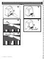 4
4
-
 5
5
-
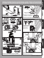 6
6
-
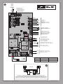 7
7
-
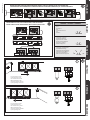 8
8
-
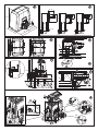 9
9
-
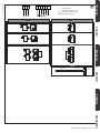 10
10
-
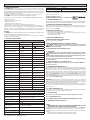 11
11
-
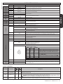 12
12
-
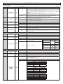 13
13
-
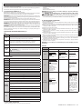 14
14
-
 15
15


in altre lingue
- English: BFT Deimos BT A User manual
Documenti correlati
-
BFT Eos 1200 U Manuale utente
-
-
-
-
-
-
-
-
BFT Vista SLC Manuale utente
-