eMachines D845GVSR Manuale utente
- Categoria
- Schede madri
- Tipo
- Manuale utente
Questo manuale è adatto anche per

Intel
®
Desktop Board
D845GVSR Product Guide
Order Number: C45520-001

Revision History
Revision Revision History Date
-001 First release of the Intel
®
Desktop Board D845GVSR Product Guide. July 2003
If an FCC declaration of conformity marking is present on the board, the following statement applies:
FCC Declaration of Conformity
This device complies with Part 15 of the FCC Rules. Operation is subject to the following two conditions: (1) this device
may not cause harmful interference, and (2) this device must accept any interference received, including interference that
may cause undesired operation.
For questions related to the EMC performance of this product, contact:
Intel Corporation
5200 N.E. Elam Young Parkway
Hillsboro, OR 97124
1-800-628-8686
This equipment has been tested and found to comply with the limits for a Class B digital device, pursuant to Part 15 of the
FCC Rules. These limits are designed to provide reasonable protection against harmful interference in a residential
installation. This equipment generates, uses, and can radiate radio frequency energy and, if not installed and used in
accordance with the instructions, may cause harmful interference to radio communications. However, there is no guarantee
that interference will not occur in a particular installation. If this equipment does cause harmful interference to radio or
television reception, which can be determined by turning the equipment off and on, the user is encouraged to try to correct
the interference by one or more of the following measures:
• Reorient or relocate the receiving antenna.
• Increase the separation between the equipment and the receiver.
• Connect the equipment to an outlet on a circuit other than the one to which the receiver is connected.
• Consult the dealer or an experienced radio/TV technician for help.
Any changes or modifications to the equipment not expressly approved by Intel Corporation could void the user’s authority
to operate the equipment.
Canadian Department of Communications Compliance Statement
This digital apparatus does not exceed the Class B limits for radio noise emissions from digital apparatus set out in the
Radio Interference Regulations of the Canadian Department of Communications.
Le présent appareil numerique német pas de bruits radioélectriques dépassant les limites applicables aux appareils
numériques de la classe B prescrites dans le Réglement sur le broullage radioélectrique édicté par le ministére des
Communications du Canada.
Disclaimer
Information in this document is provided in connection with Intel
®
products. No license, express or implied, by estoppel or
otherwise, to any intellectual property rights is granted by this document. Except as provided in Intel’s Terms and
Conditions of Sale for such products, Intel assumes no liability whatsoever, and Intel disclaims any express or implied
warranty, relating to sale and/or use of Intel products including liability or warranties relating to fitness for a particular
purpose, merchantability, or infringement of any patent, copyright or other intellectual property right. Intel products are not
intended for use in medical, life saving, or life sustaining applications. Intel may make changes to specifications and
product descriptions at any time, without notice.
Desktop Board D845GVSR may contain design defects or errors known as errata which may cause the product to deviate
from published specifications. Current characterized errata are available on request.
Contact your local Intel sales office or your distributor to obtain the latest specifications and before placing your product
order.
Copies of documents which have an ordering number and are referenced in this document, or other Intel literature, may be
obtained from Intel Corporation by going to the World Wide Web site at: http://www.intel.com/ or by calling
1-800-548-4725.
Intel, Celeron and Pentium are trademarks or registered trademarks of Intel Corporation or its subsidiaries in the United
States and other countries.
* Other names and brands may be claimed as the property of others.
Copyright © 2003, Intel Corporation. All rights reserved.

iii
Preface
This Product Guide gives information about board layout, component installation, BIOS Setup
menus, and regulatory requirements for Intel
®
Desktop Board D845GVSR.
Intended Audience
The Product Guide is intended for technically qualified personnel. It is not intended for general
audiences.
Information Layout
The chapters in this Product Guide are arranged as follows:
1 Desktop Board Features
: a summary of product features.
2 Installing and Replacing Desktop Board Components
: instructions on how to install the desktop
board and other hardware components.
3 Updating the BIOS
: instructions on how to update the BIOS.
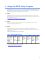
4 Using the BIOS Setup Program
: contents of the BIOS Setup menus and submenus
5 Desktop Board Resources
: information about desktop board resources.
A Error Messages and Indicators
: information about BIOS error messages and beep codes.
B Regulatory Compliance
: safety and EMC regulations, product certification.
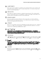
Conventions
The following conventions are used in this manual:
WARNING
Warnings indicate conditions that, if not observed, can cause personal injury.
CAUTION
Cautions warn the user about how to prevent damage to hardware or loss of data.
NOTE
Notes call attention to important information.

Intel Desktop Board D845GVSR Product Guide
iv
Terminology
The table below gives descriptions to some common terms used in the product guide.
Term Description
GB Gigabyte (1,073,741,824 bytes)
GHz Gigahertz (one billion hertz)
KB Kilobyte (1024 bytes)
MB Megabyte (1,048,576 bytes)
Mbit Megabit (1,048,576 bits)
MHz Megahertz (one million hertz)
Box Contents
• Intel Desktop Board
• I/O shield
• One IDE cable
• One diskette drive cable
• Quick Reference Guide
• Configuration and battery caution statement label
• Intel
®
Express Installer CD-ROM

v
Contents
1 Desktop Board Features
Desktop Board Components ...............................................................................................11
Processor............................................................................................................................13
Main Memory ......................................................................................................................14
Intel
®
845GV Chipset ..........................................................................................................15
Audio Subsystem ................................................................................................................15
LAN Subsystem (Optional)..................................................................................................16
LAN Subsystem Software...........................................................................................16
RJ-45 LAN Connector LEDs.......................................................................................16
Hi-Speed USB 2.0 Support..................................................................................................16
Enhanced IDE Interface ......................................................................................................17
Expansion Slots...................................................................................................................17
BIOS ...................................................................................................................................17
PCI Auto Configuration...............................................................................................17
IDE Auto Configuration...............................................................................................17
Security Passwords....................................................................................................18
Power Management Features .............................................................................................18
Speaker...............................................................................................................................20
Battery.................................................................................................................................20
Real-Time Clock..................................................................................................................20
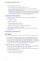
2 Installing and Replacing Desktop Board Components
Before You Begin ................................................................................................................21
Installation Precautions .......................................................................................................22
Installation Instructions........................................................................................................22
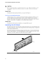
Installing the I/O Shield .......................................................................................................24
Installing and Removing the Desktop Board........................................................................25
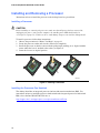
Installing and Removing a Processor ..................................................................................26
Installing a Processor .................................................................................................26
Installing the Processor Fan Heatsink ........................................................................26
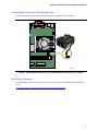
Connecting the Processor Fan Heatsink Cable ..........................................................27
Removing a Processor ...............................................................................................27
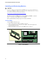
Installing and Removing Memory ........................................................................................28
Installing DIMMs.........................................................................................................28
Removing DIMMs.......................................................................................................29
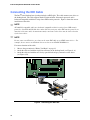
Connecting the IDE Cable ...................................................................................................30
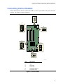
Connecting Internal Headers...............................................................................................31
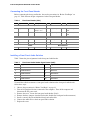
Connecting the Front Panel Header ...........................................................................32
Installing a Front Panel Audio Solution .......................................................................32
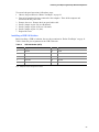
Installing a USB 2.0 Solution ......................................................................................33
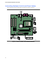
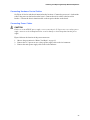
Connecting Hardware Control and Power Cables ...............................................................34
Connecting Hardware Control Cables.........................................................................35
Connecting Power Cables ..........................................................................................35

Intel Desktop Board D845GVSR Product Guide
vi
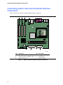
Connecting Add-In Card and Peripheral Interface Connectors ............................................36
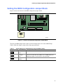
Setting the BIOS Configuration Jumper Block.....................................................................37
Clearing Passwords ............................................................................................................38
Back Panel Connectors.......................................................................................................39
Replacing the Battery ..........................................................................................................40
3 Updating the BIOS
Updating the BIOS with the Intel
®
Express BIOS Update Utility ..........................................45
Updating the BIOS with the Intel
®
Iflash BIOS Update Utility...............................................45
Obtaining the BIOS Update File..................................................................................45
Updating the BIOS......................................................................................................46
Recovering the BIOS..................................................................................................46
4 Using the BIOS Setup Program
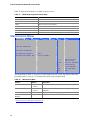
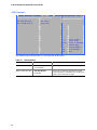
Maintenance Menu..............................................................................................................50
Main Menu ..........................................................................................................................51
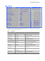
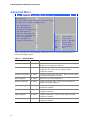
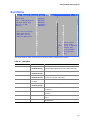
Advanced Menu ..................................................................................................................52
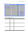
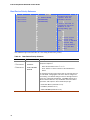
PCI Configuration Submenu .......................................................................................53
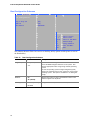
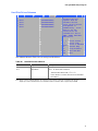
Boot Configuration Submenu......................................................................................54
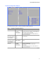
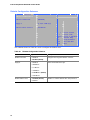
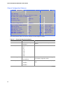
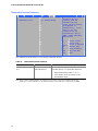
Peripheral Configuration Submenu.............................................................................55
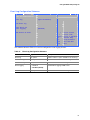
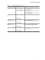
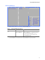
IDE Configuration Submenu .......................................................................................57
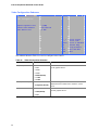
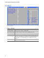
Primary/Secondary IDE Master/Slave Submenus.......................................................58
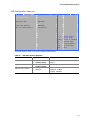
Diskette Configuration Submenu ................................................................................60
Event Log Configuration Submenu .............................................................................61
Video Configuration Submenu....................................................................................62
USB Configuration Submenu......................................................................................63
Chipset Configuration Submenu .................................................................................64
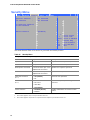
Security Menu .....................................................................................................................66
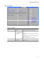
Power Menu........................................................................................................................67
ACPI Submenu...........................................................................................................68
Boot Menu...........................................................................................................................69
Boot Device Priority Submenu....................................................................................70
Hard Disk Drives Submenu ........................................................................................71
Removable Devices Submenu....................................................................................72
ATAPI CD-ROM Drives ..............................................................................................73
Exit Menu ............................................................................................................................74
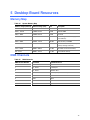
5 Desktop Board Resources
Memory Map .......................................................................................................................75
DMA Channels ....................................................................................................................75
Interrupts.............................................................................................................................76
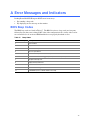
A Error Messages and Indicators
BIOS Beep Codes...............................................................................................................77
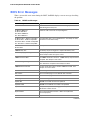
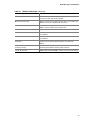
BIOS Error Messages .........................................................................................................78

Contents
vii
B Regulatory Compliance
Safety Regulations ..............................................................................................................81
European Union Declaration of Conformity Statement ........................................................81
Product Ecology Statements ...............................................................................................82
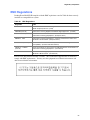
EMC Regulations ................................................................................................................83
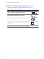
Product Certification Markings (Board Level) ......................................................................84
Figures
1. Desktop Board Components.........................................................................................11
2. Location of Standby Power Indicator.............................................................................19
3. Installing the I/O Shield.................................................................................................24
4. Desktop Board Mounting Screw Holes..........................................................................25
5. Installing a Processor....................................................................................................26
6. Connecting the Processor Fan Heatsink Cable to the Processor Fan Header ..............27
7. Installing Memory..........................................................................................................28
8. Connecting the IDE Cable.............................................................................................30
9. Internal Headers ...........................................................................................................31
10. Location of Hardware Control and Power Connectors ..................................................34
11. Add-in Card and Peripheral Interface Connectors.........................................................36
12. Location of the BIOS Configuration Jumper Block ........................................................37
13. Back Panel Connectors ................................................................................................39
14. Removing the Battery from the Desktop Board.............................................................43

Intel Desktop Board D845GVSR Product Guide
viii
Tables
1. Feature Summary .......................................................................................................... 9
2. Desktop Board Components.........................................................................................12
3. Processors Supported by the Desktop Board ...............................................................13
4. Memory Support ...........................................................................................................14
5. RJ-45 LAN Connector LEDs .........................................................................................16
6. Front Panel Header (J9G1)...........................................................................................32
7. Front Panel Audio Header Signal Names (J8A1) ..........................................................32
8. USB 2.0 Header (J9F2) ................................................................................................33
9. Jumper Settings for the BIOS Setup Program Modes (J9H2) .......................................37
10. BIOS Setup Program Menu Bar....................................................................................49
11. BIOS Setup Program Function Keys.............................................................................50
12. Maintenance Menu .......................................................................................................50
13. Main Menu....................................................................................................................51
14. Advanced Menu............................................................................................................52
15. PCI Configuration Submenu .........................................................................................53
16. Boot Configuration Submenu ........................................................................................54
17. Peripheral Configuration Submenu ...............................................................................55
18. IDE Configuration Submenu .........................................................................................57
19. Primary/Secondary IDE Master/Slave Submenus.........................................................58
20. Diskette Configuration Submenu ..................................................................................60
21. Event Log Configuration Submenu ...............................................................................61
22. Video Configuration Submenu ......................................................................................62
23. USB Configuration Submenu ........................................................................................63
24. Chipset Configuration Submenu ...................................................................................64
25. Security Menu...............................................................................................................66
26. Power Menu..................................................................................................................67
27. ACPI Submenu .............................................................................................................68
28. Boot Menu ....................................................................................................................69
29. Boot Device Priority Submenu ......................................................................................70
30. Hard Disk Drives Submenu...........................................................................................71
31. Removable Devices Submenu......................................................................................72
32. ATAPI CD-ROM Drives Submenu.................................................................................73
33. Exit Menu......................................................................................................................74
34. System Memory Map....................................................................................................75
35. DMA Channels..............................................................................................................75
36. Interrupts ......................................................................................................................76
37. Beep Codes..................................................................................................................77
38. BIOS Error Messages...................................................................................................78
39. Safety Regulations........................................................................................................81
40. EMC Regulations..........................................................................................................83
41. Product Certification Markings ......................................................................................84

9
1 Desktop Board Features
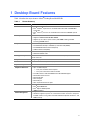
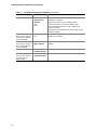
Table 1 describes the major features of Intel
®
Desktop Board D845GVSR.
Table 1. Feature Summary
Form Factors
MicroATX at 9.2 inches by 8.2 inches
Processor
Support for:
• Intel
®
Pentium
®
4 processor in an mPGA-478 socket with a 533/400 MHz
system bus
• Intel
®
Celeron
®
processor in an mPGA-478 socket with a 400 MHz system
bus
Memory
• Two 184-pin DDR SDRAM DIMM sockets, 2.5 V
• Support for DDR333/266/200 MHz DIMMs
• Supports up to 2 GB of system memory with DIMMs utilizing 512 Mbit
technology DRAM devices
Chipset
Intel
®
845GV chipset, consisting of:
• Intel
®
82845GV Grahpics and Memory Controller Hub (GMCH)
• Intel
®
82801DB I/O Controller Hub (ICH4)
• 4 Mbit Firmware Hub (FWH)
Audio
• Intel 845GV chipset (AC ’97)
• Realtek ALC202A codec
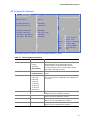
LAN (Optional)
Intel
®
82562ET 10/100 Mbit/sec Platform LAN Connect (PLC) device and
RJ-45 connector
Graphics
Integrated graphics
I/O Control
SMSC LPC47M172 low pin count (LPC) interface I/O controller
Expansion Capabilities
Three PCI slots
Peripheral Interfaces
• Up to six USB 2.0 ports
— Four ports routed to the back panel
— Two ports routed to the USB 2.0 header
• Two IDE interfaces with Ultra DMA-33 and ATA-66/100 support
• One diskette drive interface
• One parallel port
• One serial port
• One VGA port
• PS/2* keyboard and mouse ports
BIOS
• Intel/AMI BIOS
• Intel
®
Rapid BIOS Boot
• Intel
®
Express BIOS Update
• SMBIOS support
Power Management
• Support for Advanced Configuration and Power Interface (ACPI)
• Hardware support for power, fan, and chassis intrusion connectors, Suspend
to RAM, resume on ring, wake from USB and PS/2 keyboard and mouse, and
PME# wakeup.

Intel Desktop Board D845GVSR Product Guide
10
✏
NOTE
For information about this Intel desktop board, including the Technical Product Specification
(TPS), BIOS updates, and device drivers, go to the Intel World Wide Web site at:
http://support.intel.com/support/motherboards/desktop/
Supported Operating Systems
The desktop board supports the following operating systems:
• Microsoft Windows* 98 SE
• Microsoft Windows Me
• Microsoft Windows 2000
• Microsoft Windows XP

Desktop Board Features
11
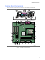
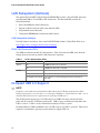
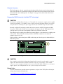
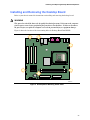
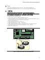
Desktop Board Components
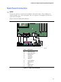
Figure 1 shows the location of the major components on Desktop Board D845GVSR.
OM16272
F
E
I
J
K
L
M
N
O
P
H
Q
R
T
C
A
G
S
U
B
Line
In
USB 2.0
USB 2.0
D
Figure 1. Desktop Board Components

Intel Desktop Board D845GVSR Product Guide
12
Table 2. Desktop Board Components
Item Description
A Front panel audio header
B Auxiliary line-in header
C CD-in (ATAPI) header
D 12 V power connector
E Rear chassis fan header
F Processor socket
G Processor fan header
H DIMM sockets
I Main power connector
J Diskette drive connector
K Secondary IDE connector
L Primary IDE connector
M Speaker
N Battery
O Auxiliary front panel power LED connector
P Front chassis fan header
Q Chassis intrusion header
R BIOS
S Front panel header
T Front panel USB header
U PCI connectors
Related Links:
Go to the following links for more information about Intel Desktop Board D845GVSR:
• http://www.intel.com/design/motherbd
• http://support.intel.com/support/motherboards/desktop

Desktop Board Features
13
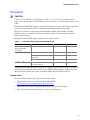
Processor
CAUTION
Failure to use an ATX12V or SFX-12V power supply, or not connecting the additional power
supply lead to Desktop Board D845GVSR may result in damage to the desktop board and/or power
supply.
Desktop Board D845GVSR supports a single Intel Pentium 4 processor or Intel Celeron processor.
Processors are not included with the desktop board and must be purchased separately.
The processor connects to the desktop board through the mPGA-478-pin socket. The Intel
Pentium 4 processor or Intel Celeron processor may be removed and replaced with supported
higher speed processors.
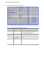
Desktop Board D845GVSR supports the processors listed in Table 3.
Table 3. Processors Supported by the Desktop Board
Type Designation (GHz) System Bus (MHz) L2 Cache (KB)
Intel
®
Pentium
®
4
processor with HT
Technology
3.06 533 512
2.80, 2.66, 2.53, 2.40B, and 2.26 533 512
2.60, 2.50, 2.40, 2.20, 2A, 1.80A,
and 1.60A
400 512
Intel Pentium 4 processor
2, 1.90, 1.80, 1.70, 1.60, and 1.50 400 256
Intel
®
Celeron
®
processor 2.60, 2.50, 2.40, 2.30, 2.20, 2.10,
2.0, 1.80, and 1.70
400 128
Desktop Board D845GVSR requires an ATX12V compliant power supply to function according to
desktop board specifications. The board has two ATX12V compliant power supply connectors
that are needed to provide extra power to the Intel 845GV chipset and Intel processor.
Related Links:
Go to the following links or pages for more information about:
• Supported Intel processors for Desktop Board D845GVSR
http://support.intel.com/support/motherboards/desktop/
• Instructions on installing or upgrading the processor, see page 26 in Chapter 2
• The location of the two power connectors, see page 34 in Chapter 2.

Intel Desktop Board D845GVSR Product Guide
14
Main Memory
✏
NOTE
To be fully compliant with all applicable Intel
®
SDRAM memory specification addendums, the
desktop board should be populated with DIMMs that support the Serial Presence Detect (SPD)
data structure. If your memory modules do not support SPD, you will see a notification to this
effect on the screen at power up. The BIOS will attempt to configure the memory controller for
normal operation.
✏
NOTE
All memory components and DIMMs used with the desktop board must comply with the PC
SDRAM specifications. These include the PC SDRAM Specification (memory component specific)
and the PC Unbuffered DIMM Specification.
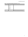
The desktop board supports single channel memory configurations defined in Table 4.
Table 4. Memory Support
Memory Speed Processor System Bus (MHz) Memory Speed Outcome (MHz)
Pentium 4 processor 533 333 DDR 333
Pentium 4 processor
or Celeron processor
400 266
Pentium 4 processor 533 or 400 266 DDR266
Celeron processor 400 266
DDR200 Pentium 4 processor
or Celeron processor
400 200
• Two 2.5 V 184-pin DDR DIMM sockets with gold-plated contacts
• Serial Presence Detect (SPD)
• Unbuffered, non-ECC RAM (registered memory is not supported)
• Support for 64 Mb, 128 Mb, 256 Mb, and 512 Mb memory technologies for the following
memory configurations:
— 64 MB to 256 MB utilizing 64 Mb technology
— Up to 512 MB utilizing 128 Mb technology
— Up to 1.0 GB utilizing 256 Mb technology
— Up to 2 GB utilizing 512 MB technology
Related Links:
Go to the following links or pages for more information about:
• The latest list of tested memory, http://support.intel.com/support/motherboards/desktop/
• SDRAM specifications, http://www.intel.com/technology/memory/pcsdram/spec/
• Installing memory, page 28 in Chapter 2

Desktop Board Features
15
Intel
®
845GV Chipset
The Intel 845GV chipset consists of the following:
• Intel 82845GV Graphics and Memory Controller Hub (GMCH) with AHA bus
• Intel 82801DB I/O Controller Hub (ICH4) with AHA bus
• Firmware Hub (FWH)
Related Link:
Go to the following link for more information about the Intel 845GV chipset:
http://developer.intel.com/design/nav/pcserver.htm
Audio Subsystem
The audio subsystem features the following:
• Intel 845GV chipset (AC ’97)
• Realtek ALC202A codec
The audio subsystem supports the following audio interfaces:
• ATAPI-style connectors:
— Auxiliary line in
— CD-ROM
• Front panel audio connector
• Back panel connectors:
— Line out
— Line in
— Mic in
✏
NOTE
The line out connector, located on the back panel, is designed to power either headphones or
amplified speakers only. Poor audio quality may occur if passive (non-amplified) speakers are
connected to this output.
Related Links:
Go to the following link or pages for more information about:
• Audio drivers and utilities, http://support.intel.com/support/motherboards/desktop/
• Installing a front panel audio solution, page 32 in Chapter 2

Intel Desktop Board D845GVSR Product Guide
16
LAN Subsystem (Optional)
The optional Intel 82562ET (with the Intel 82801DB ICH4) provides a Fast PCI LAN subsystem
providing both 10Base-T and 100Base-TX connectivity. The Intel 82562ET provides the
following functions:
• Basic 10/100 Ethernet LAN connectivity
• Support for RJ-45 connector with status indicator LEDs
• Programmable transit threshold
• Configurable EEPROM that contains the MAC address
LAN Subsystem Software
For LAN software and drivers, refer to the D845GVSR link on Intel’s World Wide Web site at:
http://support.intel.com/support/motherboards/desktop/
RJ-45 LAN Connector LEDs
Two LEDs are built into the RJ-45 LAN connector. Table 5 describes the LED states when the
desktop board is powered up and the LAN subsystem is operating.
Table 5. RJ-45 LAN Connector LEDs
LED Color LED State Indicates
Off 10 Mbit/sec data rate is selected. Green
On 100 Mbit/sec data rate is selected.
Off LAN link is not established.
On (steady state) LAN link is established.
Yellow
On (brighter and pulsing) The computer is communicating with another computer on
the LAN.
Hi-Speed USB 2.0 Support
✏
NOTE
Computer systems that have an unshielded cable attached to a USB port might not meet FCC
Class B requirements, even if no device or a low-speed USB device is attached to the cable. Use a
shielded cable that meets the requirements for a full-speed USB device.
This desktop board supports up to six USB 2.0 ports via ICH4; four ports routed to the back
panel and two routed to a USB front panel header. USB 2.0 ports are backward compatible with
USB 1.1 devices. USB 1.1 devices will function normally at USB 1.1 speeds.
Disabling Hi-Speed USB in the BIOS reverts all USB 2.0 ports to USB 1.1 operation. This may be
required to accommodate operating systems that do not support USB 2.0.

Desktop Board Features
17
Enhanced IDE Interface
The ICH4’s IDE interface handles the exchange of information between the processor and
peripheral devices like hard disks, CD-ROM drives, and Iomega Zip* drives inside the computer.
The interface supports:
• Up to four IDE devices (such as hard drives)
• ATAPI devices (such as CD-ROM drives)
• Older PIO Mode devices
• Ultra DMA-33 and ATA-66/100 protocols
• Laser Servo (LS-120) drives
Expansion Slots
Desktop Board D845GVSR has three PCI bus add-in card connectors.
BIOS
The BIOS provides the Power-On Self-Test (POST), the BIOS Setup program, the PCI and IDE
auto-configuration utilities, and the video BIOS. The BIOS is stored in the firmware hub.
The BIOS can be updated by following the instructions in Chapter 3 on page 45.
PCI Auto Configuration
If you install a PCI add-in card in your computer, the PCI auto-configuration utility in the BIOS
automatically detects and configures the resources (IRQs, DMA channels, and I/O space) for that
add-in card. You do not need to run the BIOS Setup program after you install a PCI add-in card.
IDE Auto Configuration
If you install an IDE device (such as a hard drive) in your computer, the IDE auto-configuration
utility in the BIOS automatically detects and configures the device for your computer. You do not
need to run the BIOS Setup program after installing an IDE device. You can override the
auto-configuration options by specifying manual configuration in the BIOS Setup program.
To use ATA-66/100 features, the following items are required:
• An ATA-66/100 peripheral device
• An ATA-66/100 compatible cable
• ATA-66/100 operating system device drivers

Intel Desktop Board D845GVSR Product Guide
18
Security Passwords
The BIOS includes security features that restrict whether the BIOS Setup program can be accessed
and who can boot the computer. A supervisor password and a user password can be set for the
Setup and for booting the computer, with the following restrictions:
• The supervisor password gives unrestricted access to view and change all Setup options. If
only the supervisor password is set, pressing <Enter> at the password prompt of Setup gives
the user restricted access to Setup.
• If both the supervisor and user passwords are set, you must enter either the supervisor
password or the user password to access Setup. Setup options are then available for viewing
and changing depending on whether the supervisor or user password was entered.
• Setting a user password restricts who can boot the computer. The password prompt is
displayed before the computer is booted. If only the supervisor password is set, the computer
boots without asking for a password. If both passwords are set, you can enter either password
to boot the computer.
Power Management Features
• Advanced Configuration and Power Interface (ACPI)
• Hardware support:
— Power connectors
— Fan connectors
— Chassis intrusion
— Suspend to RAM (Instantly Available PC technology)
— Wake from USB
— Wake from PS/2 keyboard/mouse
— PME# wakeup support
ACPI
ACPI gives the operating system direct control over the power management and Plug & Play
functions of a computer. The use of ACPI with the desktop board requires an operating system
that provides full ACPI support.
Power Connectors
The desktop board has two power connectors. See Figure 10 on page 34 for the location of the
power connectors.
Fan Connectors
The desktop board has two chassis fan headers and one processor fan header. See Figure 10 on
page 34 for the location of the fan headers.

Desktop Board Features
19
Chassis Intrusion
The board supports a chassis security feature that detects if the chassis cover has been removed.
The security feature uses a mechanical switch on the chassis that can be connected to the chassis
intrusion header on the desktop board. See Figure 10 on page 34 for the location of the chassis
intrusion header.
Suspend to RAM (Instantly Available PC Technology)
CAUTION
For Instantly Available PC technology, the 5 V standby line for the power supply must be capable
of delivering adequate +5 V standby current. Failure to provide adequate standby current when
using this feature can damage the power supply and/or effect ACPI S3 sleep state functionality.
Instantly Available PC technology enables the board to enter the ACPI S3 (Suspend-to-RAM)
sleep state. While in the S3 sleep state, the computer will appear to be off. When signaled by a
wake-up device or event, the system quickly returns to its last known awake state.
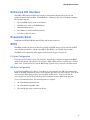
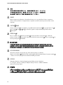
The desktop board’s standby power indicator, shown in Figure 2, is lit when there is standby power
to the system. This includes the memory modules and PCI bus connectors, even when the
computer appears to be off.
If the system has a dual-colored power LED on the front panel, the sleep state is indicated by the
LED turning amber.
OM16273
Figure 2. Location of Standby Power Indicator
CAUTION
Power supplies used with this desktop board must be able to provide enough standby current to
support the standard Instantly Available (ACPI S3 sleep state) configuration. If the standby
current necessary to support multiple wake events from the PCI and/or USB buses exceeds power
supply capacity, the desktop board may lose register settings stored in memory.
Related Links:
For more information on standby current requirements, navigate to the TPS by first selecting the
desktop board from the following link:
http://support.intel.com/support/motherboards/desktop/

Intel Desktop Board D845GVSR Product Guide
20
Wake from USB
USB bus activity wakes the computer from an ACPI S1 or S3 state.
NOTE
Wake from USB requires the use of a USB peripheral that supports Wake from USB.
Wake from PS/2 Keyboard/Mouse
PS/2 keyboard/mouse activity wakes the computer from an ACPI S1 or S3 state.
PME# Wakeup Support
When the PME# signal on the PCI bus is asserted, the computer wakes from an ACPI S1, S3, or
S5 state.
Speaker
A speaker is mounted on the desktop board. The speaker provides audible error code (beep code)
information during the Power-On Self-Test (POST).
Battery
A battery on the desktop board keeps the values in CMOS RAM and the clock current when the
computer is turned off. See Chapter 2 starting on page 21 for instructions on how to replace the
battery.
Real-Time Clock
The desktop board has a time-of-day clock and 100-year calendar. The battery on the desktop
board keeps the clock current when the computer is turned off.
La pagina si sta caricando...
La pagina si sta caricando...
La pagina si sta caricando...
La pagina si sta caricando...
La pagina si sta caricando...
La pagina si sta caricando...
La pagina si sta caricando...
La pagina si sta caricando...
La pagina si sta caricando...
La pagina si sta caricando...
La pagina si sta caricando...
La pagina si sta caricando...
La pagina si sta caricando...
La pagina si sta caricando...
La pagina si sta caricando...
La pagina si sta caricando...
La pagina si sta caricando...
La pagina si sta caricando...
La pagina si sta caricando...
La pagina si sta caricando...
La pagina si sta caricando...
La pagina si sta caricando...
La pagina si sta caricando...
La pagina si sta caricando...
La pagina si sta caricando...
La pagina si sta caricando...
La pagina si sta caricando...
La pagina si sta caricando...
La pagina si sta caricando...
La pagina si sta caricando...
La pagina si sta caricando...
La pagina si sta caricando...
La pagina si sta caricando...
La pagina si sta caricando...
La pagina si sta caricando...
La pagina si sta caricando...
La pagina si sta caricando...
La pagina si sta caricando...
La pagina si sta caricando...
La pagina si sta caricando...
La pagina si sta caricando...
La pagina si sta caricando...
La pagina si sta caricando...
La pagina si sta caricando...
La pagina si sta caricando...
La pagina si sta caricando...
La pagina si sta caricando...
La pagina si sta caricando...
La pagina si sta caricando...
La pagina si sta caricando...
La pagina si sta caricando...
La pagina si sta caricando...
La pagina si sta caricando...
La pagina si sta caricando...
La pagina si sta caricando...
La pagina si sta caricando...
La pagina si sta caricando...
La pagina si sta caricando...
La pagina si sta caricando...
La pagina si sta caricando...
La pagina si sta caricando...
La pagina si sta caricando...
La pagina si sta caricando...
La pagina si sta caricando...
-
 1
1
-
 2
2
-
 3
3
-
 4
4
-
 5
5
-
 6
6
-
 7
7
-
 8
8
-
 9
9
-
 10
10
-
 11
11
-
 12
12
-
 13
13
-
 14
14
-
 15
15
-
 16
16
-
 17
17
-
 18
18
-
 19
19
-
 20
20
-
 21
21
-
 22
22
-
 23
23
-
 24
24
-
 25
25
-
 26
26
-
 27
27
-
 28
28
-
 29
29
-
 30
30
-
 31
31
-
 32
32
-
 33
33
-
 34
34
-
 35
35
-
 36
36
-
 37
37
-
 38
38
-
 39
39
-
 40
40
-
 41
41
-
 42
42
-
 43
43
-
 44
44
-
 45
45
-
 46
46
-
 47
47
-
 48
48
-
 49
49
-
 50
50
-
 51
51
-
 52
52
-
 53
53
-
 54
54
-
 55
55
-
 56
56
-
 57
57
-
 58
58
-
 59
59
-
 60
60
-
 61
61
-
 62
62
-
 63
63
-
 64
64
-
 65
65
-
 66
66
-
 67
67
-
 68
68
-
 69
69
-
 70
70
-
 71
71
-
 72
72
-
 73
73
-
 74
74
-
 75
75
-
 76
76
-
 77
77
-
 78
78
-
 79
79
-
 80
80
-
 81
81
-
 82
82
-
 83
83
-
 84
84


eMachines D845GVSR Manuale utente
- Categoria
- Schede madri
- Tipo
- Manuale utente
- Questo manuale è adatto anche per
in altre lingue
- English: eMachines D845GVSR User manual
Altri documenti
-
Intel D945PVS Manuale utente
-
-
-
-
-
-
-
-
-
Intel BOXD945PSNLK Manuale utente