
Code 1.040879 - Rev. ST.003084/002
IT
Generalità.
L’intubamento è un’operazione attraverso la quale, nell’ambito
della ristrutturazione di un sistema e mediante l’introduzione
di uno o più appositi condotti, si realizza un sistema nuovo per
l’evacuazione dei prodotti della combustione di un apparecchio
a gas, a partire da un camino esistente (o da una canna fuma-
ria) o da un’asola tecnica. Il sistema di intubamento essibile Ø
80 deve essere utilizzato solo per uso domestico e con caldaie a
condensazione Immergas secondo le congurazioni menzionate
nei libretti istruzioni di caldaia (es.:C53; C93).
In ogni caso, le operazioni di intubamento devono rispettare
le prescrizioni contenute nella normativa e nella legislazione
tecnica vigente (UNI 7129-3:2015); in particolare, al termine
dei lavori ed in corrispondenza della messa in servizio del
sistema intubato, dovrà essere compilata la dichiarazione di
conformità. Dovranno altresì essere seguite le indicazioni
del progetto o della relazione tecnica, nei casi previsti dalla
normativa vigente. Per garantire adabilità e funzionalità nel
tempo del sistema è necessario che:
- sia utilizzato in condizioni atmosferiche ed ambientali
medie, come denite dalla normativa vigente (assenza di
fumi, polveri o gas atti ad alterare le normali condizioni ter-
mosiche o chimiche; sussistenza di temperature comprese
nell’intervallo standard di variazione giornaliera, ecc.).
- L’installazione e la manutenzione siano eettuate secondo le
indicazioni fornite dal costruttore e secondo le prescrizioni
della normativa vigente.
Composizione.
Il sistema per intubamento essibile Ø 80 Immergas è com-
posto da una serie di moduli e di componenti, identicati
come singoli kit, che, assemblati secondo le speciche esigenze
installative, costituiscono il sistema completo e ne consentono
l’abbinamento con le varie soluzioni impiantistiche:
3.027873 - Kit staa sostegno curva Ø 80 mm 87° e adattatore
essibile Ø 80
3.027874 - Kit staa sostegno curva Ø 80 mm 70° M e adat-
tatore essibile Ø 80
3.027875 - Kit tubo essibile Ø 80 12 m con distanziali
3.027876 - Kit terminale vert. Ø 80/125 per fumisteria es-
sibile Ø 80 (C + C)
3.027877 - Kit adattatore essibile/essibile per fumisteria
essibile Ø 80
3.022033 - Kit intubamento C9 Ø125
3.012008 - Kit pannello di chiusura foro camino
SISTEMA INTUBAMENTO FLESSIBILE Φ80
CAMINI /CANNE FUMARIE
PER CALDAIE A CONDENSAZIONE
Generalities.
Ducting is an operation through which, within the context
of restructuring a system and with the introduction of one or
more special ducts, a new system is executed for evacuating
the combustion products of a gas appliance, starting from an
existing ue (or a chimney) or a technical slot. e 80 Ø exi-
ble ducting system must only be used for domestic use and with
Immergas condensation boilers, according to the congurations
mentioned in the boiler’s instruction booklets (e.g.: C53; C93).
In any case, ducting operations must respect the provisions
contained in the standard and in current technical regulations;
in particular, the declaration of conformity must be compiled
at the end of work and on commissioning of the ducted sys-
tem. e instructions in the project or technical report must
likewise be followed, in cases provided for by the current regu-
lations. To guarantee system reliability and duration, you must:
- it is used in average atmospheric and environmental
conditions, according to current regulations (absence of
combustion products, dusts or gases that can alter the
normal thermophysical or chemical conditions; existence
of temperatures coming within the standard range of daily
variation, etc.).
- Installation and maintenance must be performed accord-
ing to the indications supplied by the manufacturer and in
compliance with the provisions in force.
Composition.
e Ø 80 Immergas exible ducting system consists of a series
of modules and components, identied as individual kits,
which, assembled according to specic installation needs,
make up the complete system and enable it to be combined
with the various know plant solutions:
3.027873 - Support bend kit Ø 80 87° and exible ducting
adapter Ø 80
3.027874 - Support bend kit Ø 80 70° M and exible ducting
adapter Ø 80
3.027875 - Flexible duct kit Ø 80 12m with spacers
3.027876 - Vertical outlet kit Ø 80/125 for exible ducting
Ø 80
3.027877 - Flexible/exible adapter kit for exible ducting
Ø 80
3.022033 - Ø 125 ducting kit for C9
3.012008 - Chimney hole closure panel kit
Φ80 FLEXIBLE CHIMNEYS DUCTING
SYSTEM / FLUES FOR CONDENSATION
BOILERS
IE

1
2
3
5
2
4
5
6
5
4
3
1
4
3
3
4
5
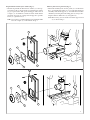
Installation.
• Preparation of masonry, eliminating the brickwork chimney
cap at the top of the chimney.
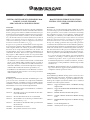
Flexible hose kit Ø 80 mm, L = 12 m (Fig. 1).
• Lower the pipe (1) into the ue, remembering to insert a
centring spacer consisting of 2 semi-collars with aps (2)
every now and again (at least every 2 m), which allow the
pipe to stay in the centre of the ue.
Flexible/exible adapter kit for exible ue extraction ele-
ments Ø 80 (Fig. 1).
In case you wish to recover a exible hose le over from
another installation, it can be joined to other pieces via the
exible/exible adapter (6), paying attention to assemble it
as described below:
• In order, insert the ring nut (3), the collar (4) and then the
gasket (5) on the exible hose (1), as shown in Fig. 1.
• Tighten the ring nut (3) with exible hose (1) onto the
adapter (6) to the end stop.
Vertical outlet kit Ø 80/125 for exible ue extraction ele-
ments Ø 80 (C5 + C9) (Fig. 2).
• Secure the valley gutter unit (7) to the chimney using the
most suitable method, according to the technical standard
and conditions of the chimney itself, making the exible
hose (4) come out from the top.
• In order, insert the ring nut (1), the collar (2) and then the
gasket (3) on the exible hose (4), as shown in Fig. 2.
• Tighten the ring nut (1) with exible hose (4) onto the
adapter (5) to the end stop.
• Aer ensuring the gasket (6) is there, couple the exible/
rigid adapter (5) onto the exhaust grid outlet (8), which in
turn is to be coupled onto the valley gutter unit (7).
1
Installazione.
• Predisporre le opere murarie eliminando il comignolo in
muratura alla sommità del camino.
Kit tubo essibile Ø 80 mm, L = 12 m (Fig. 1).
• Calare il tubo (1), nella canna fumaria ricordandosi di in-
serire di tanto in tanto (almeno ogni 2 m) un distanziale di
centraggio costituito da 2 semicollari provvisti di linguette
(2) per permettere al tubo di mantenere il centro della canna
fumaria.
Kit adattatore essibile/essibile per fumisteria essibile
Ø 80 (Fig. 1).
Nel caso in cui si volesse recuperare un pezzo di tubo essibile
rimasto da un’altra installazione, è possibile unirlo con altri
pezzi mediante l’adattatore essibile/essibile (6) prestando
attenzione ad assemblarlo come descritto di seguito:
• Inserire nell’ordine la ghiera (3), il collare (4) e la guarnizione
(5) sul tubo essibile (1) come indicato in Fig. 1.
• Avvitare la ghiera (3) provvista di tubo essibile (1) sull’a-
dattatore (6) no in battuta.
Kit terminale verticale Ø 80/125 per fumisteria essibile Ø 80
(C + C) (Fig. 2).
• Fissare il gruppo conversa (7) al camino utilizzando il
metodo più adatto a seconda della buona tecnica e delle
condizioni del camino stesso, facendo fuoriuscire dalla
sommità il tubo essibile (4).
• Inserire nell’ordine la ghiera (1), il collare (2) e la guarnizione
(3) sul tubo essibile (4) come indicato in Fig. 2.
• Avvitare la ghiera (1) provvista di tubo essibile (4) sull’a-
dattatore (5) no in battuta.
• Dopo aver vericato la presenza della guarnizione (6), inse-
rire l’adattatore essibile/rigido (5) sul terminale di scarico
grigliato (8) e quest’ultimo sul gruppo conversa (7).
2
7
4
1
3
2
6
5
8
1
2
3

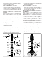
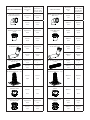
e following support bracket kits can be installed, depend-
ing on your needs:
- Support bracket bend kit Ø 80 mm 87° and exible adap-
ter Ø 80 (Fig. 3)
or
- Support bracket bend kit Ø 80 mm 70° M and exible
adapter Ø 80 (Fig. 4) shown on the next page.
Support bracket bend kit Ø 80 mm 87° for exible ue ex-
traction elements Ø 80 (Fig. 3).
• Create an opening of about 160 x 330 mm, as indicated
in gure 3, checking the height of the boiler ue channel
from the ground in order to determine the centre of the
bend support (2). Respect the height of 70 mm to start the
opening in order to ensure the metal bracket (1) is properly
supported.
• Install the metal bracket (1) making a Ø 10 mm hole at a
distance of 70 mm from the centre of the bend; insert it and
cut o the excess part indicated by the arrow, as illustrated
in gure 3.
• Fix the bend support (2) Ø 80 mm M/F at 87°, centring it
with respect to the ue (insert the lower pin (3) of the bend
in the most suitable hole of the previously installed support
metal bracket (1)).
• Insert the Ø 80 adapter (4) into the support bend (2) to the
end stop (approximately 50 mm), making sure the gasket
(5) is there.
• In order, insert the ring nut (6), the collar (7) and then the
gasket (8) on the exible hose (9), as shown in Fig. 3.
• Tighten the ring nut (6) with exible hose (9) onto the
adapter (4) to the end stop.
E’ possibile, a seconda delle necessità, installare i seguenti
kit staa di sostegno:
- Kit staa sostegno curva Ø 80 mm 87° e adattatore es-
sibile Ø 80 (Fig. 3)
oppure
- Kit staa sostegno curva Ø 80 mm 70° M e adattatore
essibile Ø 80 (Fig. 4) riportato alla pagina successiva.
Kit staa sostegno curva Ø 80 mm 87° per fumisteria essibile
Ø 80 (Fig. 3).
• Creare una apertura di circa 160 x 330 mm come indicato
in gura 3, vericando l’altezza da terra del canale da fumo
della caldaia per determinare il centro della curva di soste-
gno (2). Rispettare tassativamente la quota di 70 mm per
iniziare l’apertura, in modo da garantire l’appoggio della
staa metallica di sostegno (1).
• Installare la staa metallica di sostegno (1) praticando un
foro Ø 10 mm ad una distanza di 70 mm dal centro curva;
inserire la medesima e tagliare la parte in eccedenza indicata
dalla freccia come illustrato nella gura 3.
• Fissare la curva di sostegno (2) Ø 80 mm M/F a 87° cen-
trandola rispetto la canna fumaria (inlare il perno inferiore
(3) della curva nel foro più idoneo della staa metallica di
sostegno (1) precedentemente installata).
• Innestare l’adattatore Ø 80 (4) nella curva di sostegno (2)
no a battuta (circa 50 mm) assicurandosi della presenza
della guarnizione (5).
• Inserire nell’ordine la ghiera (6), il collare (7) e la guarnizione
(8) sul tubo essibile (9) come indicato in Fig. 3.
• Avvitare la ghiera (6) provvista di tubo essibile (9) sull’a-
dattatore (4) no in battuta.
3
1
2
3
5
4
6
7
8
9
8
6
7
X
X:2
330 (*)
70
=
=
160 (*)
(*) misure indicative
(*) indicative measurements

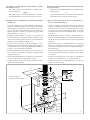
Support bracket bend kit Ø 80 mm 70° M for exible ue
extraction elements Ø 80 (Fig. 4).
• Create an opening of about 140 x 220 mm, as shown in gure
4/A. Respect the maximum wall thickness of 100 mm and
the minimum chimney dimension of 140 mm.
• Open the 4 clamping ns (1) on the support bracket bend
(2) and position it at the opening of the chimney, as shown
in g. 4/B.
• Drill the chimney with a Ø 5 drill bit and secure the bracket
(2) with the 4 wall plugs (3) provided.
• Pull about 200 mm of exible hose (4) out of the chimney
opening (g. 4/A).
• In order, insert the ring nut (5), the collar (6) and then the
gasket (7) on the exible hose (4), as shown in g. 4/C.
• Tighten the ring nut (5) with exible hose (4) onto the 70°
bend (8) to the end stop (g. 4/C).
• Insert the bend (8) with exible hose (4) into the bracket
(2), as shown in g. 4/D.
• Block the bend (8) onto the bracket (2) at the required di-
stance by inserting the pin (9) into one of the holes (10) on
the bracket (2), as shown in g. 4/D.
Kit staa sostegno curva Ø 80 mm 70° M per fumisteria
essibile Ø 80 (Fig. 4).
• Creare un’ apertura di circa 140 x 220 mm come indicato in
gura 4/A. Rispettare tassativamente le quote dello spessore
massimo muro 100 mm e dimensione minima camino di
140 mm.
• Aprire le 4 alette di ssaggio (1) della staa supporto curva
(2) e posizionarla in corrispondenza dell’apertura del camino
come indicato in g. 4/B.
• Forare il camino con una punta Ø 5 e ssare la staa (2) con
4 tasselli (3) forniti in dotazione.
• Far fuoriuscire circa 200 mm di tubo essibile (4) dall’aper-
tura del camino (g. 4/A).
• Inserire nell’ordine la ghiera (5), il collare (6) e la guarnizione
(7) sul tubo essibile (4) come indicato in g. 4/C.
• Avvitare la ghiera (5) provvista di tubo essibile (4) sulla
curva 70° (8) no in battuta (g. 4/C).
• Inlare la curva (8) provvista di tubo essibile (4) all’interno
della staa (2) come indicato in g. 4/D.
• Bloccare la curva (8) sulla staa (2) alla distanza desiderata
inserendo il perno (9) in uno dei fori predisposti (10) sulla
staa (2) come indicato in g. 4/D.
4
(*) indicative measurements
(*) misure indicative
2
3
220 (*)
min.140
max.100 2
4
3
1
1
1
200 (*)
140 (*)
7
6
8
5
5
4
6
7
2
4
8
8
CLICK
9
9
10
C
AB
D

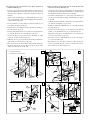
Chimney hole closure panel kit (Fig. 5).
• Mount the chimney hole closure panel (1) as indicated in
g. 5, positioning the gasket (2) to cover the hole made for
assembly of the bend support (3). Assemble the boiler ue
channel by inserting the wall sealing plate (4) and positio-
ning the relative drilled door (5) and gasket (6).
Note: If necessary, you can cut the end of the support bend
(3) as shown in g. 5.
Kit pannello di chiusura foro camino (Fig. 5 ).
• Montare il pannello di chiusura foro camino (1) come rap-
presentato in g. 5, interponendo la guarnizione di tenuta
(2) per coprire il foro fatto per il montaggio della curva di
sostegno (3). Assemblare il canale da fumo della caldaia
inserendo il rosone (4) e interponendo l’apposito sportello
forato (5) e guarnizione (6).
N.B. Se necessario è possibile tagliare la parte terminale della
curva di sostegno (3) come indicato in g. 5.
5
1
2
3
4
6
5
1
2
3
4
6
5

Installation regulations.
e Ø 80 exible ducting system must be coupled exc lusively
to Immergas sealed chamber, fan assisted boilers operating with
condensation system.
e installation of the support metal bracket (1 Fig. 3) or (2
Fig. 4) on the wall must ensure a stable and eective mount to
the system itself (therefore, compliance with the measurements
indicated in the installation chapter is recommended, to give
it a rm masonry support).
• Resistance factors and equivalent lengths. Each ue com-
ponent has a resistance factor based on experimental tests
and specied in the following table. e resistance factor
for individual components is independent from the type
of boiler on which it is installed and has a dimensionless
size. It is however, conditioned by the temperature and the
mass of the uids that pass through the pipe and therefore,
varies according to applications for air intake or ue exhaust.
Each single component has a resistance corresponding to a
certain length in metres of pipe of the same diameter; the
so-called equivalent length, obtained from the ratio between
the relative resistance factors. Example: support bend Ø 80
mm M/F at 87° - resistance factor in exhaust 2.55; exible
hose Ø 80 mm (m 1) - resistance factor in exhaust 4.47;
equivalent length of the bend support Ø 80 mm M/F at 87°
= 2.55 : 4.47 = 0.57 m of exible hose Ø 80 mm in exhaust.
All boilers have an experimentally obtainable maximum re-
sistance factor equal to 100. e maximum resistance factor
allowed corresponds to the resistance encountered with the
maximum allowed pipe length for each type of Terminal Kit.
is information allows calculations to be made to verify
the possibility of setting up various ue congurations.
Maintenance.
• Routine maintenance. To be carried out according to the
instructions in the boiler’s booklet.
• Extraordinary maintenance. is type of maintenance re-
quires a check of the ducting system for leaks in the following
cases: (See following paragraph):
- accidental events which may have changed or jeopardised
the correct operation of system uid dynamics;
- building interventions that may adversely aect or change
the correct operation of system uid dynamics;
- according to the laws in force, replacement of equipment
with other similar Immergas condensation equipment;
- whenever the system is non-functional and not adaptable
under the regulations in force.
Check of the ducting system sealing.
e duct sealing system check must be carried out aer instal-
lation, in accordance with what is specied into the National
Standard.
Should extraordinary maintenance be requested, the sealing
system must be checked according to National Standard.
e results of the checks must be reported in the documen-
tation provided by the laws in force (e.g. declaration of con-
formity). Failure to carry out this check and if the sealing limit
specied in the standard is not observed, the system warranty
and the manufacturer’s responsibility shall be void.
Norme di installazione.
Il sistema di intubamento essibile Ø 80 deve essere abbinato
esclusivamente a caldaie Immergas a camera stagna e tiraggio
forzato funzionanti con sistema a condensazione.
L’installazione della staa metallica di sostegno (1 Fig. 3) o
(2 Fig. 4) sulla parete, deve garantire un supporto stabile ed
ecace al sistema stesso (si raccomanda pertanto il rispetto
delle misure indicate nel capitolo di installazione, per dare un
appoggio stabile di muratura alla medesima).
• Fattori di resistenza e lunghezze equivalenti. Ogni compo-
nente della fumisteria ha un fattore di resistenza ricavato
da prove sperimentali e riportato nella tabella riportata di
seguito. Il fattore di resistenza del singolo componente è
indipendente dal tipo di caldaia su cui viene installato ed
è una grandezza adimensionale. Esso è invece condizion-
ato dalla temperatura e dalla massa dei uidi che passano
all’interno del condotto e pertanto varia con l’impiego in
aspirazione aria o in scarico fumi. Ogni singolo componente
ha una resistenza corrispondente a una certa lunghezza in
metri di tubo dello stesso diametro; la cosiddetta lunghezza
equivalente, ricavabile dal rapporto fra i relativi fattori di
resistenza, ad esempio: curva di sostegno Ø 80 mm M/F a
87° - fattore di resistenza in scarico 2,55; tubo essibile Ø 80
mm (m 1) - fattore resistenza in scarico 4,47; lunghezza
equivalente curva di sostegno Ø 80 mm M/F a 87° = 2,55 :
4,47 = 0,57 m di tubo essibile Ø 80 mm in scarico. Tutte
le caldaie hanno un fattore di resistenza massimo ricavabile
sperimentalmente uguale a 100. Il fattore di resistenza mas-
simo ammissibile corrisponde alla resistenza riscontrata con
la massima lunghezza ammissibile di tubi con ogni tipologia
di Kit Terminale. L’insieme di queste informazioni consente
di eettuare i calcoli per vericare la possibilità di realizzare
le più svariate congurazioni di fumisteria.
Manutenzione.
• Manutenzione ordinaria. Da eettuare secondo le modalità
riportate nel libretto istruzioni della caldaia.
• Manutenzione straordinaria. Tale tipo di manutenzione
richiede la verica della tenuta del sistema nei seguenti casi:
(Vedi paragrafo seguente):
- eventi di tipo accidentale che possono aver modicato o compro-
messo il corretto funzionamento uidodinamico del sistema;
- interventi di tipo edilizio che potrebbero compromettere o mo-
dicare il corretto funzionamento uidodinamico del sistema;
- sostituzione di apparecchi, nel rispetto delle norme vigenti,
con altri apparecchi a condensazione Immergas similari;
- ogni qualvolta il sistema risulti non funzionale e non ade-
guabile ai sensi della norma vigente.
Verica della tenuta del sistema intubamento.
La verica di tenuta del sistema intubato, quando espressamen-
te previsto dalla norma UNI 7129:2015, deve essere eettuata
al termine dell’installazione, in accordo a quanto specicato
dalla norma stessa.
Nel caso di manutenzione straordinaria, qualora richiesta, la
verica di tenuta deve essere eettuata secondo la UNI 10845.
Gli esiti delle veriche dovranno essere riportati sulla docu-
mentazione prevista dalla legislazione vigente (es.: dichiara-
zione di conformità). In mancanza di tale verica e nel caso
in cui non venga rispettato il limite di tenuta specicato dalla
norma decadrà la garanzia del sistema e la responsabilità del
costruttore.

TYPE OF DUCT
Resistance
Factor
(R)
Equivalent len-
gth in metres
of Ø 80 mm
exible hose
Bend support Ø 80 mm
M/F at 87° Intake
1,87
Intake
0,59
Exhaust
2,55
Exhaust
0,57
Ø 80 M exible
adapter
Intake
0,43
Intake
0,13
Exhaust
0,60
Exhaust
0,13
Bend support
Ø 80 mm at 70° Intake
2,94
Intake
0,92
Exhaust
4,11
Exhaust
0,92
Ø 80 mm exible hose
(1 m) Intake
3,19
Intake
1
Exhaust
4,47
Exhaust
1
Vertical terminal
Ø 80/125 mm (C5 - C9)
Exhaust
3,04
Exhaust
0,68
Ø 80 Flexible adapter
female
Exhaust
0,77
Exhaust
0,17
Ø 80 Flexible/exible
adapter Intake
0,98
Intake
0,3
Exhaust
1,37
Exhaust
0,31
TIPO DI CONDOTTO
Fattore di
Resistenza
(R)
Lunghezza
equivalente in
metri di tubo
essibile Ø 80
Curva di sostegno
Ø 80 mm M/F a 87° Aspirazione
1,87
Aspirazione
0,59
Scarico
2,55
Scarico
0,57
Adattatore M essibile
Ø 80
Aspirazione
0,43
Aspirazione
0,13
Scarico
0,60
Scarico
0,13
Curva di sostegno
Ø 80 mm a 70° Aspirazione
2,94
Aspirazione
0,92
Scarico
4,11
Scarico
0,92
Tubo essibile Ø 80
mm (1 m) Aspirazione
3,19
Aspirazione
1
Scarico
4,47
Scarico
1
Terminale verticale
Ø 80/125 mm (C5 - C9)
Scarico
3,04
Scarico
0,68
Adattatore essibile
femmina Ø 80
Scarico
0,77
Scarico
0,17
Adattatore essibile/
essibile Ø 80 Aspirazione
0,98
Aspirazione
0,3
Scarico
1,37
Scarico
0,31

N.B.: L’estensione massima di 18 m circa in scarico di tubo
corrugato Ø 80 mm essibile,valida per la maggior parte delle
caldaie, è ottenibile con la seguente congurazione:
- aspirazione con 1 m di tubo rigido Ø 80 mm con griglia +
curva Ø 80 mm a 87° e relativo adattatore su caldaia;
- scarico con curva Ø 80 mm a 87° con relativo adattatore di
caldaia + 1 m di tubo Ø 80 mm rigido da collegare al cavedio;
- utilizzo del terminale C9 Ø 80/125 mm.
Il fattore di resistenza massimo pari a “100” non è superabile
in quanto la Caldaia andrebbe ad abbassare la sua Pn
( Potenza Nominale ) oltre la soglia minima di omologazione.
Importante: In ogni caso consultare lo specico libretto
istruzioni di caldaia.
Note: e maximum extension of about 18 metres in exhaust
of the Ø 80 mm exible corrugated pipe, valid for most boilers,
is available with the following conguration:
- intake with 1 m rigid pipe Ø 80 mm with grid + bend Ø 80
mm at 87° and its adapter on boiler;
- exhaust with bend Ø 80 mm at 87° with its boiler adaptor +
1 m rigid pipe Ø 80 mm to be linked to the sha;
- use of the terminal C9 Ø 80/125 mm.
e maximum resistance factor equal to “100” is not surmountable
because the Boiler would lower its Pn
( Nominal Output ) beyond the minimum threshold for approval.
Important: In any case, refer to the specic boiler instruc-
tion booklet.
-
 1
1
-
 2
2
-
 3
3
-
 4
4
-
 5
5
-
 6
6
-
 7
7
-
 8
8


in altre lingue
- English: Immergas ST008 User manual
Documenti correlati
Altri documenti
-
Wolf E Series Installation Instructions Manual
-
Carel GASTEAM Manuale utente
-
Ariston Clas 24 FF Scheda dati
-
BALTUR TBL 35 P 60Hz Use and Maintenance Manual
-
Ferroli KALIS 24 C – 34 C Caldera Bluehelix Hitech RRT Guida d'installazione
-
 Fer FERtech F 32 D Instructions For Use, Installation And Maintenance
-
-
Groupe Brandt DHD497XE1 Manuale del proprietario
-
