Delphi YDT262 Operating And Servicing Manual
- Tipo
- Operating And Servicing Manual

HL018, Issue 2
YDT262
Dynamic Timing Control Box
(GB) Operating and Servicing Manual
(F) Manuel d’Utilisation et d’Entretien
(D) Bedienungs- und Wartungshandbuch
(E) Manual de Funcionamiento y Servicio
(I) Manuale di Utilizzo e Manutenzione
(P) Manual de Funcionamento e Manutencao
THIS IS AN UNCONTROLLED DOCUMENT downloaded by Lukas Matuska on 16 Feb 2016
Any technical intervention requires certified Hartridge training. Contact Hartridge Ltd for details.

YDT262 Operating and Servicing Manual DELPHI DIESEL AFTERMARKET
2 HL018, Issue 2
THIS IS AN UNCONTROLLED DOCUMENT downloaded by Lukas Matuska on 16 Feb 2016
Any technical intervention requires certified Hartridge training. Contact Hartridge Ltd for details.

DELPHI DIESEL AFTERMARKET YDT262 Operating and Servicing Manual
HL018, Issue 2 3
CONTENTS / TABLE DES MATIERES /
INHALTSVERZEICHNIS / INDICE
ENGLISH _______________________________________________________________________________ 5
FOREWORD _____________________________________________________________________________ 5
1. INTRODUCTION ______________________________________________________________________ 6
2. DEFINITION OF TERMS AND ABBREVIATIONS _______________________________________________ 6
3. PRINCIPLE OF OPERATION ______________________________________________________________ 6
4. OPERATION _________________________________________________________________________ 7
4.1 Layout ___________________________________________________________________________ 7
4.2 Installation ________________________________________________________________________ 7
4.3 Software Operating Sequence _________________________________________________________ 8
4.4 Setting / Overchecking the Timing Position _______________________________________________ 9
4.5 Downloading an Alternate Language ___________________________________________________ 9
5. SPARES AND SERVICE ________________________________________________________________ 11
5.1 YDT262 Spares ___________________________________________________________________ 11
5.2 Related Parts/Tools ________________________________________________________________ 11
5.3 Troubleshooting ___________________________________________________________________ 11
FRANCAIS _____________________________________________________________________________ 13
AVANT-PROPOS ________________________________________________________________________ 13
1. INTRODUCTION _____________________________________________________________________ 14
2. DÉFINITION DES EXPRESSIONS ET ABRÉVIATIONS ___________________________________________ 14
3. PRINCIPLE DE FONCTIONNEMENT _______________________________________________________ 14
4. FONCTIONNEMENT __________________________________________________________________ 15
4.1 Agencement ______________________________________________________________________ 15
4.2 Installation _______________________________________________________________________ 15
4.3 Séquence d'utilisation du logiciel ______________________________________________________ 16
4.4 Réglage / Surcontrôle de la position de distribution _______________________________________ 17
4.5 Téléchargement d'une autre langue ____________________________________________________ 17
5. PIÈCES DE RECHANGE ET RÉPARATIONS __________________________________________________ 20
5.1 Pièces de rechange pour le YDT262 ___________________________________________________ 20
5.2 Pièces connexes/Outillages __________________________________________________________ 20
5.3 Dépistage des anomalies ____________________________________________________________ 20
DEUTSCH _____________________________________________________________________________ 21
VORWORT _____________________________________________________________________________ 21
1. EINFÜHRUNG ______________________________________________________________________ 22
2. DEFINITION VON BEZEICHNUNGEN UND ABKÜRZUNGEN _____________________________________ 22
3. BETRIEBSPRINZIP ___________________________________________________________________ 22
4. BETRIEB ____________________________________________________________________________ 23
4.1 Layout __________________________________________________________________________ 23
4.2 Montage _________________________________________________________________________ 24
4.3 Betriebsabfolge der Software _________________________________________________________ 24
4.4 Einstellung / Überprüfen der Timingposition ____________________________________________ 25
4.5 Herunterladen einer zusätzlichen Sprache _______________________________________________ 25
5. ERSATZTEILE UND KUNDENDIENST ________________________________________________________ 28
5.1 Ersatzteile für das YDT262 __________________________________________________________ 28
5.2 Dazugehörige Teile/Werkzeuge _______________________________________________________ 28
5.3 Fehlersuche ______________________________________________________________________ 28
ESPAÑOL ______________________________________________________________________________ 29
PREFACIO _____________________________________________________________________________ 29
1. INTRODUCCIÓN _____________________________________________________________________ 30
2. DEFINICIÓN DE TÉRMINOS Y ABREVIACIONES ______________________________________________ 30
3. PRINCIPIO DE FUNCIONAMIENTO ________________________________________________________ 30
4. FUNCIONAMIENTO ____________________________________________________________________ 31
THIS IS AN UNCONTROLLED DOCUMENT downloaded by Lukas Matuska on 16 Feb 2016
Any technical intervention requires certified Hartridge training. Contact Hartridge Ltd for details.

YDT262 Operating and Servicing Manual DELPHI DIESEL AFTERMARKET
4 HL018, Issue 2
4.1 Disposición ______________________________________________________________________ 31
4.2 Instalación _______________________________________________________________________ 31
4.3 Secuencia de funcionamiento del programa _____________________________________________ 32
4.4 Ajuste y verificación de las posiciones de tiempos ________________________________________ 33
4.5 Carga de un idioma alternativo ______________________________________________________ 33
5. REPUESTOS Y MANTENIMIENTO __________________________________________________________ 35
5.1 Repuestos para el controlador YDT262 ________________________________________________ 35
5.2 Componentes y herramientas auxiliares ________________________________________________ 35
5.3 Localización y solución de problemas _________________________________________________ 35
ITALIANO ____________________________________________________________________________ 37
1. INTRODUZIONE _____________________________________________________________________ 38
2. DEFINIZIONE DEI TERMINI E ABBREVIAZIONI ______________________________________________ 38
3. PRINCIPIO OPERATIVO _______________________________________________________________ 38
4. FUNZIONAMENTO _____________________________________________________________________ 39
4.1 Disposizione _____________________________________________________________________ 39
4.2 Installazione _____________________________________________________________________ 39
4.3 Sequenza operativa del Software _____________________________________________________ 40
4.4 Impostazione /Controllo della posizione di fasatura _______________________________________ 41
4.5 Trasferimento di una lingua alternativa ________________________________________________ 41
5. RICAMBI E ASSISTENZA ________________________________________________________________ 43
5.1 Ricambi YDT262 __________________________________________________________________ 43
5.2 Parti / Attrezzi ____________________________________________________________________ 43
5.3 Ricerca guasti ____________________________________________________________________ 43
PORTUGES ____________________________________________________________________________ 45
PREFÁCIO _____________________________________________________________________________ 45
1. INTRODUÇÃO ______________________________________________________________________ 46
2. DEFINIÇÃO DOS TERMOS E ABREVIATURAS _______________________________________________ 46
3. PRINCÍPIO DE FUNCIONAMENTO ________________________________________________________ 46
4. OPERAÇÃO __________________________________________________________________________ 47
4.1 Disposição _______________________________________________________________________ 47
4.2 Instalação _______________________________________________________________________ 48
4.3 Sequência Operacional do Software ___________________________________________________ 48
4.4 Regulação / Verificação da Posição de Ponto ___________________________________________ 49
4.5 Carregamento de outra Língua ______________________________________________________ 49
5. PEÇAS SOBRESSALENTES E SERVIÇO ______________________________________________________ 51
5.1 Peças sobressalentes YDT262 ________________________________________________________ 51
5.2 Peças/Ferramentas Relacionadas _____________________________________________________ 51
5.3 Solução de Problemas ______________________________________________________________ 51
THIS IS AN UNCONTROLLED DOCUMENT downloaded by Lukas Matuska on 16 Feb 2016
Any technical intervention requires certified Hartridge training. Contact Hartridge Ltd for details.

DELPHI DIESEL AFTERMARKET YDT262 Operating and Servicing Manual
HL018, Issue 2 5
ENGLISH
Foreword
Copyright
DT Assembly & Test - Europe Ltd. reserves the copyright of all information and illustrations in this
publication which is supplied in confidence and which may not be used for any other purpose other
than that for which it was originally supplied. The publication may not be reproduced in part or in
whole without the consent in writing of this company.
© DT Assembly & Test - Europe Ltd.
Safety Information
The YDT262 is used in conjunction with a host test bench. Basic safety rules and precautions for
operating the host test bench should be observed.
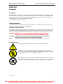
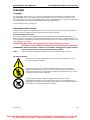
Warnings, Cautions and Notes
The precautionary notes in this publication, indicated by the words WARNING, CAUTION, or NOTE
provide information about potential hazards to personnel or equipment. Ignoring these notes may
lead to serious injury to personnel and/or damage to equipment. These notes appear as follows:
WARNING! INDICATES THAT A SITUATION MAY BE HAZARDOUS TO PERSONNEL.
INSTRUCTIONS ARE PROVIDED FOR AVOIDING PERSONAL INJURY.
CAUTION! Indicates that conditions exist that could result in damage to equipment.
Instructions are provided to prevent equipment damage.
NOTE Indicates additional information for clarification where there may be confusion.
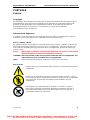
General Warnings
Ensure good levels of lighting for safe, efficient equipment operation.
Accidents can occur to unauthorised personnel during testing. Untrained
person(s) must not be present in the test area when the equipment is operating.
Only qualified personnel are to operate this equipment.
This equipment contains electrostatic sensitive devices. Observe the necessary
precautions for handling electrostatic discharge sensitive devices. Do not touch
printed circuit boards and associated electronic connections and components.
THIS IS AN UNCONTROLLED DOCUMENT downloaded by Lukas Matuska on 16 Feb 2016
Any technical intervention requires certified Hartridge training. Contact Hartridge Ltd for details.

YDT262 Operating and Servicing Manual DELPHI DIESEL AFTERMARKET
6 HL018, Issue 2
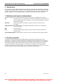
1. Introduction
The Dynamic Timing Control Box (YDT262) is used to determine the timing position of diesel fuel
injection pumps. It is used in conjunction with a host test bench (to mount and drive the fuel pump), a
rotary encoder (providing angular position information), and a piezo pickup (giving the point of
injection signal).
2. Definition of Terms and Abbreviations
The following terms and abbreviations are used in this manual and/or in the YDT262 software.
SP Start Position. The box records a reference point for starting position (effectively
0 degrees). This is used later when calculating the Overcheck Angle.
Offset The angular offset to be applied from the point of injection to the locking position.
Trigger Level The piezo signal trigger level at which the angular position is recorded.
POI Point of Injection
RLP Required Locking Position. This is equal to POI plus/minus the Offset.
Overcheck Angle The difference between SP and RLP.
3. Principle of Operation
The rotary encoder is mounted on the pump drive coupling and the piezo pickup is connected to one
of the pump delivery valves. The piezo pickup provides a signal once every revolution at the point of
injection. By comparing this signal with the angular position information from the rotary encoder, the
point of injection angle is found.
The actual position is found by taking a number of samples at a given speed. The software then
calculates the average position and, once the drive has been stopped, provides you with an angular
countdown so that you can rotate the pump around to that position.
THIS IS AN UNCONTROLLED DOCUMENT downloaded by Lukas Matuska on 16 Feb 2016
Any technical intervention requires certified Hartridge training. Contact Hartridge Ltd for details.

DELPHI DIESEL AFTERMARKET YDT262 Operating and Servicing Manual
HL018, Issue 2 7
4. Operation
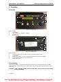
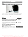
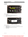
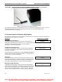
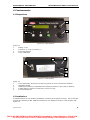
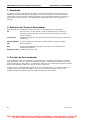
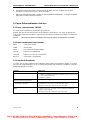
4.1 Layout
Figure 4.1: Top View
Figure 4.1 Key:
1 2*20 display
2 Up (), Down (), and Enter () buttons
3 Piezo socket
4 Encoder socket
Figure 4.2: Bottom View
Figure 4.2 Key:
1 IEC Power inlet socket (accepts a range of standard connector leads).
2 On/Off Switch
3 120V/240V selector for nominal 115V/230V 50/60Hz AC single phase supply.
4 Power input fuse (2A anti-surge, 20mm*5mm)
5 RS232 connection
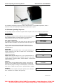
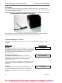
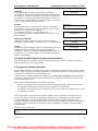
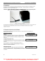
4.2 Installation
The YDT262 requires a standard IEC single-phase power lead, to be purchased locally. An EMC
shielding ferrite is supplied with the kit. Clip the ferrite onto the single-phase power lead as shown in
Figure 4.3.
CAUTION Set the 120V/240V voltage selector switch (Item 3, Figure 4.2) to the correct setting
for the local voltage.
1
2
4
3
5
3
4
1
2
THIS IS AN UNCONTROLLED DOCUMENT downloaded by Lukas Matuska on 16 Feb 2016
Any technical intervention requires certified Hartridge training. Contact Hartridge Ltd for details.

YDT262 Operating and Servicing Manual DELPHI DIESEL AFTERMARKET
8 HL018, Issue 2
Figure 4.3: Clip-on Ferrite
The YDT262 is designed to hang on the rim of the test stand. If using with Pumpmaster, AVM, or
PGM test stands, the additional adapter bracket will also be required.
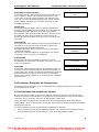
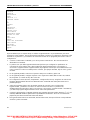
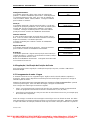
4.3 Software Operating Sequence
The operating sequence for the box together with examples of the screen displays is given below.
Operating Step
Display Example
Power on
The display shows the version number and the last-used language.
Press Up/Down buttons to change language. Press Enter to
confirm and move on; the box records SP at this point.
VERSION 1.0
ENGLISH
Zero Angle Confirmation
The software confirms that the zero angle (SP) has been recorded.
Up/Down buttons disabled. Press Enter to confirm and move on.
If unsuccessful, the message “ZERO ANGLE ERROR” will be
displayed and all buttons will be disabled – refer to Section 5.3
Troubleshooting.
ZERO ANGLE
RECORDED
Offset Value
Display shows last-used offset value. Press Up/Down buttons to
change, scroll from 0.0 to 359.9 in steps of 0.1. Press Enter to
confirm and move on.
OFFSET:
0.0 DEG
Trigger level setting
Display shows last-used trigger level. Press Up/Down buttons to
change – the following levels are available: 25%, 50%, 72%, 75%
of peak voltage, or 100mV, 200mV, 400mV, 800mV. Press Enter to
confirm and move on.
TRIGGER LEVEL:
25%
Variation
Display shows the angle between piezo signals. This gives an
indication of any problems with the input signals (it should read
360 when the pump is running at constant speed). Press Enter
when value is stable and ready to test. Up/down buttons disabled.
VARIATION
359.8 DEG
Sampling
The box takes 100 samples of the piezo position, then calculates
RLP. All buttons are disabled during learning.
SAMPLING…
THIS IS AN UNCONTROLLED DOCUMENT downloaded by Lukas Matuska on 16 Feb 2016
Any technical intervention requires certified Hartridge training. Contact Hartridge Ltd for details.

DELPHI DIESEL AFTERMARKET YDT262 Operating and Servicing Manual
HL018, Issue 2 9
When complete, the display shows:
Press Enter to move on. Up/down buttons disabled.
PLEASE STOP
TEST BENCH
Overcheck Angle
The display shows the Overcheck Angle. Press Enter to move on.
Up/down buttons disabled.
OVERCHECK ANGLE:
2.10 DEG
Setting
The display shows the angle between the current position and RLP
(in direction of rotation). As the drive is rotated (by hand) the angle
displayed counts down to 0.
Up/down buttons disabled. Enter returns to offset screen.
ROTATE TO ZERO:
123.04 DEG
4.4 Setting / Overchecking the Timing Position
For details on setting and overchecking the timing position, refer to Delphi Service Instruction Note
number DT339.
4.5 Downloading an Alternate Language
The YDT262 is supplied pre-loaded with the following languages: English, French, German, Italian,
Spanish, and Portuguese. There is additional space allocated in the memory for one extra language,
which can be downloaded into the YDT262 from a PC.
When there is no additional language loaded the message “USER NOT AVALABLE” will appear when
you scroll through the languages. To escape from this message, press the Enter button.
To download an alternate language you will need the following:
Any PC with a serial communications program, e.g. Terminal or HyperTerminal (these are
standard programs supplied with Windows 3.x, 95, 98, and NT).
A standard 9-way D female to 9-way D female serial cable, e.g. RS Components part no. 215-
410.
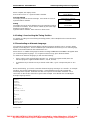
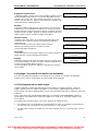
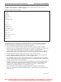
Before downloading, you need to create the alternate language messages as a text file. An example
text file is given below (with English messages). Open Notepad and copy this example file,
translating where required. Note that each line can only have 20 characters maximum. Put 2
semicolons on the last line of the file as given in the example. Save the file and close Notepad.
Example language text file:
ENGLISH
FRENCH
GERMAN
ITALIAN
SPANISH
PORTUGUESE
USER
VERSION 1.2
TRIGGER LEVEL:
%
MV
OFFSET:
DEG
VARIATION
SAMPLING...
PLEASE STOP
TEST BENCH
THIS IS AN UNCONTROLLED DOCUMENT downloaded by Lukas Matuska on 16 Feb 2016
Any technical intervention requires certified Hartridge training. Contact Hartridge Ltd for details.

YDT262 Operating and Servicing Manual DELPHI DIESEL AFTERMARKET
10 HL018, Issue 2
OVERCHECK ANGLE
ROTATE TO ZERO
DEG
SEND TEXT
READY
USER NOT AVAILABLE
ZERO ANGLE
RECORDED
ZERO ANGLE
ERROR
;;
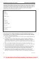
The procedure below refers to HyperTerminal. Other programs will be similar – the important
information is the COM port setup given in steps 4 and 5; refer to the operating instructions for your
particular program to set these.
1. Connect the cable between the YDT262 and one of the PC COM ports. Do not switch on the
YDT262 yet.
2. The first time you use HyperTerminal you will need to configure the communication settings. To
do this, open HyperTerminal (Start > Programs > Accessories > HyperTerminal > HyperTerminal).
It will assume you are making a new connection. Enter a name for the connection, e.g. YDT262,
choose an icon, then press OK.
3. In the next box select the COM port you are using and press OK.
4. In the next box, configure the port as follows, and then press OK. Baud: 9600; Data Bits: 8;
Parity: None; Stop Bits: 1; Flow Control: None.
5. Under ASCII setup (File, Properties, Settings, ASCII Setup), ensure that the “Send line ends with
line feeds” option is selected, then click OK twice to return to the main screen.
6. Choose File, Save. This saves the connection information as a HyperTerminal file, and puts a
link to it on the Start menu. Next time, you can just click on this link (Start > Programs >
Accessories > HyperTerminal > YDT262.ht) and it will open HyperTerminal with the correct
settings.
7. Switch on the YDT262 while holding down the Up and Down buttons. The message “SEND
TEXT” will appear on the display. You are now ready to transfer the language file.
8. In HyperTerminal select Transfer, Send Text File, and then browse to find your language text file
and select Open.
9. When the download is complete, the box will display “READY”. Press Enter to return to normal
operating mode.
THIS IS AN UNCONTROLLED DOCUMENT downloaded by Lukas Matuska on 16 Feb 2016
Any technical intervention requires certified Hartridge training. Contact Hartridge Ltd for details.

DELPHI DIESEL AFTERMARKET YDT262 Operating and Servicing Manual
HL018, Issue 2 11
5. Spares and Service
5.1 YDT262 Spares
The only serviceable parts in the YDT262 are the fuses.
There are two 1A fuses on the PCB itself (marked F1, F2), plus one 2A anti-surge fuse in the single-
phase socket. These are standard 5*20mm fuses that can be purchased locally.
WARNING! DISCONNECT THE ELECTRICAL SUPPLY BEFORE REMOVING THE COVER.
5.2 Related Parts/Tools
AE23 Aux Piezo Cable
26605 Piezo Sensor
AE24 2048ppr Auxiliary Encoder
7044-8 Coupling Extractor
7244-231 Drive Hub Extractor
AA1473 Coupling Spanner
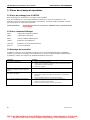
5.3 Troubleshooting
The following table outlines procedures for dealing with simple problems. For anything not covered
here, or if the checks listed do not solve the problem, refer your national Delphi Distributor.
Symptom
Checks
A. YDT262 does not power up
1. Check the electrical supply.
2. Check the 120/240V selector switch is correctly set for the local supply.
3. Check the 3 fuses.
B. YDT262 powers up, but unexpected
messages/characters appear.
1. Switch off, wait a few seconds, then switch back on.
C. Variation screen shows 0 degrees, or is
not stable at 360 degrees.
1. Check the encoder is connected securely.
2. Check the piezo sensor and cable are connected securely.
3. Switch off, wait a few seconds, then switch back on.
D. “ZERO ANGLE ERROR” message
appears.
1. The pump drive shaft must be stationary to record the zero angle. Ensure
the pump is stationary when powering on the unit.
2. Switch off, wait a few seconds, then switch back on.
THIS IS AN UNCONTROLLED DOCUMENT downloaded by Lukas Matuska on 16 Feb 2016
Any technical intervention requires certified Hartridge training. Contact Hartridge Ltd for details.

THIS IS AN UNCONTROLLED DOCUMENT downloaded by Lukas Matuska on 16 Feb 2016
Any technical intervention requires certified Hartridge training. Contact Hartridge Ltd for details.

DELPHI DIESEL AFTERMARKET YDT262 Manuel d’utilisation et d’entretien
HL018, Issue 2 13
FRANCAIS
Avant-propos
Copyright
DT Assembly & Test - Europe Ltd. se réserve les copyrights de toutes les informations et de toutes
les illustrations contenues dans cette publication qui est fournie à titre confidentiel et qui ne doit pas
être utilisée à des fins autres que celles pour laquelle elle a été fournie à l'origine. Cette publication ne
doit pas être reproduite, en entier ou en partie, sans l'autorisation par écrit de cette société.
© DT Assembly & Test - Europe Ltd.
Consignes de sécurité
L'appareil YDT262 est utilisé en conjonction avec un banc d'essai récepteur. Il faut respecter les
règles et les précautions de sécurité élémentaires liées à l'utilisation du banc d'essai récepteur.
Avertissements, mises en garde et remarques
Les consignes de sécurité contenues dans cette publication et désignée par les mots
AVERTISSEMENT, ATTENTION ou REMARQUE donnent des informations sur les dangers
potentiels pour le personnel ou les équipements. Si ces consignes ne sont pas respectées, cela
risque d'entraîner des blessures graves pour le personnel et/ou des dégâts pour le matériel. Ces
consignes se présentent comme suit :
AVERTISSEMENT ! INDIQUE QU'UNE SITUATION RISQUE DE PRÉSENTER UN DANGER
POUR LE PERSONNEL. DES INSTRUCTIONS SONT FOURNIES AFIN
D'ÉVITER TOUT RISQUE DE BLESSURES CORPORELLES.
ATTENTION ! Indique qu'il existe des conditions susceptibles d'entraîner des dégâts
du matériel. Des instructions sont données pour éviter d'endommager le
matériel.
REMARQUE Donne des informations supplémentaires afin d'éclaircir certains points là où il
pourrait y avoir des confusions.
Avertissements généraux
S'assurer que le niveau d'éclairage est suffisant pour obtenir un fonctionnement
sûr et efficace du matériel.
Pendant les essais, il y a des risques d'accidents pour le personnel non autorisé.
Pendant le fonctionnement du matériel, il est impératif que toute personne non
formée soit éloignée de la zone d'essai. Seul le personnel qualifié doit faire
fonctionner ce matériel.
Ce matériel contient des dispositifs sensibles aux décharges électrostatiques.
Respecter les précautions nécessaires pour manipuler des dispositifs sensibles
aux décharges électrostatiques. Ne pas toucher aux circuits imprimés ni aux
connexions et composants électroniques connexes.
THIS IS AN UNCONTROLLED DOCUMENT downloaded by Lukas Matuska on 16 Feb 2016
Any technical intervention requires certified Hartridge training. Contact Hartridge Ltd for details.

YDT262 Manuel d’utilisation et d’entretien DELPHI DIESEL AFTERMARKET
14 HL018, Issue 2
1. Introduction
Le boîtier de commande de temporisation dynamique (YDT262) sert à établir la position de
distribution des pompes à injection de gazole. Il est utilisé en conjonction avec un banc d'essai
récepteur (pour monter et entraîner la pompe à carburant), un codeur rotatif (qui fournit des
informations sur la position angulaire) et un capteur piézoélectrique (qui donne le signal du point
d'injection).
2. Définition des expressions et abréviations
Les expressions et abréviations suivantes sont utilisées dans ce manuel et/ou dans le logiciel
YDT262.
PD Position de départ. Le boîtier enregistre un point de référence comme position
de départ (en fait, 0 degré). Ce point servira ultérieurement à calculer le
surcontrôle.
Offset L'offset angulaire à appliquer entre le point d'injection et la position de
verrouillage.
Seuil de tension Le seuil de tension du signal piézoélectrique où est enregistrée la position
angulaire.
PDI Point d'injection
PVR Position de verrouillage requise. Cette position est égale au point d'injection plus
ou moins l'offset.
Surcontrôle Différence entre la PD (Position de départ) et PVR (Position de verrouillage
requise).
3. Principle de fonctionnement
Le codeur rotatif est monté sur l'accouplement d'entraînement de la pompe et le capteur
piézoélectrique est relié à l'une des soupapes de refoulement de la pompe. Le capteur
piézoélectrique émet un signal une fois par tour, au point d'injection. En comparant ce signal avec les
informations sur la position angulaire transmises par le codeur rotatif, on peut trouver l'angle du point
d'injection.
Pour trouver la position réelle, on prend un certain nombre de relevés à une vitesse donnée. Le
logiciel calcule alors la position moyenne et, après l'arrêt de l'entraînement, il vous donne un débours
angulaire afin de vous permettre de faire tourner la pompe jusqu'à cette position.
THIS IS AN UNCONTROLLED DOCUMENT downloaded by Lukas Matuska on 16 Feb 2016
Any technical intervention requires certified Hartridge training. Contact Hartridge Ltd for details.

DELPHI DIESEL AFTERMARKET YDT262 Manuel d’utilisation et d’entretien
HL018, Issue 2 15
4. Fonctionnement
4.1 Agencement
Figure 4.1 : Vue du dessus
Figure 4.1 Légende :
1. Affichage de 2*20
2. Touches Haut (), Bas () et Entrer ()
3. Prise piézo
4. Prise codeur
Figure 4.2 : Vue du dessous
Figure 4.2 Légende :
1. Prise d'alimentation électrique IEC (accepte toute une gamme de fils de connecteur standards).
2. Commutateur Marche/Arrêt
3. Sélecteur 120 V/240 V pour une alimentation nominale monophasée 115 V/230 V 50/60 Hz c.a.
4. Fusible d'alimentation électrique (2 A contre les surtensions, 20 mm*5 mm)
5. Connexion RS232
4.2 Installation
Pour le YDT262, il faut prévoir un câble électrique monophasé IEC standard que vous pourrez vous
procurer localement. Un atténuateur de blindage à compatibilité électromagnétique en ferrite est
1
2
4
3
5
3
4
1
2
THIS IS AN UNCONTROLLED DOCUMENT downloaded by Lukas Matuska on 16 Feb 2016
Any technical intervention requires certified Hartridge training. Contact Hartridge Ltd for details.

YDT262 Manuel d’utilisation et d’entretien DELPHI DIESEL AFTERMARKET
16 HL018, Issue 2
fourni avec le kit. Encliquetez cet atténuateur sur le câble électrique monophasé comme illustré en
Figure 4.3.
ATTENTION Réglez le commutateur de tension 120 V/240 V (Poste 3, Figure 4.2) au réglage
correct correspondant à la tension du pays.
Figure 4.3 : Ferrite éclipsable
Le YDT262 est conçu pour être suspendu au bord du banc d'essai. Si vous utilisez le Pumpmaster
AVM ou les bancs d'essai PGM, il faudra prévoir en plus un support d'adaptation supplémentaire.
4.3 Séquence d'utilisation du logiciel
Vous trouverez ci-dessous la séquence d'utilisation du boîtier, ainsi que des exemples d'affichage à
l'écran.
Étape d'utilisation
Exemple d'affichage
Mise sous tension
L'écran indique le numéro de la version et la dernière langue utilisée.
Appuyez sur les touches Haut/Bas pour changer de langue.
Appuyez sur Entrer pour confirmer votre choix, puis passez à l'étape
suivante ; le boîtier enregistre la PD.
VERSION 1.0
FRANÇAIS
Confirmation de l'angle zéro
Le logiciel confirme que l'angle zéro (PD) a été enregistré. Touches
Haut/Bas désactivées. Appuyez sur Entrer pour confirmer et passer
à l'étape suivante.
En cas d'échec, le message “ERREUR ANGLE ZERO” s'affiche à
l'écran et toutes les touches sont désactivées. Reportez-vous au
paragraphe 5.3 "Dépistage des anomalies".
ANGLE ZERO
ENREGISTRE
Offset
L'affichage montre la dernière valeur d'offset utilisée. Appuyez sur
les touches Haut/Bas pour changer, défilez de 0.0 à 359.9 par
incréments de 0.1. Appuyez sur Entrer pour confirmer votre choix,
puis passez à l'étape suivante.
OFFSET :
0.0 DEG
THIS IS AN UNCONTROLLED DOCUMENT downloaded by Lukas Matuska on 16 Feb 2016
Any technical intervention requires certified Hartridge training. Contact Hartridge Ltd for details.

DELPHI DIESEL AFTERMARKET YDT262 Manuel d’utilisation et d’entretien
HL018, Issue 2 17
Réglage du seuil de tension
L'affichage montre le dernier niveau du seuil utilisé. Appuyez sur les
touches Haut/Bas pour changer. Les niveaux disponibles sont les
suivants : 25%, 50%, 72%, 75% de tension de pointe, ou 100 mV,
200 mV, 400 mV, 800 mV. Appuyez sur Entrer pour confirmer votre
choix, puis passez à l'étape suivante.
SEUIL DE TENSION :
25%
Variation
L'affichage montre l'angle entre les signaux piézo. Ceci donne une
indication de tous les problèmes éventuels concernant les signaux
d'entrée (lorsque la pompe fonctionne à vitesse constante, la lecture
affichée doit être de 360). Appuyez sur Entrer lorsque la valeur est
stable et prête à l'essai. Touches Haut/Bas désactivées.
VARIATION :
359.8 DEG
Prise des relevés
Le boîtier prend 100 relevés de la position piézo-électrique, puis
calcule la PVR. Toutes les touches sont désactivées pendant
l'apprentissage.
PRISE DES RELEVES…
Une fois terminé, le message suivant s'affiche à l'écran :
Appuyez sur Entrer pour passer à l'étape suivante.
ARRETEZ MOTEUR SVP
Touches Haut/Bas désactivées.
Surcontrôle
L'affichage indique le surcontrôle. Appuyez sur Entrer pour passer à
l'étape suivante. Touches Haut/Bas désactivées.
SURCONTROLE :
2.10 DEG
Réglage
L'affichage indique l'angle entre la position actuelle et la PVR (dans
le sens de la rotation). Lorsque vous faites tourner l'entraînement (à
la main), l'angle affiché diminue jusqu'à 0.
Touches Haut/Bas désactivées. Appuyez sur Entrer pour revenir à
l'écran Offset.
POSITIONNEZ AU ZERO :
123.04 DEG
4.4 Réglage / Surcontrôle de la position de distribution
Pour des renseignements détaillés sur le réglage et le surcontrôle de la position de distribution,
reportez-vous à la Note d'instructions de service Delphi numéro DT339.
4.5 Téléchargement d'une autre langue
L'appareil YDT262 est fourni déjà téléchargé du logiciel dans les langues suivantes : allemand,
anglais, espagnol, français, italien et portugais. Il y a de l'espace supplémentaire prévu dans la
mémoire pour une langue supplémentaire, que vous pourrez télécharger dans le YDT262 à partir d'un
ordinateur.
S'il n'y a pas de langue supplémentaire téléchargée, le message “PAS DISPONIBLE” s'affiche à
l'écran lorsque vous défilez dans la liste des langues. Pour sortir de ce message, appuyez sur la
touche Entrer.
Pour télécharger une autre langue, vous devez disposer du matériel suivant :
Un ordinateur avec un programme de communications en série, ex. Terminal ou HyperTerminal
(ces programmes sont fournis de série avec Windows 3.x, 95, 98 et NT).
Un câble série standard de femelle en D à 9 voies à femelle en D, ex. Composants RS nº de réf.
215-410.
THIS IS AN UNCONTROLLED DOCUMENT downloaded by Lukas Matuska on 16 Feb 2016
Any technical intervention requires certified Hartridge training. Contact Hartridge Ltd for details.

YDT262 Manuel d’utilisation et d’entretien DELPHI DIESEL AFTERMARKET
18 HL018, Issue 2
Avant de télécharger la langue, vous devez créer les messages dans la langue voulue sous forme de
fichier textuel. Un exemple de fichier textuel est illustré ci-dessous (les messages sont en anglais).
Ouvrez Notepad et copiez cet exemple de fichier, puis faites la traduction comme requis. À noter que
chaque ligne ne peut contenir que 20 caractères au maximum. Inscrivez 2 points virgules à la
dernière ligne, comme indiqué dans l'exemple. Sauvegardez ce fichier et fermez Notepad.
Exemple de fichier textuel pour télécharger une langue :
ENGLISH
FRENCH
GERMAN
ITALIAN
SPANISH
PORTUGUESE
USER
VERSION 1.2
TRIGGER LEVEL:
%
MV
OFFSET:
DEG
VARIATION
SAMPLING...
PLEASE STOP
TEST BENCH
OVERCHECK ANGLE
ROTATE TO ZERO
DEG
SEND TEXT
READY
USER NOT AVAILABLE
ZERO ANGLE
RECORDED
ZERO ANGLE
ERROR
;;
La procédure ci-dessous s'applique à HyperTerminal. Les autres programmes adopteront une
procédure similaire ; les informations importantes sont celles du paramétrage du port COM indiqué
aux paragraphes 4 et 5. Pour effectuer ce paramétrage, reportez-vous aux instructions d'utilisation
correspondant à votre programme particulier.
1. Connectez le câble entre l'appareil YDT262 et l'un des ports COM de l'ordinateur. N'allumez pas
encore le YDT262.
2. La première fois que vous utilisez HyperTerminal, vous devrez configurer les réglages de
communication. Pour cela, ouvrez HyperTerminal (Démarrage > Programmes > Accessoires >
HyperTerminal > HyperTerminal). Le système va supposer que vous faites une nouvelle
connexion. Entrez le nom de la connexion, ex. YDT262, choisissez une icône, puis appuyez sur
OK.
3. Dans la case suivante, sélectionnez le port COM que vous utilisez, puis appuyez sur OK.
4. Dans la case suivante, configurez le port comme suit, puis appuyez sur OK. Baud : 9600 ; Bits :
8 ; Parité : Néant ; Bits d'arrêt : 1 ; Contrôle de débit : Néant.
5. Dans le paramétrage ASCII (Fichier, Propriétés, Réglages, Paramétrage ASCII), vérifiez que
l'option “Send line ends with line feeds” (Envoyer fins de ligne avec changement de ligne) est
cochée, puis cliquez à deux reprises sur OK pour revenir à la page d'écran principale.
6. Choisissez File, Save (Fichier, Sauvegarder). Les informations sur la connexion sont alors
sauvegardées sous forme de fichier HyperTerminal, ce qui place un lien sur le menu de
Démarrage. La prochaine fois, il vous suffit de cliquer sur ce lien (Démarrage > Programmes >
THIS IS AN UNCONTROLLED DOCUMENT downloaded by Lukas Matuska on 16 Feb 2016
Any technical intervention requires certified Hartridge training. Contact Hartridge Ltd for details.

DELPHI DIESEL AFTERMARKET YDT262 Manuel d’utilisation et d’entretien
HL018, Issue 2 19
Accessoires > HyperTerminal > YDT262.ht) pour ouvrir HyperTerminal avec les paramétrages
corrects.
7. Allumez le YDT262 tout en maintenant enfoncées les touches Haut et Bas. Le message “SEND
TEXT” s'affiche à l'écran. Vous êtes alors prêt à passer au fichier de langue.
8. Dans HyperTerminal, sélectionnez Transfer, Send Text File, puis naviguez pour trouver votre
fichier textuel de langue, et sélectionnez Open.
9. Une fois le téléchargement terminé, la case affiche “READY”. Appuyez sur Entrer pour revenir au
mode d'utilisation normal.
THIS IS AN UNCONTROLLED DOCUMENT downloaded by Lukas Matuska on 16 Feb 2016
Any technical intervention requires certified Hartridge training. Contact Hartridge Ltd for details.

YDT262 Manuel d’utilisation et d’entretien DELPHI DIESEL AFTERMARKET
20 HL018, Issue 2
5. Pièces de rechange et réparations
5.1 Pièces de rechange pour le YDT262
Dans le YDT262, les seules pièces à changer sont les fusibles.
Il y a deux fusibles de 1 A sur la carte imprimée (marquée F1, F2), plus un fusible de 2 A de
protection contre les surtensions dans la prise monophasée. Il s'agit de fusibles standards 5*20 mm
que vous pourrez vous procurer localement.
AVERTISSEMENT ! AVANT DE RETIRER LE COUVERCLE, DÉBRANCHEZ L'ALIMENTATION
ÉLECTRIQUE.
5.2 Pièces connexes/Outillages
AE23 Câble piézo-électrique auxiliaire
26605 Capteur piézo-électrique
AE24 Codeur auxiliaire 2048 par paire
7044-8 Extracteur d'accouplement
7244-231 Extracteur de moyeu d'entraînement
AA1473 Clé d'accouplement
5.3 Dépistage des anomalies
Le tableau ci-dessous donne quelques procédures qui vous permettront d'éliminer les problèmes
simples. Pour toutes les anomalies non mentionnées ici, ou si les contrôles indiqués n'éliminent pas
le problème, veuillez vous adresser au distributeur Delphi de votre pays.
Symptôme
Contrôles
A. YDT262 ne s'allume pas
1. Vérifiez l'alimentation électrique.
2. Vérifiez que le commutateur 120/240 V est mis sur la tension correcte,
correspondant à celle de votre pays.
3. Vérifiez les 3 fusibles.
B. YDT262 s'allume, mais des
messages/caractères insolites s'affichent à
l'écran.
1. Éteignez, attendez quelques secondes, puis rallumez.
C. La page Variation indique 0 degré ou n'est
pas stable à 360 degrés.
1. Vérifiez que le codeur est fermement branché.
2. Vérifiez que le capteur et le câble piézo-électriques sont fermement
branchés.
3. Éteignez, attendez quelques secondes, puis rallumez.
D. Le message “ERREUR ANGLE ZERO”
s'affiche à l'écran.
1. L'arbre d'entraînement de la pompe doit être immobilisé afin
d'enregistrer l'angle zéro. Lors de la mise sous tension de l'appareil,
vérifiez que la pompe est immobilisée.
2. Éteignez, attendez quelques secondes, puis rallumez.
THIS IS AN UNCONTROLLED DOCUMENT downloaded by Lukas Matuska on 16 Feb 2016
Any technical intervention requires certified Hartridge training. Contact Hartridge Ltd for details.
La pagina sta caricando ...
La pagina sta caricando ...
La pagina sta caricando ...
La pagina sta caricando ...
La pagina sta caricando ...
La pagina sta caricando ...
La pagina sta caricando ...
La pagina sta caricando ...
La pagina sta caricando ...
La pagina sta caricando ...
La pagina sta caricando ...
La pagina sta caricando ...
La pagina sta caricando ...
La pagina sta caricando ...
La pagina sta caricando ...
La pagina sta caricando ...
La pagina sta caricando ...
La pagina sta caricando ...
La pagina sta caricando ...
La pagina sta caricando ...
La pagina sta caricando ...
La pagina sta caricando ...
La pagina sta caricando ...
La pagina sta caricando ...
La pagina sta caricando ...
La pagina sta caricando ...
La pagina sta caricando ...
La pagina sta caricando ...
La pagina sta caricando ...
La pagina sta caricando ...
La pagina sta caricando ...
La pagina sta caricando ...
La pagina sta caricando ...
La pagina sta caricando ...
-
 1
1
-
 2
2
-
 3
3
-
 4
4
-
 5
5
-
 6
6
-
 7
7
-
 8
8
-
 9
9
-
 10
10
-
 11
11
-
 12
12
-
 13
13
-
 14
14
-
 15
15
-
 16
16
-
 17
17
-
 18
18
-
 19
19
-
 20
20
-
 21
21
-
 22
22
-
 23
23
-
 24
24
-
 25
25
-
 26
26
-
 27
27
-
 28
28
-
 29
29
-
 30
30
-
 31
31
-
 32
32
-
 33
33
-
 34
34
-
 35
35
-
 36
36
-
 37
37
-
 38
38
-
 39
39
-
 40
40
-
 41
41
-
 42
42
-
 43
43
-
 44
44
-
 45
45
-
 46
46
-
 47
47
-
 48
48
-
 49
49
-
 50
50
-
 51
51
-
 52
52
-
 53
53
-
 54
54


Delphi YDT262 Operating And Servicing Manual
- Tipo
- Operating And Servicing Manual
in altre lingue
- English: Delphi YDT262
- français: Delphi YDT262
- español: Delphi YDT262
- Deutsch: Delphi YDT262
- português: Delphi YDT262
Documenti correlati

Altri documenti
-
Regal 42 Fly-Grande Coupe Manuale del proprietario
-
Volvo Penta IPS 600 Manuale utente
-
Maestro 100 3G Quick Start Manual & User Manual
-
Haba 4638 Manuale del proprietario
-
MV Agusta Brutale 675 Manuale utente
-
-
-
 Netgate SG-3100 Manuale utente
-
 AGUSTA BRUTALE 800 Manuale utente
-

