Netgate SG-3100 Manuale utente
- Categoria
- Gateway / controllori
- Tipo
- Manuale utente

Security Gateway Manual
SG-3100
Netgate
Feb 19, 2019

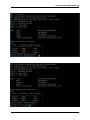
CONTENTS
1 I/O Ports 2
2 SG-3100 Switch Overview 5
3 Getting Started 11
4 Connecting to Console Port 22
5 Additional Resources 29
6 Warranty and Support Information 30
7 Safety and Legal 31
8 Reinstalling pfSense 39
9 Optional M.2 SATA Installation 42
i

Security Gateway ManualSG-3100
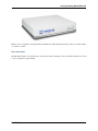
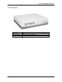
Thank you for your purchase of the pfSense® SG-3100 System. This hardware platform provides a powerful, reliable,
cost-effective solution.
Quick Start Guide
The Quick Start Guide covers the first time connection procedures and will provide you with the information you need
to get your appliance up and running.
CONTENTS 1

CHAPTER
ONE
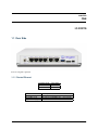
I/O PORTS
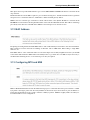
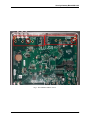
1.1 Rear Side
Ports are assigned as pictured.
1.1.1 Routed Ethernet
Interface Name Port Name
WAN mvneta2
OPT1 mvneta0
LED Pattern Description
Left LED only green Flashes with 1Gb traffic, solid with link.
Both LEDs green Both flash with 100Mb traffic, solid with link.
Right LED only green Flashes with 10Mb traffic, solid with link.
2

Security Gateway ManualSG-3100
1.1.2 Switched Ethernet
Interface Name Port Name
LAN1 mvneta1
LAN2 mvneta1
LAN3 mvneta1
LAN4 mvneta1
LED Pattern Description
Both LEDs green Left Flashes with 1Gb traffic, solid with link.
Left LED only green Left flashes with 100Mb traffic, solid with link.
Right LED only green Left Flashes with 10Mb traffic, solid with link.
Note: Prior to pfSense software version 2.4.3, the switched Ethernet ports on the SG-3100 did not support auto
MDI-X and required crossover cable unless the client-side connection supported auto MDI-X. This was resolved with
2.4.3 and later versions and a crossover cable is no longer required.
Warning: The LAN ports do not support the Spanning Tree Protocol (STP). Two or more ports connected to
another Layer 2 switch, or connected to 2 or more different interconnected switches, could create a flooding loop
between the switches. This can cause the router to stop functioning until the loop is resolved.
1.1.3 Other Ports
• Power (12 VDC with threaded locking connector)
• Recessed Reset Button (performs a hard reset, immediately turning the system off)
• USB 3.0
• Micro SIM
• Console (Mini-USB)
Warning: A hard reset of the system could cause data corruption and should be avoided. Halt or reboot the
system through the console menu or the web configurator to avoid data corruption.
1.1. Rear Side 3

Security Gateway ManualSG-3100
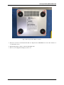
1.2 Front Side
LED Pattern Description
Boot Process The sequence, circle -> square -> diamond, quickly flashes blue.
Boot Completed The diamond slowly flashes blue.
Update is Available The square slowly flashes orange.
1.2. Front Side 4

CHAPTER
TWO
SG-3100 SWITCH OVERVIEW
This optional guide shows the steps required to configure the 4 switched Ethernet ports as discrete ports.
Note: When connecting to the webConfigurator, be sure you are NOT connected to the port you are going to configure
or you will lose connectivity during this procedure.
The following attributes are used in this configuration guide but can be changed to suit your particular requirements:
SG-3100 Ethernet Port: LAN4
IP Address Assignment: 192.168.100.1/24
VLAN Tag: 4084 (VLAN tags should be 4081-4084 for LAN Ports 1-4)
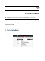
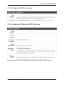
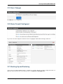
2.1 Configuring the Switch
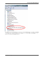
1. Open the pfSense WebGUI and log in.
2. From the menu, navigate to Interfaces > Assignments.
3. Go to the VLANs sub-menu.
5

Security Gateway ManualSG-3100
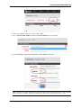
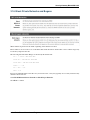
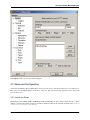
4. In the lower right-hand corner of the screen, click + Add.
5. Choose mvneta1 (MAC Address) - lan from the Parent Interface drop-down menu.
6. Set the VLAN Tag to 4084. Type Lan port 4 as the Description. Click Save.
Note: 4084 in is used as an example in this guide. The value for the tags must be unique for each VLAN and
must be between 1 and 4094. Avoid using values that are already in use. Best practice is not to use 1.
2.1. Configuring the Switch 6

Security Gateway ManualSG-3100
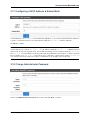
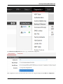
7. Go to the Interface Assignments sub-menu.
8. Ensure Available network ports: is correct. It is VLAN 4084 on mvneta1 - lan (Lan port 4) in this example.
Click on + Add.
9. Click on OPT2. This is the Interface that matches the new VLAN being created.
10. Check the Enable Interface check-box.
11. Change the IPv4 Configuration Type from None to Static IPv4.
2.1. Configuring the Switch 7

Security Gateway ManualSG-3100
12. Scroll down and make the IPv4 Address 192.168.100.1/24 (in this example).
13. Click Save.
14. Click Apply Changes.
15. Go to Interfaces -> Switches.
16. Go to the VLANs sub-menu. Click in the Enable 802.1q VLAN mode check-box and click Save.
17. You will notice that the table changes. Click + Add Tag.
2.1. Configuring the Switch 8

Security Gateway ManualSG-3100
18. Type 4084 for the VLAN Tag and 4 for Member(s). This represents LAN4 (port 4) and tagged should be
unchecked.
19. Click + Add Member to add the LAN Uplink, 5. This member should be tagged as shown.
20. Click Save.
21. Click on |fa-pencil| beside VLAN group 0.
2.1. Configuring the Switch 9

Security Gateway ManualSG-3100
22. Click Delete beside Member(s) 4. This will remove LAN4 from this VLAN group.
23. Click Save.
24. Go to the Ports sub-menu.
25. Click on Port VID 1 beside LAN4. Backspace through 1 and insert 4084, the new VLAN ID.
26. Click Save.
This completes the configuration of a discrete port on the SG-3100.
You will need to create the appropriate firewall rules because by default, all traffic is blocked. Go to Firewall > Rules
and then the OPT2 sub-menu (in this example) to configure the firewall rules.
You should also enable DHCP if necessary, by going to Services > DHCP Server > OPT2 (for the example above).
2.1. Configuring the Switch 10

CHAPTER
THREE
GETTING STARTED
The basic firewall configuration begins with connecting the pfSense appliance to the Internet. Neither the modem nor
the pfSense appliance should be powered on at this time.
Establishing a connection to an Internet Service Provider (ISP) starts with connecting one end of an Ethernet cable to
the WAN port (shown in the I/O Ports section) of the pfSense appliance.
Warning: The default LAN subnet on the firewall is 192.168.1.0/24. The same subnet cannot be used on
both WAN and LAN, so if the subnet on the WAN side of the firewall is also 192.168.1.0/24, disconnect the
WAN interface until the LAN interface has been renumbered to a different subnet.
The opposite end of the same Ethernet cable should be inserted in to the LAN port of the ISP-supplied modem. The
modem provided by the ISP might have multiple LAN ports. If so, they are usually numbered. For the purpose of this
installation, please select port 1.
The next step is to connect the LAN port (shown in the I/O Ports section) of the pfSense appliance to the computer
which will be used to access the firewall console.
Connect one end of the second Ethernet cable to the LAN port (shown in the I/O Ports section) of the pfSense appli-
ance. Connect the other end to the network connection on the computer. In order to access the web configurator, the
PC network interface must be set to use DHCP, or have a static IP set in the 192.168.1.x subnet with a subnet
mask of 255.255.255.0. Do not use 192.168.1.1, as this is the address of the firewall, and will cause an IP
conflict.
3.1 Initial Setup
The next step is to power up the modem and the firewall. Plug in the power supply to the power port (shown in the I/O
Ports section).
Once the modem and pfSense appliance are powered up, the next step is to power up the computer.
Once the pfSense appliance is booted, the attached computer should receive a 192.168.1.x IP address via DHCP
from the pfSense appliance.
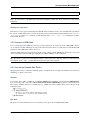
3.2 Logging Into the Web Interface
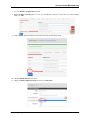
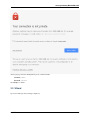
Browse to https://192.168.1.1 to access the web interface. In some instances, the browser may respond with a message
indicating a problem with website security. Below is a typical example in Google Chrome. If this message or similar
message is encountered, it is safe to proceed.
11

Security Gateway ManualSG-3100
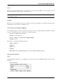
At the login page enter the default pfSense password and username:
Username admin
Password pfsense
Click Login to continue
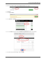
3.3 Wizard
Upon successful login, the following is displayed.
3.3. Wizard 12

Security Gateway ManualSG-3100
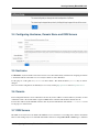
3.4 Configuring Hostname, Domain Name and DNS Servers
3.5 Hostname
For Hostname, any desired name can be entered as it does not affect functionality of the firewall. Assigning a hostname
to the firewall will allow the GUI to be accessed by hostname as well as IP address.
For the purposes of this guide, use pfsense for the hostname. The default hostname, pfsense may be left un-
changed.
Once saved in the configuration, the GUI may be accessed by entering http://pfsense as well as http://192.168.1.1
3.6 Domain
If an existing DNS domain is in use within the local network (such as a Microsoft Active Directory domain), use that
domain here. This is the domain suffix assigned to DHCP clients, which should match the internal network.
For networks without any internal DNS domains, enter any desired domain name. The default localdomain is used
for the purposes of this tutorial.
3.7 DNS Servers
The DNS server fields can be left blank if the DNS Resolver is used in non- forwarding mode, which is the default
behavior. The settings may also be left blank if the WAN connection is using DHCP, PPTP or PPPoE types of Internet
3.4. Configuring Hostname, Domain Name and DNS Servers 13

Security Gateway ManualSG-3100
connections and the ISP automatically assigns DNS server IP addresses. When using a static IP on WAN, DNS server
IP addresses must be entered here for name resolution to function if the default DNS Resolver settings are not used.
DNS servers can be specified here even if they differ from the servers assigned by the ISP. Either enter the IP addresses
provided by the ISP, or consider using Google public DNS servers (8.8.8.8, 8.8.4.4). Google DNS servers are
used for the purpose of this tutorial. Click Next after filling in the fields as appropriate.
3.8 Time Server Configuration
3.9 Time Server Synchronization
Setting time server synchronization is quite simple. We recommend using the default pfSense time server address,
which will randomly select an NTP server from a pool.
3.10 Setting Time Zone
Select an appropriate time zone for the location of the firewall. For purposes of this manual, the Timezone setting will
be set to America/Chicago for US Central time.
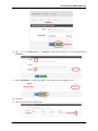
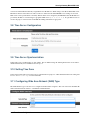
3.11 Configuring Wide Area Network (WAN) Type
The WAN interface type is the next to be configured. The IP address assigned to this section becomes the Public IP
address that this network will use to communicate with the Internet.
3.8. Time Server Configuration 14

Security Gateway ManualSG-3100
This depicts the four possible WAN interface types. Static, DHCP, PPPoE and PPTP. One must be selected from the
drop-down list.
Further information from the ISP is required to proceed when selecting Static, PPPoE and PPTP such as login name
and password or as with static addresses, an IP address, subnet mask and gateway address.
DHCP is the most common type of interface for home cable modems. One dynamic IP address is issued from the
ISP DHCP server and will become the public IP address of the network behind this firewall. This address will change
periodically at the discretion of the ISP. Select DHCP as shown and proceed to the next section.
3.12 MAC Address
If replacing an existing firewall, the WAN MAC address of the old firewall may be entered here, if it can be determined.
This can help avoid issues involved in switching out firewalls, such as ARP caches, ISPs locking to single MAC
addresses, etc.
If the MAC address of the old firewall cannot be located, the impact is most likely insignificant. Power cycle the ISP
router and modem and the new MAC address will usually be able to get online. For some ISPs, it may be necessary to
call them when switching devices, or an activation process may be required.
3.13 Configuring MTU and MSS
MTU or Maximum Transmission Unit determines the largest protocol data unit that can be passed onwards. A 1500-
byte packet is the largest packet size allowed by Ethernet at the network layer and for the most part, the Internet so
leaving this field blank allows the system to default to 1500-byte packets. PPPoE is slightly smaller at 1492-bytes.
Leave this blank for a basic configuration.
3.12. MAC Address 15

Security Gateway ManualSG-3100
3.14 Configuring DHCP Hostname
Some ISPs specifically require a DHCP Hostname entry. Unless the ISP requires the setting, leave it blank.
3.15 Configuring PPPoE and PPTP Interfaces
Information added in these sections is assigned by the ISP. Configure these settings as directed by the ISP
3.14. Configuring DHCP Hostname 16

Security Gateway ManualSG-3100
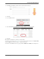
3.16 Block Private Networks and Bogons
When enabled, all private network traffic originating on the internet is blocked.
Private addresses are reserved for use on internal LANs and blocked from outside traffic so these address ranges may
be reused by all private networks.
The following inbound address Ranges are blocked by this firewall rule:
• 10.0.0.1 to 10.255.255.255
• 172.16.0.1 to 172.31.255.254
• 192.168.0.1 to 192.168.255.254
• 127.0.0.0/8
• 100.64.0.0/10
• fc00::/7
Bogons are public IP addresses that have not yet been allocated, so they may typically also be safely blocked as they
should not be in active use.
Check Block RFC1918 Private Networks and Block Bogon Networks.
Click Next to continue.
3.16. Block Private Networks and Bogons 17

Security Gateway ManualSG-3100
3.17 Configuring LAN IP Address & Subnet Mask
A static IP address of 192.168.1.1 and a subnet mask (CIDR) of 24 was chosen for this installation. If there are
no plans to connect this network to any other network via VPN, the 192.168.1.x default is sufficient.
Click Next to continue.
Note: If a Virtual Private Network (VPN) is configured to remote locations, choose a private IP address range more
obscure than the very common 192.168.1.0/24. IP addresses within the 172.16.0.0/12 RFC1918 private
address block are the least frequently used. We recommend selecting a block of addresses between 172.16.x.x
and 172.31.x.x for least likelihood of having VPN connectivity difficulties. An example of a conflict would be If
the local LAN is set to 192.168.1.x and a remote user is connected to a wireless hotspot using 192.168.1.x
(very common), the remote client won’t be able to communicate across the VPN to the local network.
3.18 Change Administrator Password
Select a new Administrator Password and enter it twice, then click Next to continue.
3.17. Configuring LAN IP Address & Subnet Mask 18
La pagina si sta caricando...
La pagina si sta caricando...
La pagina si sta caricando...
La pagina si sta caricando...
La pagina si sta caricando...
La pagina si sta caricando...
La pagina si sta caricando...
La pagina si sta caricando...
La pagina si sta caricando...
La pagina si sta caricando...
La pagina si sta caricando...
La pagina si sta caricando...
La pagina si sta caricando...
La pagina si sta caricando...
La pagina si sta caricando...
La pagina si sta caricando...
La pagina si sta caricando...
La pagina si sta caricando...
La pagina si sta caricando...
La pagina si sta caricando...
La pagina si sta caricando...
La pagina si sta caricando...
La pagina si sta caricando...
La pagina si sta caricando...
La pagina si sta caricando...
La pagina si sta caricando...
La pagina si sta caricando...
La pagina si sta caricando...
-
 1
1
-
 2
2
-
 3
3
-
 4
4
-
 5
5
-
 6
6
-
 7
7
-
 8
8
-
 9
9
-
 10
10
-
 11
11
-
 12
12
-
 13
13
-
 14
14
-
 15
15
-
 16
16
-
 17
17
-
 18
18
-
 19
19
-
 20
20
-
 21
21
-
 22
22
-
 23
23
-
 24
24
-
 25
25
-
 26
26
-
 27
27
-
 28
28
-
 29
29
-
 30
30
-
 31
31
-
 32
32
-
 33
33
-
 34
34
-
 35
35
-
 36
36
-
 37
37
-
 38
38
-
 39
39
-
 40
40
-
 41
41
-
 42
42
-
 43
43
-
 44
44
-
 45
45
-
 46
46
-
 47
47
-
 48
48


Netgate SG-3100 Manuale utente
- Categoria
- Gateway / controllori
- Tipo
- Manuale utente
in altre lingue
- English: Netgate SG-3100 User manual
Altri documenti
-
ZyXEL PMG5318-B20B Manuale utente
-
Planet Technology WBS-200N Manuale utente
-
Allnet ALL02850N Manuale del proprietario
-
Asus TV Box Manuale utente
-
ZyXEL NBG6815 Manuale del proprietario
-
-
-
Ubiquiti AirRouterHP Manuale utente
-
Dlink DVA-2800 Manuale utente
-
Alcatel-Lucent Extended Communication Server Installation & Configuration Manual