La pagina si sta caricando...

OPERATOR’S MANUAL
D12

CALIFORNIA
Proposition 65 Warning
Diesel engine exhaust and some of its constituents are known
to the State of California to cause cancer, birth defects, and
other reproductive harm.
This operator’s manual is also available in the following languages:
Diese Betriebsanleitung ist auch auf
Deutsch erhältlich.
Ein Bestellcoupon ist am Ende der Be-
triebsanleitung zu finden.
Ce manuel d’instructions peut être
commandé en français.
Vous trouverez un bon de commande à la fin
du manuel d’instructions.
Este libro de instrucciones puede soli-
citarse en español.
El cupón de pedido se encuentra al final del
libro.
Den här instruktionsboken kan bestäl-
las på svenska.
Beställningskupong finns i slutet av instrukti-
onsboken.
Questo manuale d’istruzioni può esse-
re ordinato in lingua italiana.
Il tagliando per l’ordinazione è riportato alla
fine del manuale.
Dit instructieboek kan worden besteld
in het Nederlands.
De bestelcoupon vindt u achter in het instruc-
tieboek
Denne instruktionsbog kan bestilles
på dansk.
Bestillingskupon findes i slutningen af instruk-
tionsbogen.
Tämän ohjekirjan voi tilata myös suo-
menkielisenä.
Tilauskuponki on ohjekirjan lopussa.
Este manual de instruções pode ser
encomendado em português.
O talão de requerimento encontra-se no fim
do manual.
Áõôü ôï åã÷åéñßäéï ÷ñÞóçò
äéáôßèåôáé óôçí áããëéêÞ ãëþóóá.
Ãéá íá ðáñáããåßëåôå Ýíá áíôßôõðï,
óõìðëçñþóôå ôç öüñìá ðïõ âñßóêåôáé óôï
ôÝëïò áõôïý ôïõ åã÷åéñéäßïõ ÷ñÞóçò.
Данное руководство оператора
имеется на русском языках.
Для получения инструкции на нужном
языке заполните форму в конце
инструкции.
Bu kullanýcý el kitabý Türkçe diller-
inde mevcuttur.
Birnüshasýný sipariþ etmek için kullanýcý el
kitabýnýn sonundaki formu doldurun.

Welcome aboard
Volvo Penta marine engines are used all over the world. They are used in all possible operating
conditions for professional as well as leisure purposes. That’s not surprising.
After 100 years as an engine manufacturer the Volvo Penta name has become a symbol of reli-
ability, technical innovation, top of the range performance and long service life. We also believe
that this is what you demand and expect of your Volvo Penta engine.
We would like you to read this operator’s manual thoroughly and consider the advice we give on
operation and maintenance before your maiden voyage so that you will be ensured of fulfilling
your expectations. Please pay attention to the safety instructions contained in the manual.
As owner of a Volvo Penta marine engine, we would also like to welcome you to a worldwide
network of dealers and service workshops to assist you with technical advice, service require-
ments and replacement parts. Please contact your nearest authorized Volvo Penta dealer for
assistance.
We also invite you to visit our home page on the Internet at www.volvopenta.com
With warm regards
AB VOLVO PENTA

2
© 2006 AB VOLVO PENTA
We reserve the right to make modifications without prior notice. Printed on environmentally compatible paper.
(Cover: Department of transport (shipping), license 9809095)
Contents
Stopping the engine ........................................... 50
Stop ..................................................................... 50
Cold weather precautions .................................... 51
Laying up ............................................................. 51
Maintenance schedule ....................................... 52
Maintenance ........................................................ 54
Engine, general ................................................... 54
Lubrication system .............................................. 57
Freshwater system .............................................. 61
Seawater system ................................................. 66
Fuel system ......................................................... 70
Electrical system ................................................. 76
Reverse gear ....................................................... 81
Accessoties ......................................................... 83
Laying up/Launching ......................................... 84
Inhibiting .............................................................. 84
Bringing out of storage ........................................ 85
In case of emergency ......................................... 86
Starting with auxiliary batteries ........................... 86
Emergency shifting .............................................. 87
Fault-tracing ......................................................... 88
Diagnostic function .............................................. 89
Fault register ....................................................... 92
Technical data ..................................................... 100
Engine ................................................................. 100
Reverse gear ....................................................... 102
Safety information .............................................. 3
General information ............................................ 3
Boat trips ............................................................. 4
Care and maintenance ........................................ 6
Introduction ......................................................... 8
Running in ........................................................... 8
Fuel and oils ........................................................ 8
Certified engines ................................................. 9
Warranty information ........................................... 9
Identification number .......................................... 10
Presentation ........................................................ 11
Technical description ........................................... 11
Orientation ........................................................... 12
Instruments ......................................................... 13
Instruments .......................................................... 13
Ignition lock .......................................................... 13
Start/stop panel ................................................... 13
Alarm display (optional extra) .............................. 14
EVC control panel................................................ 17
EVC system tachometer ...................................... 18
EVC system display (optional extra) .................... 27
Controls ............................................................... 35
Single lever control .............................................. 35
Two lever control .................................................. 37
Starting the engine ............................................. 38
Before starting ..................................................... 38
General information about starting ...................... 38
Starting method ................................................... 39
Operation ............................................................. 41
Reading instruments ........................................... 41
Alarm ................................................................... 42
Cruising speed .................................................... 42
Synchronising engine speed ............................... 43
Changing the helm station ................................... 43
Operation ............................................................. 45
Low speed ........................................................... 46
Trolling ................................................................. 47
Propeller shaft brake ........................................... 48
Extra equipment .................................................. 49

3
Safety information
Read this chapter very carefully. It has to do with your safety. This describes how safety information is presented
in the instruction book and on the product. It also gives you an introduction to the basic safety rules for using and
looking after the engine.
Check that you heave received the correct instruction book before you read on. If not, please contact
your Volvo Penta dealer.
Incorrect operation can lead to personal injury and damage to products or property. So
read the instruction book through very carefully before you start the engine or do any
maintenance or service work. If there is still something which is unclear or if you feel un-
sure about it, please contact your Volvo Penta dealer for assistance.
This symbol is used in the instruction book and on the product, to call your attention to the
fact that this is safety information. Always read such information very carefully.
Safety texts in the instruction book have the following order of priority:
WARNING! Warns for the risk of personal injury, major damage to product or property, or
serious malfunctions if the instruction is ignored.
IMPORTANT! Is used to call attention to things which could cause damage or malfunctions
to product or property.
NOTE! Is used to call attention to important information, to facilitate work processes or operation.
This symbol is used on our products in some cases and refers to important information in
the instruction book. Make sure that warning and information symbols on the engine are
clearly visible and legible. Replace symbols which have been damaged or painted over.

4
Safety information
Safety advice for boat operation
Your new boat
Read the instruction books and other information
carefully, which came with your new boat. Learn to
handle the engine, controls and other equipment in a
safe and correct manner.
If this is your first boat, or a type of boat you are not
experienced in using, we recommend that you practi-
ce operating the boat in peace and quiet. Get to know
the way the boat reacts to sea and to the controls
under different speed, sea and loading conditions be-
fore you cast off for your first “real” maiden voyage.
Remember that the captain of every boat is required
by law to know and to observe applicable rules for
traffic and safety at sea. Get to know the rules which
apply to you and your waters, by contacting the rele-
vant authority or sea safety organisation.
It is a good idea to go on some kind of boat operation
course. We recommend that you contact a regional
boat or sea safety organisation to find a suitable course.
Accidents and near misses
Life saving statistics show that inadequate care of
boats and engines, and deficiencies in safety equip-
ment are frequent causes of accidents and near misses
at sea.
Make sure that your boat and engine are maintained
in accordance with the advice in each instruction
book, and that the necessary safety equipment is on
board, and is in working condition.
Daily checks
Make it a habit to give the engine and engine bay
a visual check before driving (before starting the
engine) and after operation (when you have stop-
ped the engine). This helps you to quickly discover
whether any leakage of fuel, coolant, oil or any other
abnormal event has happened, or is about to happen.
Manoeuvring
Avoid sudden or surprising rudder movements and
gear shifting. There is a risk that passengers could
fall over, or overboard.
A rotating propeller can cause severe injury. Check
that there is nobody in the water before you engage
forward / astern (reverse) drive. Never drive close to
bathers or in areas where you could reasonably ex-
pect that people could be in the water.
Fuel filling
There is always a risk of fire and explosion during
fuel filling. Smoking is not permissible, and the engi-
ne should be stopped.
Never over-fill the tank.
Shut the tank cap securely. Only use the fuel recom-
mended in the instruction book. The wrong grade of
fuel can cause malfunctions or stop the engine. In a
diesel engine, it can also cause the regulation rod to
bind and the engine will over-rev, entailing a strong
risk of personal injury and machinery damage.
Do not start the engine.
Do not start the engine if you suspect a fuel or LPG
leak in the boat, close to explosive media, or if there
is a spillage of explosive media. An explosive envi-
ronment entails a risk of fire and/or explosion.

5
Safety information
Carbon monoxide poisoning
When a boat moves forwards, an area of low pres-
sure air forms behind the boat. In adverse conditions,
this low pressure can be so strong that the boat’s
own exhaust fumes are sucked into the cockpit or
cabin, which entails a risk of carbon monoxide poiso-
ning for all aboard.
The problem of low-pressure suction is worst in high,
wide boats with a square transom. But even in other
types of boats, low-pressure suction can be a pro-
blem in some conditions, such as if you drive with the
hood up. Other factors which increase the low-pres-
sure effect are wind conditions, load distribution, pit-
ching, trimming, open windows and ventilators etc.
Most modern boats are designed so that the problem
of low-pressure suction is very rare, however. If low-
pressure suction does occur anyway, do not open
hatches or ventilators in the forward part of the boat.
Strangely enough, this makes the problem worse. Try
changing speed, trimming or load distribution instead.
Also try taking down/opening the hood or modifying
it in some other manner. Ask your boat dealer for ad-
vice about the best solution for your particular boat.
Remember
● Safety equipment: Life jackets for everybody aboard, communication equipment, emergency
rockets, approved fire extinguisher, first aid kit, life buoy, anchor, paddle, torches etc.
● Spare parts and tools: Impeller, fuel filters, fuses, tape, hose clamps, engine oil, propeller and
tools for the jobs you could be expected to have to do.
● Take your chart out and study your planned route. Calculate distance and fuel consumption.
Listen to weather reports.
● Tell your friends/relatives about route plans if you undertake a long journey. Remember to notify
changed plans or delays.
● Inform everybody aboard about where the safety equipment is located, and how it works. Make
sure that there is more than one person aboard who can start and operate the boat safely.
This list can be extended, since the need for safety equipment varies with the type of boat, and
where or how it is used etc. We recommend that you ask a regional boat or sea safety organisation
for more detailed maritime safety information.

6
Safety information
Safety advice for care and maintenance work
Preparations
Knowledge
The Instruction Book contains instructions for doing
the most common service and maintenance tasks in
a safe and correct manner. Read them carefully be-
fore starting work.
Literature for more major tasks is available from your
Volvo Penta dealer.
Never do a job if you are not entirely sure about how to
do it. Contact a Volvo Penta dealer for assistance ins-
tead.
Stop the engine.
Stop the engine before opening or removing the engine
hatch/hood. Care and maintenance work should be
done with the engine stopped unless otherwise speci-
fied.
Prevent the engine from being started by cutting the
current with the battery isolator, or remove the cable
from the battery positive pole before you start service
work. Fix a notice by the helmsman’s seat to say that
work is in progress.
Working with, or going close to a running engine
is a safety risk. Loose clothes, long hair, fingers or
dropped tools can catch on rotating components and
cause severe injury. Volvo Penta recommends that all
service work which requires the engine to be running
should be done by a Volvo Penta authorised work-
shop.
Lifting the engine
The existing lugs on the engine (or reverse gear)
should be used for lifting. Always check that the lifting
devices are in good condition and that they have the
correct capacity for the lift (engine weight together
with reverse gear and auxiliaries, if fitted). The engine
should be lifted with an adjustable lifting boom for
safe handling. All chains or cables should be parallel
to each other and should be as square as possible
to the top of the engine. Please note that auxiliary
equipment installed on the engine could change its
centre of gravity. Special lifting devices may then
be needed to obtain the correct balance and safe
handling. Never do any work on an engine which just
hangs from a lifting device.
Before starting
Re-install all guards which have been removed
during service work, before re-starting the engine.
Make sure that there are no tools or other objects left
behind on the engine.
Never start a turbocharged engine without the air
filter in place. The rotating compressor turbine in the
turbocharger can cause severe injury. There is also a
risk that foreign bodies could be sucked in and cause
machinery damage.
Fire and explosion
Fuel and lubrication oil
All fuel, most lubricants and many chemicals are
flammable. Always read and observe the advice on
the packages.
Work on the fuel system must be done with the eng-
ine cold. Fuel leakage and spills on hot surfaces or
electrical components can cause fires.
Store oil and fuel soaked rags and other flammable
material in a fire-proof manner. Oil soaked rags can
self-ignite in certain circumstances.
Never smoke when filling fuel, lubrication oil or close
to fuel filling stations or the engine bay.
Non-original spare parts
Components in fuel systems and electrical systems
on Volvo Penta engines are designed and manufactu-
red to minimise the risk of explosions and fire, in ac-
cordance with applicable legal requirements.
The use of non-original spare parts can cause a fire.
Batteries
Batteries contain and give off an explosive gas, espe-
cially when charged. This gas is very flammable and
highly explosive.
Smoking, open flames or sparks must never occur in
or near to batteries or the battery locker.
Incorrect connection of a battery cable or start cable
can cause a spark which can be sufficient, in its turn,
to make the battery explode.
Start spray
Never use start spray or similar products as a star-
ting aid. Explosions could occur in the inlet manifold.
Danger of personal injury.

7
Safety information
Hot surfaces and fluids
A hot engine always offers the risk of burns. Be on
your guard against hot surfaces, such as the ex-
haust manifold, turbocharger, sump, charge air pipe,
starting heater, hot coolant and hot lubricating oil in
pipes and hoses.
Carbon monoxide poisoning
Only start the engine in a well-ventilated area. When
operated in a confined space, exhaust fumes and
crankcase gases must be ventilated.
Chemicals
Most chemicals, such as glycol, rust preventer, con-
servation oils, degreasers etc. are hazardous. Always
read and observe the advice on the packages.
Some chemicals, such as conservation oils, are flam-
mable and also hazardous to breathe. Ensure good
ventilation and use a protective mask for spraying. Al-
ways read and observe the advice on the packages.
Store chemicals and other hazardous material out of
the reach of children. Hand in surplus or used chemi-
cals to a recycling station for destruction.
Cooling system
There is always a risk of water entry when any work
is done on the seawater system. For this reason,
stop the engine and close the sea cocks before you start
work.
Avoid opening the coolant filling cap when the engine
is hot. Steam or hot coolant can spray out and cause
scalding.
If the filler cap, coolant hose etc., still has to be ope-
ned or removed when the engine is hot, undo the
filler cap slowly and carefully, to let the pressure out
before removing the filler cap completely and starting
work. Note that the coolant can still be hot and cause
scalding.
Lubrication system
Hot oil can cause burns. Avoid skin contact with hot
oil. Make sure that the oil system is de-pressurised
before starting work. Never start or run the engine with
the oil filler cap removed, because of the risk of oil spil-
lage.
Fuel system
Always protect your hands when searching for leaks.
Fluids which leak under pressure can force their way
into body tissue and cause severe injury. Risk of
blood poisoning (septicaemia).
Always cover the alternator if it is located beneath the
fuel filters. Fuel spillage can damage the alternator.
Electrical system
Cut the current
Before any work is done on the electrical system,
the engine must be stopped and the current cut by
switching off the battery isolator. Shore current for
engine heaters, battery chargers or other auxiliary
equipment connected to the engine must be discon-
nected.
Batteries
Batteries contain a highly corrosive electrolyte. Pro-
tect your eyes, skin and clothes during charging and
other handling of batteries. Always use protective
goggles and gloves. If this comes into contact with
your skin, wash at once with soap and a lot of water.
If you get battery acid in your eyes, flush at once with

8
Introduction
This instruction book has been prepared to give you the greatest possible benefit from your Volvo Penta marine
engine. It contains the information you need to be able to operate and maintain the engine safely and correctly.
Please read the instruction book carefully and learn to handle the engine, controls and other equipment in a
safe manner before you cast off on your maiden voyage.
Always have the instruction book available. Store it safely and do not forget to hand it over to the next owner if
you sell your boat.
Environmental care
All of us want to live in a clean, healthy environment.
Where we can breathe clean air, see healthy trees,
have clean water in lakes and seas, and be able to
enjoy the sunlight without fearing for our health. Un-
fortunately, this is not self-evident these days, it is
something all of us must work hard for.
As a manufacturer of marine engines, Volvo Penta
has particular responsibility and for this reason, en-
vironmental care is a core value in our product deve-
lopment. Volvo Penta has a wide engine programme
these days, where considerable progress has been
made in reducing exhaust fumes, fuel consumption,
engine noise etc.
We hope that you will be want to preserve these
values. Always observe the advice in the instruction
book about fuel grades, operation and maintenance,
to avoid unnecessary environmental impact. Please
contact your Volvo Penta dealer if you notice any
changes such as increased fuel consumption or in-
creased exhaust smoke.
Moderate your speed and distance so that wake and
noise do not disturb or damage animal life, moored
boats, jetties etc. Leave the archipelago and harbours
in the same state you would like to find them. Re-
member to always hand in drained oil, coolant, paint
and wash residue, used batteries etc. for destruction
at a recycling station.
If we all pull together, we can make a valuable contri-
bution to the environment together.
Higher oil consumption is normal during the running
in period. For this reason, check the oil level more
frequently than normally recommended.
After the first period of operation, the specified war-
ranty inspection “First service inspection” can be
done. For more information: Please refer to the War-
ranty and Service book.
Fuel and oils
Only use the fuels and oils recommended in the in-
struction book. Other grades can cause malfunctions,
increased fuel consumption and eventually even
shorten the life of the engine.
Always change the oil, oil filter and fuel filter at the
specified intervals.
Running in
The engine must be “run in” during its first 10 hours,
as follows:
Use the engine in normal operation. Full load should
only be applied for short periods. Never run the engine
for a long period of time at constant speed during this
period.
Service and spare parts
Volvo Penta marine engines are designed for high
reliability and long life. They are built to withstand
a marine environment, but also to have the smal-
lest possible environmental impact. Through regular
service and use of Volvo Penta original spare parts,
these qualities are retained.
Volvo Penta’s world-wide network of authorised dea-
lers is at your service. They are Volvo Penta product
specialists, and have the accessories, original spa-
res, test equipment and special tools needed for high
quality service and repair work.
Always observe the maintenance intervals in the
instruction book, and remember to note the engine/
transmission identification number when you order
service and spare parts.

9
Introduction
Certified engines
If you own or operate an emission certified engine it
is important to be aware of the following:
Certification means that an engine type has been
checked and approved by the relevant authority. The
engine manufacturer guarantees that all engines
made of the same type are equivalent to the certified
engine.
This makes special demands on the care and
maintenance you give your engine, as follows:
● Maintenance and service intervals recommended
by Volvo Penta must be complied with.
● Only Volvo Penta original spares may be used.
● Service on injection pumps, pump settings and
injectors must always be done by an authorised
Volvo Penta workshop.
● The engine must not be converted or modified,
except for the accessories and service kits which
Volvo Penta has approved for the engine.
● Installation changes to the exhaust pipe and engi-
ne air inlet ducts must not be done.
● No seals may be broken by unauthorised personnel.
The general advice in the instruction book about ope-
ration, care and maintenance apply.
IMPORTANT! Late or inadequate maintenance/
service or the use of spare parts not approved
by Volvo Penta will invalidate AB Volvo Penta’s
responsibility for the engine specification being
in accordance with the certificated variant.
Volvo Penta accepts no responsibility or liabi-
lity for any damage or costs arising due to the
above.
Warranty
Your new Volvo Penta marine engine is covered by a limited warranty, under the conditions and instruc-
tions compiled in the Warranty and Service book.
Please note that AB Volvo Penta’s liability is limited to the specification in the Warranty and Service
book. Read it carefully, as soon as possible after delivery. It includes important information about war-
ranty cards, service, maintenance, which it is the responsibility of the owner to know, check and carry
out. If this is not done, AB Volvo Penta may fully or partly refuse to honour its warranty undertakings.
Please contact your Volvo Penta dealer if you have not received a Warranty and Service book, or
a customer copy of the warranty card.

10
Introduction
Identification numbers
There are type plates on the engine and transmission, marked with identification numbers. This information must
always be used a reference when service and spare parts are ordered. You will probably find similar plates on
your boat and its equipment. Note this information below, make a copy of the page and store it in a safe place,
so that you can have the information available if the boat is stolen.
The appearance and location of the type plates is shown below. The figures in brackets refer to the location of
the identification number on the type plate.
Engine
Product designation (1) D12D-C MH
Serial and base engine number (2) .................................................................................
Product number (3) ..........................................................................................................
Control unit
“Dataset” (parameter file) (4) ...........................................................................................
Main software (5) .............................................................................................................
Certification, IMO
Reverse gear
Product designation (6) ..................................................................................................
Serial number (7) .............................................................................................................
Product number (8) ..........................................................................................................
Reverse gear plate
Engine plate
Warranty decal
Decal, control unit
6, 7, 8
THIS ENGINE TYPE IS CERTIFIED
ACC. TO IMO NOx TECHNICAL
CODE ANNEX VI
Certification decal
D12D-C MH
RATED POWER: xxx kW
RATED SPEED: xxxx RPM
MSW: xxxxxxx (5)
DST 1: xxxxxxxx (4)
DST 2: xxxxxxxx (4)
SPEC. NO: xxxxxx (3)

11
Presentation
The D12D-C MH is an in-line, direct injection 6-cylinder marine diesel engine.
The engine has electronically controlled fuel injection, a turbocharger, aftercooler, heat exchanger and thermo-
statically controlled freshwater cooling, electronically controlled engine speed control and shifting.
The exhaust manifold and turbocharger are freshwater cooled to reduce heat radiation to the engine room
Technical description
Engine and cylinder block
– The cylinder block and cylinder head are manu-
factured of alloyed cast iron
– Induction hardened crankshaft journalled in seven
main bearings
– Replaceable wet cylinder liners
– Gallery oil cooled cast aluminium pistons
– Three piston rings, including a “keystone” type top
ring
– Induction hardened overhead camshaft with roller
rocker arms
– Four valves per cylinder
– Replaceable valve seats and valve guides
Fuel system
– Microprocessor based fuel supply control unit
– Gear driven fuel feed pump
– Centrally located unit injectors with electromag-
netically controlled fuel valves
– Spin-on fine fuel filter with water trap
Lubrication system
– Freshwater cooled oil cooler
– Gear driven oil pump
– Side mounted or rear mounted full flow and by-
pass oil filters of spin-on type
Turbocharging system
– Turbocharger with freshwater cooled turbine hous-
ing
Cooling system
– Tube heat exchanger ( or 1- circuit keel cooling)
with expansion tank
– Plate type freshwater cooled aftercooler
– Gear driven seawater pump
Electrical system
– 24V electrical system, alternator (60A) with
charge sensor
– Engine mounted emergency stop button
– Power modul

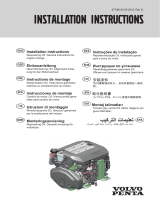
12
Presentation
D12D-C MH
1. Alternator
2. Expansion tank
3. Level glass, coolant
4. Coolant filler cap
5. Charge air cooler (located beneath
cover)
6. Air filter
7. Oil cooler, reverse gear
8. Crankcase breather filters
9. Heat exchanger
10. Control unit (located behind heat
exchanger)
11. Seawater pump
D12D-C MH
1. Exhaust pipe, dry
2. Turbocharger
3. Fine fuel filter with water trap
4. Emergency stop button
5. Oil filler cap
6. Coolant pump
7. Oil sump
8. Oil cooler, engine (loc. in engine
block)
9. Lubrication oil filter
10. By-pass filter for lubrication oil
11. Coolant filter
12. Oil dipstick, engine
13. Oil filler cap
14. Oil drain pump (optional)
15. Starter motor
16. Reverse gear Twin Disk MG5114 DC
1 2 3 4 5 6
7
891011
1 2 3 4
5
679
10
11
12
131516
14
8

13
Instruments
This chapter describes the instrument and control panels sold by Volvo Penta for your engine.
If you want to supplement the instrumentation, or if your boat is equipped with instruments not described here,
or you are not sure about their function, please contact your Volvo Penta dealer.
1. EVC system tachometer (with display)
2. Voltmeter
3. Oil pressure gauge
4. Temperature gauge
Ignition lock
A tab with the key code accompanies the ignition
keys, and is used to order extra ignition keys. Do not
store the code where it is accessible to unauthorized
persons.
S = Stop position.
0 = Key can be inserted and removed.
I = System voltage on (drive position).
II = Not used.
III = Start position.
IMPORTANT! Read the starting instructions in
the “Starting the engine” chapter.
2.
3.
4.
1.
Instruments
Start/stop panel
The start/stop panel is used to start or stop the engi-
ne. The starter key in the main control panel must be
in position “I” (driving position) for the engine to start.
The engine can only be stopped if the control panel
is activated.
IMPORTANT! Read the starting instructions in
the “Starting the engine” chapter.

14
Instruments
Alarm display (optional extra)
The following warning lamps should never light up during operation. On the other hand, the warning lamps light
up when the starter key is first turned to the drive position. Check that all lamps function. When the engine has
started, all lamps should have gone out. The lamps flash if the diagnostic function has registered malfunction.
When the fault has been acknowledged, the lamp gives continuous light.
NOTE! Warning lamps should never light up during operation
Oil pressure (red indication)
If the oil pressure lamp lights up during operation, the
oil pressure in the engine is too low. Stop the engine
at once.
Check the oil level in the engine. Please refer to
“Maintenance: Lubrication” to check and top the oil
up.
Also check that the oil filters are not blocked.
Please refer to “Maintenance: Lubrication system”
Please refer to the “If something happens” chapter,
and you will find detailed information about recom-
mended action in the “Diagnostic function” section.
WARNING! Continued operation when the oil
pressure is too low can cause serious engine
damage.
Water in fuel filter (orange indication)
If the lamp lights up, there is too much water in the
water trap in the fuel filters.
Empty the water trap underneath the secondary
fuel filter. Please refer to “Maintenance: Fuel sys-
tem”.
Please refer to the “In case of emergency” chapter,
and you will find detailed information about recom-
mended action in the “Diagnostic function” section.

15
Instruments
Battery (orange indication)
The battery lamp lights up if the alternator is not
charging. Stop the engine if this lamp lights up during
operation. If the lamp lights up, this can be due to a
fault in the electrical system or because the alterna-
tor drive belt is slack.
Check the alternator drive belts. Please refer to
“Maintenance: Engine, general”.
Also check that there is no poor contact/broken wires.
Please refer to the “If something happens” chapter,
and you will find detailed information about recom-
mended action in the “Diagnostic function” section.
WARNING! Do not continue operation if there
is any problem with the alternator drive belts.
This could cause serious engine damage.
Coolant temperature (red indication)
The coolant temperature lamp lights up when the
coolant temperature is too high. Stop the engine if
this lamp lights up during operation.
Check the coolant level. Please refer to “Mainte-
nance: Fresh water system”.
Check that the sea water filter is not blocked.
Please refer to “Maintenance: Sea water system”
Also check the impeller in the sea water pump.
Please refer to “Maintenance: Sea water system”.
Please refer to the “If something happens” chapter,
and you will find detailed information about recom-
mended action in the “Diagnostic function” section.
WARNING! Do not open the coolant filler cap
when the engine is warm, except in emergen-
cies. Steam or hot fluid could spray out.

16
Instruments
Coolant level (orange indication)
The coolant lamp lights up when the coolant level is
too low.
Check coolant level. Please refer to “Maintenan-
ce: Lubrication system”.
Please refer to the “If something happens” chapter,
and you will find detailed information about recom-
mended action in the “Diagnostic function” section.
Oil level (orange indication)
The oil level lamp lights up when the oil level is too
low.
Check the oil level. Please refer to “Maintenance:
Fresh water system”.
Please refer to the “If something happens” chapter,
and you will find detailed information about recom-
mended action in the “Diagnostic function” section.
Serious fault (red indication)
The lamp lights up when a serious fault occurs.
Please refer to the “If something happens” chapter,
and you will find detailed information about recom-
mended action in the “Diagnostic function” section.
Fault (orange indication)
The lamp lights up when a fault occurs.
Please refer to the “If something happens” chapter,
and you will find detailed information about recom-
mended action in the “Diagnostic function” section.

17
Instruments
Tachometer display selection (twin installa-
tion, port or starboard tachometer)
Is used to select which of the engines menu systems
should be navigable from the control panel. The
menu is shown on the display of the corresponding
engines tachometer. Select port or starboard.
Indication (red/green):
Off: Not possible to navigate in menu.
Lit: Possible to navigate in menu for selected en-
gine, port (red), starboard (green).
Multifunction button
Used to increase or decrease the instrument’s and
panel’s backlighting.
Depress the button for at least 1 second to turn the
backlighting on or off. The backlighting can be adjust-
ed in five stages by pressing the multifunction button.
If the button is pressed on a inactive control panel,
operating information is shown on the display(s) and
it is possible to navigate in the menus.
Back button
Used to back a step in the menu.
IMPORTANT! Always press the buttons firmly,
and for at least one second each time.
Activation button
Used to activate and lock the control panel and helm-
station.
Indication (red):
Off: Control panel not activated.
Lit: Control panel activated.
Flashes: Control panel not activated due to the con-
trol lever not being in neutral or the system has been
locked from another control panel.
Padlock
The padlock symbol lights if the control panel is
locked manually by depressing the -button, or if
exchange has been activated by routine ”Change of
control panel during journey”.
Lit: The system is locked and the engine can only be
controlled from the activated control panel.
Neutral button
Used to disengage the drive so that the engine speed
can be increased without driving (warming up).
Indication (green):
Off: Drive engaged.
Lit: Control lever in neutral position.
Flashes: Drive disengaged or system in calibration
mode.
Navigation wheel
Used to navigate through the menus shown on the
tachometer EVC system display. Navigate through
the menus by turning the wheel. Depress the wheel
to confirm a selection.
EVC control panel
The control panel is used in combination with the EVC system tachometer. The tachometer display shows oper-
ating information and menus that can be navigated from the control panel.

18
Instruments
EVC System Tachometer
Introduction
Volvo Penta EVC System Tachometer presents rel-
evant boat and engine information to the helmsman.
Information is presented on a display in the tachom-
eter.
Information is depending on engine model, number
of sensors and type of accessories.
Using the instrument
Start-up screen
This is the start-up screen for the EVC System Ta-
chometer. After a few seconds the first item in MAIN
MENU will appear.
Main menu
Navigating the menus
Navigate the menus by turning NAVIGATION WHEEL
clockwise or counter-clockwise. Views with a POIN-
TING HAND-symbol indicates a SUB-MENU. To enter
a SUB-MENU, push NAVIGATION WHEEL.
Speed (Optional)
Boat speed. Requires multisensor or GPS.
Water temp (Optional)
Water temperature. Requires multisensor.
Depth (Optional)
Water depth. Requires multisensor.
Trip menu (Optional)
Shows trip information. Requires the following:
- Multisensor or NMEA 0183/NMEA 2000 compat-
ible component (plotter, GPS, paddle wheel etc)
- Fuel level sender
- Trip computer software
Gauges menu
Shows data parameters.
Settings menu
The SETTINGS MENU allows the user to set various
options for the EVC System and to calibrate various
parameters.
Faults list
Number after word FAULTS indicates number of
faults stored in FAULTS LIST. List is reset when sys-
tem is rebooted.
NOTE! Faults list is not shown if no faults are registered.
Main menu structure
Trip menu
Gauges menu
Settings menu
Faults list
1/112