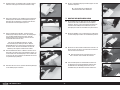
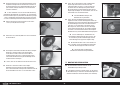
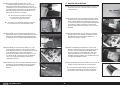
Hangar 9 HAN2765 Manuale del proprietario
- Categoria
- Giocattoli telecomandati
- Tipo
- Manuale del proprietario

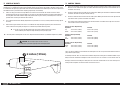
F6F-5 Hellcat 15cc
Instruction Manual
Bedienungsanleitung
Manuel d’utilisation
Manuale di Istruzioni

2
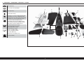
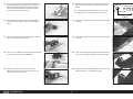
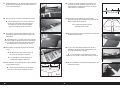
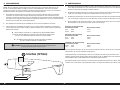
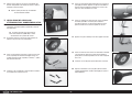
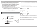
SPECIFICATIONS • SPEZIFIKATIONEN • SPÉCIFICATIONS • SPECIFICHE
64.0 in (1628 mm)
698.3 sq in (45.1 dm2) Total/Totale
47.8 in (1213 mm)
9–10 lbs (4.08–4.54 kg)
2-Stroke Gas: 15cc–20cc, 4-Stroke gas/petrol: 20cc
2-Takt Benziner: 15cc–20cc, 4-Takt Benzin: 20 cc
2 temps Essence: 15cc–20cc, 4 temps essence: 20cc
2-Tempi Gas: 15cc–20cc, 4 tempi benzina: 20 cc
Electric Power: Power 60, 470Kv Brushless
Elektro Antrieb Power: Power 60, 470Kv Brushless
Moteur électrique (EP): Power 60, 470Kv Brushless
Motore elettrico: Power 60, 470Kv Brushless
5-channel (or greater) with 5 servos
5-Kanal (oder größer) mit 5-Servos
5 voies (ou plus) avec 5 servos
a 5 canali (o più) con 5 servo
Spinner: 1-inch (Not Included)
Spinner: 25mm (Nicht enthalten)
Cône: 25mm (Non fourni)
Ogiva dell’elica: 25mm (Non inclusa)
5
7
/
8
inches (149mm)
B
A
C
D
E
O
F
F
G
H
I
J
K
L
M
N
P
Q
R
R
R

3
F6F-5 Hellcat 15cc
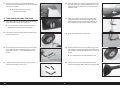
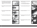
Part # English Deutsch Français Italiano
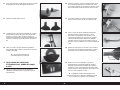
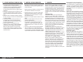
REPLACEMENT PARTS • ERSATZTEILE • PIÈCES DE RECHANGE • PEZZI DI RICAMBIO
A
HAN276501 Fuselage with Hatch Rumpf mit Haube Fuselage avec capot Fusoliera con portello
B
HAN276502 Left-Hand Wing with Aileron Linke Tragfl äche mit Querruder Aile gauche avec aileron Ala sinistra con alettone
C
HAN276503 Right-Hand Wing with Aileron Rechte Tragfl äche mit Querruder Aile droite avec aileron Ala destra con alettone
D
HAN276504 Stabilizer and Elevator Höhenruderset Set Plan horizontal et Gouverne de profondeur Set stabilizzatore ed elevatore
E
HAN276505 Fin and Rudder Finne u. Seitenruder Dérive et sa gouverne Direzionale e timone
F
HAN276506 Cowling Motorhaube Capot moteur Carenatura
G
HAN276507 Top Hatch Obere Abdeckung Trappe supérieure Portello superiore
H
HAN276508 Canopy Kabinenhaube Verrière Calotta
I
HAN276509 Painted Pilot Lackierter Pilot Pilote peint Pilota verniciato
J
HAN276510 Pushrod Set Gestänge / Anlenkungen Set Jeu de tringleries Set dell’asta di spinta
K
HAN276511 Hardware Set Kleinteile Set Sachet de visserie Set dei pezzi
L HAN276512 Wheels, 3
1
/
2
-inch Räder, 89mm Roues, 89mm Ruote, 89 mm
M
HAN276514 Tailwheel Assembly Spornrad m. Zbh. Assemblage de roulette de queue Gruppo del ruotino di coda
N
HAN276515 Landing Gear Wire Struts Fahrwerk-Verstrebung Jambes à fi l du train d’atterrissage Gambe a fi lo per carrello di atterraggio
0 HAN276516 Wing Tube Tragfl ächenverbinder Clé d’aile Tubo dell’ala
P
HAN276517 Fuel Tank Kraftstofftank Réservoir de carburant Serbatoio del carburante
Q
HAN276518 EP Motor Box EP-Motorkasten Boîtier du moteur EP Vano motore elettrico
R
HAN276519 Scale Parts Maßstabsgetreue Details Pièces de détails à l’échelle Dettagli in scala
SMALL PARTS (NOT SHOWN) • KLEINTEILE (NICHT ABGEBILDET) • PETITES PIÈCES (NON REPRÉSENTÉES) • PARTI DI PICCOLE DIMENSIONI (NON MOSTRATE)
HAN276513 Decal Set Dekorbogen Planche de décoration Set di decalcomanie
REQUIRED RADIO EQUIPMENT • ERFORDERLICHE RC AUSRÜSTUNG • ÉQUIPEMENT RADIO REQUIS • APPARECCHIATURE RADIO NECESSARIE
SPMAR636 AR636 6-Ch AS3X Sport Receiver AR636 AS3X-Sportempfänger mit 6Kanälen Récepteur AR636 AS3X Sport 6canaux Ricevitore AR636 AS3X Sport a 6 canali
SPMA3002 (2) Heavy-Duty Servo Extension 9-inch Servokabelverlängerung 230 mm (9 inch) Rallonge de servo, 230 mm Estensione servo 9 pollici
SPMA3008 Heavy-Duty Y-Harness 6-inch Heavy Duty Y-Kabelbaum, 152mm (6Zoll) Harnais résistant en Y de 15 cm (6 po) Prolunga a Y Heavy Duty, 15 cm
SPMA3054 Servo Connector Clips (25) Servosteckerklemmen (25) Attaches de connexion du servo (25) Morsetti servocomando (25)
SPMSA6110 (5) A6110 HV Standard Servo A6110 HV Standard Servo Servo standard A6110 HV Servo standard A6110 HV

4
Part # English Deutsch Français Italiano
2-STROKE GAS • 2-TAKT BENZINER • 2 TEMPS ESSENCE • 2-TEMPI A BENZINA
EVOE15GX2 15GX Gas Engine with Pumped Carb 15GX 15cc Benzinmotor Moteur essence 15GX 15cc Motore a benzina 15GX 15cc
EVOM9 15cc Inverted Wraparound Muffl er 15cc invertierte Wraparound-Schalldämpfer Silencieux global inversé 15cc Silenziatore invertito, avvolgente, 15cc
HAN279012 1-inch Spinner Nut 5/16-24: P-47D-1 1-Zoll Spinner-Mutter, 5/16-24: P-47D-1 Écrou de cône de 2,54 cm (1 po), 5/16-24: P-47D-1 Dado dell’ogiva da 2,54 mm 5/16-24: P-47D-1
APC14060 Competition Propeller, 14 x 6 Competition Propeller, 14 x 6 Hélice 14 x 6 Competition Elica da competizione, 14 x 6
SPMSA6110 (5) A6110 HV Standard Servo A6110 HV Standard Servo Servo standard A6110 HV Servo standard A6110 HV
DUB799 Tygon Gas Tubing, 3-foot Medium Tygon-Gasrohre, 1 m (3 Fuß) m Durchschnitt Tube à essence Tygon, 91,4 cm (3 pi) moyen Tubo per carburante Tygon, 3 piedi, medio
HAN116 Fuel Filler with “T” and Overfl ow Fitting Hangar 9 Tanknippel mit T Stück u. Überlauf Fitting Point de remplissage de carburant avec coupleur en T Bocchettone di riempimento carburante con
SPM9530 Spektrum™ 3-Wire Switch Harness Spektrum™ dreiadriges Schalterkabel Câblage d’interrupteur 3 fi ls Spektrum™ Interruttore di accensione a 3 fi li Spektrum™
EVOA112 (2) Evolution 3 Wire Ignition/Receiver Switch Evolution Zündschalter Interrupteur Evolution 3 fi ls Allumage/RX
Evolution, interruttore a 3 fi li accensione/
ricevitore
SPMB2000LPRX 2000mAh 2S 7.4V LiPo Receiver Battery LiPo-Empfängerakku (7,4 V / 2000 mAh) Batterie Li-Po de récepteur 7,4 V 2000 mAh Batteria per ricevitore da 7,4 V Li-Po, 2.000 mAh
SPMB4000LPRX 4000mAh 2S 7.4V LiPo Receiver Battery LiPo-Empfängerakku (7,4 V / 4000 mAh) Batterie Li-Po de récepteur 7,4 V 4000 mAh Batteria per ricevitore da 7,4 V Li-Po, 4.000 mAh
ELECTRIC POWER • ELEKTROANTRIEB • MOTEUR ELECTRIQUE (EP) • MOTORE ELETTRICO
EFLM4060B Power 60 BL Outrunner Motor, 470Kv Bürstenloser Außenläufer-Motor Leistung 60, 470Kv
Moteur à cage tournante sans balais
Power 60 de 470Kv
Motore brushless a cassa rotante
Power 60, 470Kv
CSE010009700 Talon 90-Amp 25V BL ESC W/20amp BEC
Talon 90 A 25 V bürstenloser Geschwindigkeitsregler
mit 20 A BEC
Variateur ESC Talon 90 A 25 V BL avec BEC 20 A ESC BL Talon 90-Amp 25 V con BEC 20amp
KXSB0029 7000mAh 6S 22.2V 30C LiPo, 10AWG: EC5 7000 mA 6S 22,2 V 30C LiPo-Akku,10 AWG EC5
Batterie Li-Po 6S 22,2V 7000mA 30C, 10AWG prise
EC5
Batteria LiPo 30C 22,2V 6S 7000 mAh,10AWG
EC5
APC16080E Electric Propeller, 16 x 8E Elektro Propeller, 16 x 8E Hélice électrique, 16 x 8E Elica elettrica sottile, 16 x 8E
HAN279011 1-inch Spinner Nut 8 x 1.25: P-47D-1 1-Zoll Spinner-Mutter, 8 x 1,25: P-47D-1 Écrou de cône de 2,54 cm (1 po), 8 x 1,25: P-47D-1 Dado dell’ogiva da 2,54 mm 8 x 1,25: P-47D-1
SPMSA6110 (4) A6110 HV Standard Servo A6110 HV Standard Servo Servo standard A6110 HV Servo standard A6110 HV
EFLAEC506 EC5 Extension Lead with 6-inch Wire, 10Awg EC5 Verlängerungsleitung mit 6-Zoll-Kabel, 10Awg Rallonge EC5 avec fi l de 15 cm (6 po), 10 AWG
Cavo di prolunga EC5 con fi lo da 15,24 cm, 10
AWG
SPMA3003 Heavy-Duty Servo Extension 12-inch Servokabelverlängerung 300 mm (12 inch) Rallonge de servo, 300 mm Estensione servo 12 pollici
OPTIONAL ELECTRIC RETRACTS • OPTIONALES ELEKTRISCHES EINZIEHFAHRWERK • TRAINS RÉTRACTABLES ÉLECTRIQUES OPTIONNELS • ELEMENTI RETRATTILI ELETTRICI OPZIONALI
EFLG520 60-120 95-Degree Electric Rotating Retracts
60–120 95° drehbare, elektrische Einfahrvorrichtungen
Système de rentrée rotatif électrique 60–120
95degrés
Elemento retrattile rotante elettrico 60–120, 95
gradi
EFLG520F4U F4U Shock-Absorbing Strut Set F4U Dämpferstreben Set Paire de jambes amorties pour F4U Set gambe ammortizzate F4U
SPMA3001 (2) Heavy-Duty Servo Extension 3-inch Servokabelverlängerung 75 mm (3 inch) Rallonge de servo, 75 mm Estensione servo 3 pollici
REQUIRED ADHESIVES • ERFORDERLICHE KLEBSTOFFE • TYPES DE COLLES • ADESIVI NECESSARI
DLMAD44 Roket Rapid CA 5-10 sec: 20g Roket Rapid CA 5-10 s: 20g Colle cyano Roket Rapid 5-10 sec: 20g Colla cianoacrilica Roket Rapid 5-10 sec: 20 g
DLMAD45 Roket Max CA 10-20 sec: 20g Roket Max CA 10-20 s: 20g Colle cyano Roket Max 10-20 sec: 20g Colla cianoacrilica Roket Max 10-20 sec: 20 g
PAAPT715 CA Accelerator Sekundenkleber (CA) Aktivator Accélérateur de colle CA Accelerante colla CA
PAAPT37 5-Minute Epoxy 5 Minuten Epoxy Époxy 5 minutes Colla epossidica 5 minuti
PAAPT35 15-Minute Epoxy 15 Minuten Epoxy Époxy 15 minutes Colla epossidica 15 minuti
PAAPT42 Threadlock Schraubensicherungslack Frein-fi let Frenafi letti
DLMAD12 R/C Modeller Canopy Glue: 4 oz R/C Modeller Kanzelkleber: 113,4g (4 oz) Colle à verrière R/C Modeller: 113g Colla per capottine R/C Modeller: 4 oz

5
F6F-5 Hellcat 15cc
Part # English Deutsch Français Italiano
REQUIRED TOOLS • BENÖTIGTES WERKZEUG • OUTILS REQUIS • ATTREZZI NECESSARI
C-clamp Schraubzwinge Serre joint Morsetto a C
Drill Bohrer Mini-perceuse Trapano
Drill bit: 1/16-inch, 5/64-inch, 3/32-inch,
1/8-inch, 9/64-inch, 5/32-inch, 11/64-inch,
3/16-inch, 13/64-inch, 7/32-inch
Bohrer: 1,5mm, 2mm, 2,5mm, 3mm, 3,5mm, 4mm,
4,5mm, 5mm, 5,5mm, 6mm
Forêt : 1,5mm, 2mm, 2,5mm, 3mm, 3,5mm, 4mm,
4,5mm, 5mm, 5,5mm, 6mm
Punte per trapano: 1,5mm, 2mm, 2,5mm, 3mm,
3,5mm, 4mm, 4,5mm, 5mm, 5,5mm, 6mm
Felt-tipped pen Faserstift Feutre fi n effaçable Pennarello
Epoxy brush Pinsel Pinceau Epoxy Spazzole epoxy
Flat fi le Flachfeile Lime plate Lima piatta
Hemostats Klemme Pince Hemostat Pinzetta
Hex wrench: 1.5mm, 2mm, 2.5mm, 3mm Inbusschlüssel: 1,5mm, 2mm, 2,5mm, 3mm Tournevis hexagonal: 1,5mm, 2mm, 2,5mm, 3mm Chiave esag.: 1,5mm, 2mm, 2,5mm, 3mm
Hobby knife with #11 blade Hobbymesser mit # 11 Klinge Couteau : Lame numéro 11 Taglierino: #11 lama
Hook and loop tape Klettband Bande auto-agrippante Nastro a strappo
Hook and loop straps Klettgurt Bandes auto-agrippante Fascette a strappo
Isopropyl alcohol Isopropyl Alkohol Alcool isopropylique Alcol isopropilico
Low-tack tape Kreppband Adhésif de masquage Nastro a bassa aderenza
Needle nose pliers Spitzzange Pince fi ne Pinze a becco stretto
Mixing cups and sticks Mischbecher und Rührstäbchen Récipients pour mélanger et bâtons Contenitori e stick per mixer colla
Nut driver: 7mm Steckschlüssel. 7mm Clés à douilles : 7mm Chiave per dadi: 7mm
Paper towels Papiertücher Papier absorbant Asciugamani di carta
Pencil Stift Crayon à papier Matita
Phillips screwdriver: #1, #2 Phillips Schraubendreher: #1, #2 Tournevis cruciforme: #1, #2 Cacciavite a croce: #1, #2
Pin vise Handbohrer Porte forets Trapano manuale
Pliers Zange Pince Pinze
Ruler Lineal Réglet Righello
Sandpaper Schleifpapier Papier de verre Carta vetrata
Scissors Schere Ciseaux Forbici
Side cutters Seitenschneider Pince coupante Lama laterale
Square Geodreieck Équerre Squadra
Tapered reamer Zulaufende Reibahle Alésoir conique Alesatore rastremato
Tie wraps Kabelbinder Colliers Fascette avvolgenti
T-pins T- Nadeln Epingles Spilli a T
Toothpicks Zahnstocher Cure dents Stuzzicadenti
Tubing bender Rohrbieger Cintreuse Curvatubi
Vise grips Klemmen Pince-étau Pinze bloccanti
OPTIONAL ITEMS • OPTIONALE TEILE • ÉLÉMENTS OPTIONNELS • ARTICOLI OPZIONALI
SPMAR7350 AR7350 7 Channel AS3X Receiver AR7350 AS3X-Empfänger mit 7Kanälen Récepteur AS3X 7 canaux AR7350 Ricevitore AS3X a 7 canali AR7350
SPMSA6150 A6150 H-T / H-S Standard HV Servo A6150 H-T/H-S HV-Standard-Servo Servo A6150 H-T/H-S Standard HV Servo HV standard H-T / H-S A6150
EVOA100 Optical Ignition Kill Switch Optischer Zünd-Notausschalter Coupe-circuit optique d’allumage Sezionatore ottico accensione
SPMA3000 (2) Heavy-Duty Servo Extension 3-inch Servokabelverlängerung 75 mm (3 inch) Rallonge de servo, 75 mm Estensione servo 3 pollici
EVOE20GX2 20GX Gas Engine with Pumped Carb 20GX 20cc (1.20 cu. in.) Benzinmotor Moteur essence 20GX 20cc Motore a benzina 20GX 20cc (1.20 cu. in.)
APC16060 Competition Propeller, 16 x 6 Competition Propeller, 16 x 6 Hélice 16 x 6 Competition Elica da competizione, 16 x 6

6
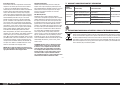
NOTICE
All instructions, warranties and other collateral documents are subject to change at the sole discretion of Horizon
Hobby, LLC. For up-to-date product literature, visit horizonhobby.com and click on the support tab for this product.
The following terms are used throughout the product literature to indicate various levels of potential harm when
operating this product:
Meaning of Special Language
WARNING: Procedures, which if not properly followed, create the probability of property damage, collateral damage,
and serious injury OR create a high probability of superfi cial injury.
CAUTION: Procedures, which if not properly followed, create the probability of physical property damage AND a
possibility of serious injury.
NOTICE: Procedures, which if not properly followed, create a possibility of physical property damage AND a little or
no possibility of injury.
WARNING: Read the ENTIRE instruction manual to become familiar with the features of the product before operating.
Failure to operate the product correctly can result in damage to the product, personal property and cause serious
injury.
This is a sophisticated hobby product. It must be operated with caution and common sense and requires some basic
mechanical ability. Failure to operate this Product in a safe and responsible manner could result in injury or damage
to the product or other property. This product is not intended for use by children without direct adult supervision. Do
not attempt disassembly, use with incompatible components or augment product in any way without the approval
of Horizon Hobby, LLC. This manual contains instructions for safety, operation and maintenance. It is essential to
read and follow all the instructions and warnings in the manual, prior to assembly, setup or use, in order to operate
correctly and avoid damage or serious injury.
AGE RECOMMENDATION: NOT FOR CHILDREN UNDER 14 YEARS. THIS IS NOT A TOY.
USING THE MANUAL
This manual is divided into sections to help make assembly easier to understand.
SAFETY WARNINGS AND PRECAUTIONS
Read and follow all instructions and safety precautions before use. Improper use can result in fi re, serious injury and
damage to property.
Components
Use only with compatible components. Should any compatibility questions exist, please refer to the product
instructions, component instructions or contact the appropriate Horizon Hobby offi ce.
Flight
Fly only in open areas to ensure safety. It is recommended fl ying be done at radio control fl ying fi elds. Consult local
ordinances before choosing a fl ying location.
Propeller
Keep loose items that can become entangled in the propeller away from the prop. This includes loose clothing or other
objects such as pencils and screwdrivers. Keep your hands away from the propeller as injury can occur.
Batteries
Always follow the manufacturer’s instructions when using and disposing of any batteries. Mishandling of Li-Po
batteries can result in fi re causing serious injury and damage.
Small Parts
This kit includes small parts and should not be left unattended near children as choking and serious injury could result.
SAFE OPERATING RECOMMENDATIONS
• Inspect your model before every fl ight to ensure it is airworthy.
• Be aware of any other radio frequency user who may present an interference problem.
• Always be courteous and respectful of other users in your selected fl ight area.
• Choose an area clear of obstacles and large enough to safely accomodate your fl ying activity.
• Make sure this area is clear of friends and spectators prior to launching your aircraft.
• Be aware of other activities in the vicinity of your fl ight path that could cause potential confl ict.
• Carefully plan your fl ight path prior to launch.
• Abide by any and all established AMA National Model Aircraft Safety Code.
BEFORE STARTING ASSEMBLY
• Remove parts from bag.
• Inspect fuselage, wing panels, rudder and stabilizer for damage.
• If you fi nd damaged or missing parts, contact your place of purchase.
• Charge transmitter and receiver batteries.
• Center trims and sticks on your transmitter.
• For a computer radio, create a model memory for this particular model.
• Bind your transmitter and receiver, using your radio system’s instructions.
IMPORTANT: Rebind the radio system once all control throws are set. This will keep the servos from moving to
their endpoints until the transmitter and receiver connect. It will also guarantee the servo reversal settings are
saved in the radio system.
FAA INFORMATION
If you own this product, you may be required to register with the FAA.
For up-to-date information on how to register with the FAA, please visit https://registermyuas.faa.gov/.
For additional assistance on regulations and guidance on UAS usage, visit knowbeforeyoufl y.org/.
BUILDING PRECAUTIONS
During assembly, we recommend resting the parts on a soft surface such as a soft towel to help prevent denting the
sheeting.

7
F6F-5 Hellcat 15cc
Propeller
Halten Sie lose Gegenstände die sich im Propeller verfangen können weg vom Propeller. Dieses gilt auch für Kleidung
oder andere Objekte wie zum Beispiel Stifte oder Schraubendreher.
Halten Sie ihre Hände weg vom Propeller, es besteht akute Verletzungsgefahr.
Akkus
Folgen Sie immer den Herstelleranweisungen bei dem Gebrauch oder Entsorgung von Akkus. Falsche Behandlung von
LiPo Akkus kann zu Feuer mit Körperverletzungen und Sachbeschädigung führen.
Kleinteile
Dieser Baukasten beinhaltet Kleinteile und darf nicht unbeobachtet in der Nähe von Kindern gelassen werden, da die
Teile verschluckt werden könnten mit ernsthaften Verletzung zur Folge.
EMPFEHLUNGEN ZUM SICHEREN BETRIEB
• Überprüfen Sie zur Flugtauglichkeit ihr Modell vor jedem Flug.
• Beachten Sie andere Piloten deren Sendefrequenzen ihre Frequenz stören könnte.
• Begegnen Sie anderen Piloten in ihrem Fluggebiet immer höfl ich und respektvoll.
• Wählen Sie ein Fluggebiet, dass frei von Hindernissen und groß genug ist.
• Stellen Sie vor dem Start sicher, dass die Fläche frei von Freunden und Zuschauern ist.
• Beobachten Sie den Luftraum und andere Flugzeuge/Objekte die ihren Flugweg kreuzen und zu einem Konfl ikt
führen könnten.
• Planen Sie sorgfältig ihren Flugweg vor dem Start.
VOR DEM ZUSAMMENBAU
• Entnehmen Sie zur Überprüfung jedes Teil der Verpackung.
• Überprüfen Sie den Rumpf, Tragfl ächen, Seiten- und Höhenruder auf Beschädigung.
• Sollten Sie beschädigte oder fehlende Teile feststellen, kontaktieren Sie bitte den Verkäufer.
• Laden des Senders und Empfängers.
• Zentrieren der Trimmungen und Sticks auf dem Sender.
• Sollten Sie einen Computersender verwenden, resetten Sie einen Speicherplatz und benennen ihn nach dem Modell.
• Sender und Empfänger jetzt nach den Bindeanweisung des Herstellers zu binden.
WICHTIG: Wir empfehlen dringend nachdem alle Einstellungen vorgenommen worden sind, das Modell neu zu binden.
Dieses verhindert, dass die Servos in die Endanschläge laufen bevor sich Sender und Empfänger verbunden haben. Es
garantiert auch, dass die Servoreverseeinstellungen in der RC Anlage gesichert sind.
HINWEISE ZUM BAU
Während des Zusammenbaus empfehlen wird, dass die Teile auf einer weichen Oberfl äche, wie einem Handtuch,
abgelegt werden, um ein Eindrücken der Bleche zu verhindern.
HINWEIS
Alle Anweisungen, Garantien und anderen zugehörigen Dokumente können im eigenen Ermessen von Horizon Hobby,
LLC. jederzeit geändert werden Die aktuelle Produktliteratur fi nden Sie auf horizonhobby.com unter der Registerkarte
„Support“ für das betreffende Produkt.
Spezielle Bedeutungen
Die folgenden Begriffe werden in der gesamten Produktliteratur verwendet, um auf unterschiedlich hohe
Gefahrenrisiken beim Betrieb dieses Produkts hinzuweisen:
WARNUNG: Wenn diese Verfahren nicht korrekt befolgt werden, ergeben sich wahrscheinlich Sachschäden,
Kollateralschäden und schwere Verletzungen ODER mit hoher Wahrscheinlichkeit oberfl ächliche Verletzungen.
ACHTUNG: Wenn diese Verfahren nicht korrekt befolgt werden, ergeben sich wahrscheinlich Sachschäden UND die
Gefahr von schweren Verletzungen.
HINWEIS: Wenn diese Verfahren nicht korrekt befolgt werden, können sich möglicherweise Sachschäden UND geringe
oder keine Gefahr von Verletzungen ergeben.
WARNUNG: Lesen Sie die GESAMTE Bedienungsanleitung, um sich vor dem Betrieb mit den Produktfunktionen
vertraut zu machen. Wird das Produkt nicht korrekt betrieben, kann dies zu Schäden am Produkt oder persönlichem
Eigentum führen oder schwere Verletzungen verursachen.
Dies ist ein hochentwickeltes Hobby-Produkt. Es muss mit Vorsicht und gesundem Menschenverstand betrieben
werden und benötigt gewisse mechanische Grundfähigkeiten. Wird dieses Produkt nicht auf eine sichere und
verantwortungsvolle Weise betrieben, kann dies zu Verletzungen oder Schäden am Produkt oder anderen Sachwerten
führen. Dieses Produkt eignet sich nicht für die Verwendung durch Kinder ohne direkte Überwachung eines
Erwachsenen. Verwenden Sie das Produkt nicht mit inkompatiblen Komponenten oder verändern es in jedweder Art
ausserhalb der von Horizon Hobby, LLC vorgegebenen Anweisungen. Diese Bedienungsanleitung enthält Anweisungen
für Sicherheit, Betrieb und Wartung. Es ist unbedingt notwendig, vor Zusammenbau, Einrichtung oder Verwendung
alle Anweisungen und Warnhinweise im Handbuch zu lesen und zu befolgen, damit es bestimmungsgemäß betrieben
werden kann und Schäden oder schwere Verletzungen vermieden werden.
NICHT GEEIGNET FÜR KINDER UNTER 14 JAHREN. DIES IST KEIN SPIELZEUG.
ÜBER DIESE ANLEITUNG
Diese Anleitung ist zur Vereinfachung des Zusammenbaues in Sektionen unterteilt.
WARNUNGEN UND SICHERHEITS-VORKEHRUNGEN
Bitte lesen und befolgen Sie alle Anweisungen und Sicherheitsvorkehrungen vor dem Gebrauch. Falscher, nicht
sachgemäßer Gebrauch kann Feuer, ernsthafte Verletzungen und Sachbeschädigungen zur Folge haben.
Komponenten
Verwenden Sie mit dem Produkt nur kompatible Komponenten. Sollten Fragen zur Kompatibilität auftreten, lesen Sie
bitte die Produkt- oder Bedienungsanweisung oder kontaktieren den Service von Horizon Hobby.
Fliegen
Fliegen Sie um Sicherheit garantieren zu können, nur in weiten offenen Gegenden. Wir empfehlen hier den Betrieb auf
zugelassenen Modellfl ugplätzen. Bitte beachten Sie lokale Vorschriften und Gesetze, bevor Sie einen Platz zum Fliegen
wählen.

8
L’hélice
Gardez éloignés tous les éléments qui pourraient être attrapés par l’hélice. Cela inclut les vêtements larges ou les
objets comme des outils par exemple. Gardez toujours vos mains à distance pour éviter tout cas de blessures.
Les batteries
Suivez toujours les instructions du fabricant de vos batteries. Une mauvaise manipulation d’une batterie Li-Po peut
entraîner un incendie causant de graves dégâts matériels et des blessures corporelles.
Petites pièces
Ce kit contient des petites pièces qui ne doivent pas être laissées à la portée des enfants, ces pièces sont dangereuses
pour eux et peuvent entraîner de graves blessures.
CONSIGNES DE SÉCURITÉ CONCERNANT L’UTILISATION
• Inspectez votre modèle avant chaque vol.
• Surveillez les fréquences utilisées à proximité.
• Soyez toujours courtois et respectueux des autres utilisateurs de la zone de vol.
• Choisissez une zone dégagée de tout obstacle et suffi samment grande pour voler en toute sécurité.
• Contrôlez que la zone est libre de spectateurs avant de lancer votre modèle.
• Soyez conscient des autres activités aux alentours de votre vol, risque de confl it potentiel.
• Planifi ez votre vol avant de le commencer.
AVANT DE COMMENCER L’ASSEMBLAGE
• Retirez toutes les pièces des sachets pour les inspecter.
• Inspectez soigneusement le fuselage, les ailes et les empennages.
• Si un élément est endommagé, contactez votre revendeur.
• ll est recommandé de préparer tous les éléments du système de la radio.
• Cela inclut la charge des batteries comme la mise au neutre des trims et des manches de votre émetteur.
• Si vous utilisez une radio programmable, sélectionnez une mémoire libre afi n d’y enregistrer les paramètres de ce
modèle.
• Nous vous recommandons d’affecter maintenant le récepteur à l’émetteur en suivant les instructions fournies avec
votre radio.
IMPORTANT: Il est hautement recommandé de ré-affecter le système une fois que les courses seront réglées. Cela
empêchera les servos d’aller en butée lors de la connexion du système. Cela garantit également que la direction des
servos est enregistrée dans l’émetteur.
PRÉCAUTIONS D’ASSEMBLAGE
Lors de l’assemblage de votre modèle, nous vous recommandons de poser les pièces sur une surface douce comme
une serviette douce pour éviter d’abîmer l’entoilage.
REMARQUE
La totalité des instructions, garanties et autres documents est sujette à modifi cation à la seule discrétion d’Horizon
Hobby, LLC. Pour obtenir la documentation àjour, rendez-vous sur le site horizonhobby.com et cliquez sur l’onglet de
support de ce produit.
Signifi cation de certains termes spécifi ques
Les termes suivants sont utilisés dans l’ensemble du manuel pour indiquer différents niveaux de danger lors de
l’utilisation de ce produit:
AVERTISSEMENT: Procédures qui, si elles ne sont pas suivies correctement, peuvent entraîner des dégâts matériels
et des blessures graves OU engendrer une probabilité élevée de blessure superfi cielle.
ATTENTION: Procédures qui, si elles ne sont pas suivies correctement, peuvent entraîner des dégâts matériels ET des
blessures graves.
REMARQUE: Procédures qui, si elles ne sont pas suivies correctement, peuvent entraîner des dégâts matériels ET
éventuellement un faible risque de blessures.
AVERTISSEMENT: Lisez la TOTALITÉ du manuel d’utilisation afi n de vous familiariser avec les caractéristiques du
produit avant de le faire fonctionner. Une utilisation incorrecte du produit peut entraîner sa détérioration, ainsi que des
risques de dégâts matériels, voire de blessures graves.
Ceci est un produit de loisirs sophistiqué. Il doit être manipulé avec prudence et bon sens et requiert des aptitudes
de base en mécanique. Toute utilisation irresponsable de ce produit ne respectant pas les principes de sécurité peut
provoquer des blessures, entraîner des dégâts matériels et endommager le produit. Ce produit n’est pas destiné à
être utilisé par des enfants sans la surveillance directe d’un adulte. N’essayez pas de modifi er ou d’utiliser ce produit
avec des composants incompatibles hors des instructions fournies par Horizon Hobby, LLC. Ce manuel comporte des
instructions relatives à la sécurité, au fonctionnement et à l’entretien. Il est capital de lire et de respecter la totalité
des instructions et avertissements du manuel avant l’assemblage, le réglage et l’utilisation, ceci afi n de manipuler
correctement l’appareil et d’éviter tout dégât matériel ou toute blessure grave.
14 ANS ET PLUS. CECI N’EST PAS UN JOUET.
UTILISATION DU MANUEL
Ce manuel est divisé en sections pour vous aider à comprendre plus facilement l’assemblage.
AVERTISSEMENTS RELATIFS À LA SÉCURITÉ
Lisez et suivez toutes les instructions relatives à la sécurité avant utilisation. Une utilisation inappropriée peut entraîner
un incendie, de graves blessures et des dégâts matériels.
Composants
Utilisez uniquement des composants compatibles. Si vous avez des questions concernant la compatibilité, référez-vous
à ce manuel ou contactez le service technique Horizon Hobby.
Le vol
Volez uniquement dans des zones dégagées pour un maximum de sécurité. Il est recommandé d’utiliser les pistes des
clubs d’aéromodélisme. Consultez votre mairie pour connaître les sites autorisés.

9
F6F-5 Hellcat 15cc
AVVISO
Tutte le istruzioni, le garanzie e gli altri documenti pertinenti sono soggetti a cambiamenti a totale discrezione di
Horizon Hobby, LLC. Per una documentazione aggiornata sul prodotto, visitare il sito www.horizonhobby.com e fare
clic sulla sezione Support per questo prodotto.
Signifi cato dei termini particolari
In tutta la documentazione relativa al prodotto sono utilizzati iseguenti termini per indicare vari livelli di potenziale
pericolo durante il funzionamento:
AVVERTENZA: Procedure che, se non debitamente seguite, espongono alla possibilità di danni alla proprietà fi sica
opossono omportare un’elevata possibilità di provocare ferite superfi ciali. Ulteriori precauzioni per la sicurezza e
avvertenze.
ATTENZIONE: Procedure che, se non sono seguite correttamente, possono creare danni materiali E possibili gravi
lesioni.
AVVISO: Procedure che, se non sono seguite correttamente, possono creare danni materiali E nessuna oscarsa
possibilità di lesioni.
AVVERTENZA: Leggere TUTTO il manuale di istruzioni e prendere familiarità con le caratteristiche del prodotto, prima
di farlo funzionare. Un utilizzo scorretto del prodotto può causare danni al prodotto stesso, alle persone oalle cose,
provocando gravi lesioni.
Questo è un prodotto di hobbistica sofi sticato e NON un giocattolo. È necessario farlo funzionare con cautela e
responsabilità e avere conoscenze basilari di meccanica. Se questo prodotto non è utilizzato in maniera sicura e
responsabile potrebbero verifi carsi lesioni odanni al prodotto stesso oad altre proprietà. Non è un prodotto adatto
aessere utilizzato dai bambini senza la diretta supervisione di un adulto. Non usare componenti non compatibili
o alterare il prodotto in nessuna maniera al di fuori delle istruzioni fornite da Horizon Hobby, LLC. Questo manuale
contiene le istruzioni per un funzionamento e una manutenzione sicuri. È fondamentale leggere e seguire tutte le
istruzioni e le avvertenze del manuale prima di montare, confi gurare ofar funzionare il Prodotto, al fi ne di utilizzarlo
correttamente e di evitare danni olesioni gravi.
MINIMO 14 ANNI. NON È UN GIOCATTOLO.
COME USARE IL MANUALE
Questo manuale è diviso in sezioni per rendere più facile la comprensione del montaggio.
AVVERTIMENTI E PRECAUZIONI PER LA SICUREZZA
Prima dell’uso leggere attentamente tutte le istruzioni e le precauzioni per la sicurezza. In caso contrario si potrebbero
procurare incendi, danni o ferite.
Componenti
Usare solo componenti compatibili. Se ci fossero dubbi riguardo alla compatibilità, è opportuno far riferimento alle
istruzioni relative al prodotto o ai componenti oppure rivolgersi al reparto Horizon Hobby di competenza.
Volo
Per sicurezza volare solo in aree molto ampie. Meglio se in campi volo autorizzati per modellismo. Consultare le
ordinanze locali prima di scegliere luogo dove volare.
Elica
Tenere gli oggetti liberi (vestiti, penne, cacciaviti, ecc.) lontano dall’elica, prima che vi restino impigliati. Bisogna fare
attenzione anche con le mani perché c’è il rischio di ferirsi anche gravemente.
Batterie
Quando si maneggiano o si utilizzano le batterie, bisogna attenersi alle istruzioni del costruttore; il rischio è di procurare
incendi, specialmente con le batterie LiPo, con danni e ferite serie.
Piccole parti
Questo kit comprende delle parti di piccole dimensioni e non lo si può lasciare incustodito se c’è la presenza di bambini
che li possono inghiottire e rimanere soffocati o intossicati.
RACCOMANDAZIONI PER OPERARE IN SICUREZZA
• Controllare attentamente il modello prima di ogni volo per accertarsi che sia idoneo.
• Essere consapevoli che un altro utente della frequenza in uso, potrebbe procurare delle interferenze.
• Essere sempre cortesi e rispettosi nei confronti degli altri utilizzatori dell’area in cui ci si trova.
• Scegliere un’area libera da ostacoli e abbastanza ampia da permettere lo svolgimento del volo in sicurezza.
• Prima del volo verifi care che l’area sia libera da amici e spettatori.
• Stare attenti alle altre attività che si svolgono in vicinanza della vostra traiettoria di volo, per evitare possibili confl itti.
• Pianifi care attentamente il volo prima di lanciare il modello.
• Rispettare sempre scrupolosamente le regole stabilite dall’associazione locale.
PRIMA DI INIZIARE IL MONTAGGIO
• Togliere tutti i pezzi dalla scatola.
• Verifi care che la fusoliera, l’ala e i piani di coda non siano danneggiati.
• Se si trovano parti danneggiate, contattare il negozio da cui è stato acquistato.
• Caricare il trasmettitore e la batteria di volo.
• Centrare stick e trim sul trasmettitore.
• Con una radio computerizzata creare una nuova memoria per questo modello.
• Facendo riferimento alle istruzioni del radiocomando, connettere (bind) trasmettitore e ricevitore.
IMPORTANTE: Ripetere la procedura di connessione una volta regolate le corse, per evitare che i servi vadano a fi ne
corsa. Garantirà anche che le impostazioni di inversione del servo vengano salvate nel sistema radio.
PRECAUZIONI PER LA COSTRUZIONE
Durante l’assemblaggio noi consigliamo di appoggiare le varie parti su di una superfi cie morbida come un
asciugamano di spugna per evitare ammaccature al rivestimento.

10
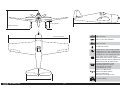
TRANSPORTATION AND STORAGE
Use the 3-view drawing at the back of this manual to
determine the amount of space required to transport and
store your model. The model can be disassembled, so the
amount of room necessary can vary. We recommend the
use of a wing bag to help protect these surfaces during
transport and storage. The control horns and linkages can
also cause damage to nearby surfaces even when placed
in storage bags. Always place surfaces so the tops are
together to prevent damage from the control horns and
linkages.
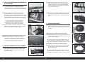
ENGINE SELECTION
We recommend the 15cc Evolution
®
engine for this
model. It provides great performance and more than
scale aerobatic capability. We understand some of our
customers may want more than scale performance. In
testing and development of the F6F-5 Hellcat, many
changes were made so it would accommodate the
20cc Evolution gas engine as an option. No changes
are required to the airframe to accommodate the
Evolution 20cc gas engine. Changes were made during
the development of the Hellcat to the fi rewall, wing
joiner, elevator pushrod and rudder pushrod to cope
with the increase in performance. It is still advisable
to moderately use of full throttle. The 20cc is a large
power plant for a plane this size, and while full power
application on a upline is allot of fun, we advise against
misuse of the throttle in stages of the fl ight such as
downlines, dives etc.
We found one area subjected to extra loads with the
larger power option was the large elevator and horizontal
stabilizer. The stabilizer structure has been assembled
to accommodate the increased power of the 20cc gas
engine. In addition, a larger than normal elevator pushrod
has been supplied with your model. We do recommend
the use of a metal-geared servo for the elevator to
compensate for the increased loads required from the
use of the larger gas engine.
TRANSPORT UND LAGERUNG
Mit der Zeichnung aus drei Ansichten am Ende des
Handbuchs lässt sich ermitteln, wie viel Platz zum
Transport und zur Lagerung des Modells benötigt
wird. Das Modell kann demontiert werden, daher ist
der erforderliche Platz variabel. Die Empfehlung einer
Flügeltasche wird empfohlen, um diese Oberfl ächen bei
Transport und Lagerung zu schützen. Die Steuerhörner
und Gestänge können zudem Schäden an benachbarten
Oberfl ächen verursachen, auch wenn sie in Taschen
gelagert sind. Oberfl ächen stets so platzieren, dass
die Oberseiten aneinander liegen, um Schäden durch
Steuerhörner und Gestänge zu vermeiden.
MOTORWAHL
Wir empfehlen den 15cc Evolution
®
-Motor für dieses
Modell. Er bietet eine großartige Leistung und mehr
als nur eine maßstabgetreue Kunstfl ugfähigkeit. Wir
wissen, dass einige unserer Kunden mehr wollen, als
nur die maßstabgetreue Leistung. Bei der Erprobung und
Entwicklung der F6F-5 Hellcat wurden viele Änderungen
vorgenommen, damit sie den 20ccm Evolution-
Gasmotor als Option unterbringen kann. Am Rahmen
sind keine Änderungen notwendig, damit der Evolution
20cc Gasmotor passt. Änderungen an Brandschott,
Tragfl ächen-Verbinder, Höhenruder-Gestänge und
Seitenruder-Gestänge wurden während der Entwicklung
der Hellcat vorgenommen, um die Leistungszunahme zu
bewältigen. Es ist immer noch ratsam, Vollgas mäßig zu
verwenden. Der 20cc Motor ist für ein Flugzeug dieser
Größe ein großes Kraftpaket, und während das Anlegen
der vollen Leistung auf einer Upline viel Spaß macht,
raten wir davor, die Gaszufuhr in Phasen des Fluges wie
Downlines, Sturzfl ügen usw. zu missbrauchen.
Ein Bereich, der zusätzlichen Belastungen bei
größeren Antriebsoptionen ausgesetzt war, ist das
große Höhenruder und der horizontale Stabilisator. Die
Stabilisatorstruktur wurde zusammengebaut, um die
erhöhte Leistung des 20-cc-Gasmotors aufzunehmen.
Außerdem wurde eine größere als das normale
Höhenruder-Gestänge mit Ihrem Modell geliefert. Wir
empfehlen die Verwendung eines Metallgetriebeservos
für das Höhenruder, um die größeren Lasten
auszugleichen, die durch die Verwendung des größeren
Gasmotors benötigt werden.
TRANSPORT ET STOCKAGE
Utilisez le schéma à 3 vues à l’arrière de ce manuel
pour déterminer l’espace nécessaire pour transporter
et stocker votre maquette. La maquette peut être
démontée, l’espace nécessaire peut donc varier. Nous
vous conseillons d’utiliser un sac à ailes pour protéger
ces surfaces lors du transport et du stockage. Les
renvois de commande et tringleries peuvent également
endommager les surfaces proches même si rangés dans
des sacs de rangement. Placez toujours ces surfaces
de manière à ce que les sommets soient ensemble
pour prévenir tout dommage causé par les renvois de
commande et les tringleries.
CHOIX DU MOTEUR
Nous recommandons d’utiliser le moteur Evolution
®
15cc pour cette maquette. Il assure des performances
optimales et bien plus par rapport aux fonctions
acrobatiques des modèles réduits. Nous comprenons
que certains de nos clients souhaitent peut-être plus
que des performances de maquette. Lors des tests et du
développement du Hellcat F6F-5, plusieurs modifi cations
ont été apportées afi n de proposer le moteur à essence
Evolution 20cc comme option. Aucune modifi cation
requise sur la structure de vol pour utiliser le moteur
à essence Evolution 20cc. Des modifi cations ont été
apportées pendant le développement du Hellcat au pare-
feu, la tige, la barre de liaison de l’élévateur et la barre
de liaison de la gouverne pour assurer l’augmentation
des performances. Il est conseillé d’utiliser de manière
modérée les pleins gaz. Le moteur 20cc correspond à
une grande centrale pour un avion de cette taille, et bien
qu’une application en pleine puissance en montée soit
très amusant, nous déconseillons d’accélérer lors de
certaines étapes du vol, par ex. pendant les descentes,
les plongeons, etc.
Nous avons observé une zone soumise à des charges
supplémentaires avec l’option d’alimentation plus
grande: un grand élévateur et le stabilisateur horizontal.
La structure du stabilisateur a été montée pour s’adapter
à la plus grande puissance du moteur à essence 20cc.
De plus, une barre de liaison d’élévateur plus large
qu’à l’habitude est fournie avec votre maquette. Nous
vous recommandons d’utiliser un servo à engrenages
métalliques pour l’élévateur afi n de compenser les
charges supplémentaires requises pour l’utilisation d’un
plus grand moteur à essence.
TRASPORTO E DEPOSITO
Fare riferimento al trittico riportato sul retro di questo
manuale per determinare lo spazio necessario al
trasporto e all’immagazzinaggio del modello. Il modello
può essere smontato e, di conseguenza, lo spazio
necessario può variare. È consigliabile usare delle borse
alari per proteggere queste superfi ci durante il trasporto
e l’immagazzinaggio. Squadrette e rinvii possono
danneggiare le superfi ci circostanti anche all’interno delle
borse. Per prevenire questo problema, sistemare sempre
le superfi ci facendo combaciare le superfi ci superiori.
SCELTA DEL MOTORE
Per questo modello raccomandiamo il motore Evolution
®
15cc. Offre grandi prestazioni e capacità acrobatiche
superiori rispetto a quelle in scala. Crediamo infatti
che alcuni dei nostri clienti desiderino prestazioni
migliori di quelle in scala. Durante le prove e lo sviluppo
dell’F6F-5 Hellcat, sono state effettuate diverse modifi che
per potervi inserire il motore a benzina opzionale
Evolution 20cc. L’utilizzo di questo motore non richiede
alcuna modifi ca alla cellula. I cambiamenti apportati
all’Hellcat in fase di sviluppo hanno riguardato la paratia
tagliafi amma, l’elemento di giunzione dell’ala, l’asta di
comando dell’elevatore e del timone, mirati a supportare
prestazioni maggiori. Si consiglia di utilizzare la massima
potenza con moderazione. Il 20cc è un motore molto
potente per un aeromodello di queste dimensioni, e se
applicare la massima potenza in una traiettoria verticale
è molto divertente, sconsigliamo un uso improprio del
comando motore in fasi di volo come discese verticali,
picchiate, ecc.
Una delle aree che deve sostenere un peso maggiore se
si installa il motore opzionale è quella in cui di trovano
il grande elevatore e lo stabilizzatore orizzontale. La
struttura dello stabilizzatore è stata assemblata per
supportare la maggiore potenza del motore a benzina
20cc. Inoltre, il modello è dotato di un’asta di comando
dell’elevatore di larghezza superiore alla norma.
Consigliamo l’uso di un servo con ingranaggi in metallo
per l’elevatore per compensare i carichi più elevati dovuti
alla scelta di un motore a benzina più grande.

11 EN
F6F-5 Hellcat 15cc
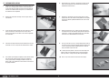
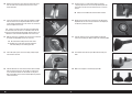
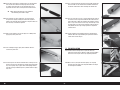
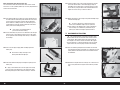
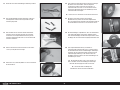
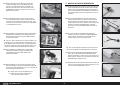
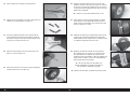
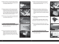
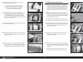
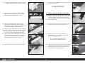
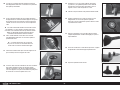
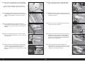
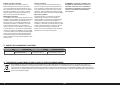
AILERON INSTALLATION
1. Separate the aileron slightly from the wing so the hinges are
visible. Use a felt-tipped pen to make a mark indicating the
center of the hinges on both the aileron and wing. Make the
mark on the underside of the wing so it is less visible when
the model has been completed.
2. Remove the aileron from the wing. Set the hinges aside in a
safe location.
3. Test fi t the white aileron control horn in the slot in the aileron.
Check that the horn is 90-degrees to the surface of the
aileron. If not, lightly trim the hole in the aileron to reposition
the control horn.
4. Place low-tack tape around the aileron control horn. The tape
should be 1/32-inch (1mm) from the control horn as shown.
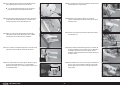
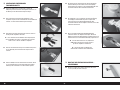
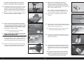
5. Use medium-grit sandpaper to lightly sand the aileron control
horn where it fi ts into the aileron. Clean the sanded area
using a paper towel and isopropyl alcohol to remove any
debris or oils. This provides the surface texture necessary for
the epoxy to bond to.
6. Apply epoxy to the area of the control horns that fi ts into the
slots. Use enough epoxy so the control horns will be fully
bonded to the fi xed surfaces.
7. Remove the control horns from the control surfaces. Apply
epoxy to the slot in the aileron and fl ap. Make sure the epoxy
gets into the slot for a good bond between the surfaces and
control horn.
8. Before the epoxy fully cures, remove the tape from around
the control horn. This will allow the epoxy to fl ow around the
control horn, creating a small fi llet between the control horn
and surface for a fi nished look and secure bond.
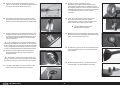
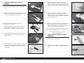
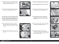
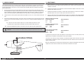
9. Use a pin vise and 1/16-inch (1.5mm) drill bit to drill a hole in
the center of each hinge slot marked previously. Drill the hole
1/4-inch (6mm) deep into the wood. Drill holes in both the
wing and aileron hinges slots now.
Drilling this hole provides a tunnel for the CA to fully wick
into the hinge and surrounding surface. Failure to drill this
hole may result in a hinge that may not be glued properly.
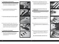
10. Place a T-pin in the center of each of the three hinges.

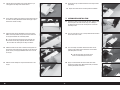
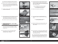
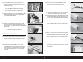
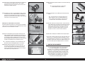
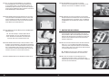
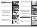
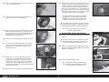
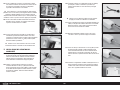
12EN
11. Slide the hinges into position in the aileron with the T-pin
resting against the edge of the control surface.
16. Check both the up and down movement of the hinges before
proceeding.
Repeat this section for the remaining aileron installation.
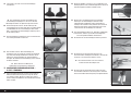
12. Fit the aileron and fl ap to the wing by inserting the hinges into
the slots in the wing. Position the aileron so the gap is equal
between the aileron and wing.
AILERON SERVO INSTALLATION
17. Remove the aileron servo cover from the wing. Tape the string
to the wing so it won’t fall into the wing. Use a toothpick
or hobby knife to puncture the covering for the servo cover
mounting screws.
13. Apply thin CA to the top and bottom of each of the hinges.
Make sure to fully soak the hinges so the CA can wick into
the hinge and bond to the surrounding wood.
Use thin CA so it wicks into the hinge. A thicker CA
will not wick into the hinge properly. Do not to allow the
CA to run over the covering on the wing and aileron.
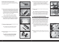
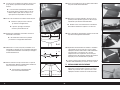
18. Use a pin vise and 3/32-inch (2.5mm) drill bit to drill the holes
for the servo cover screws.
14. Allow the CA to cure for 10 to 15 minutes. Gently pull on the
fi xed surface and control surface to make sure the hinges are
glued securely. If not, apply additional CA to secure each of
the hinges.
19. Use a #2 Phillips screwdriver to thread the M3 x 10 self-
tapping screws into the holes. Remove the screws before
proceeding to the next step.
Do not press down excessively on the
screw as it could damage the structure.
15. Move the aileron through its range of travel to break in the
hinges.
20. Apply a small amount of thin CA to harden the threads
made in the previous step. Allow the CA to fully cure before
installing the aileron servo cover.

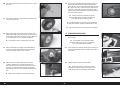
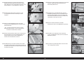
13 EN
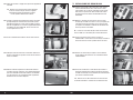
F6F-5 Hellcat 15cc
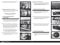
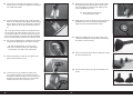
5/8 inch
(16mm)
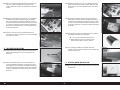
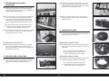
21. Use a pin vise and 5/32-inch (2mm) drill bit to drill the holes
for the servo mounting screws. Make sure to harden the
holes using the technique outlined in the previous steps.
Use the screws provided with the servo and a #1 Phillips
screwdriver when installing the screws.
26. When attaching the linkage to the aileron servo arm, use the
hole in the arm that is 5/8-inch (16mm) from the center of
the arm.
The suggested measurements will result in a scale roll
rate. A longer servo arm can be used for a faster roll rate.
23. Secure the servo to the cover using a #1 Phillips screwdriver
and the screws provided with the servo.
28. Use the string to pull the servo lead through the wing and out
at the root.
22. Install the grommets and eyelets in the servos. Follow any
instructions included with the servo. Prepare both aileron
servos.
27. Tie or tape the string located inside the wing to the end of the
servo lead.
24. Secure a 12-inch (300mm) servo extension to the servo using
a commercially available retainer (SPMA3054).
25. Center the servo, then secure the servo arm so it is
perpendicular to the servo centerline. Use side cutters to
remove any unneeded servo arms.
29. Secure the servo to the wing using four M3 x 10 self-tapping
screws. Use a #2 Phillips screwdriver to tighten the screws.
30. Assemble and attach the aileron linkage to the servo arm. The
aileron pushrod is 2
3
/
8
-inches (60mm) in length.

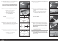
14EN
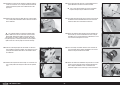
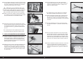
31. Loosen the nuts, then place a drop of threadlock on the
linkage near the clevises. Tighten the nuts over the threadlock
and against the clevises.
Repeat this section for the remaining
aileron servo installation.
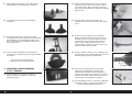
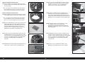
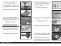
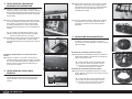
FIXED GEAR INSTALLATION - WIRE STRUT
32. Use a hobby knife with a #11 blade to remove the covering,
exposing the mounts for the fi xed landing gear.
The wire strut can be painted using Royal Blue paint
(TAM81503) so they blend in with the gear doors.
33. Use a drill and 13/64-inch (5mm) drill bit to enlarge the hole
in the wheel for the axle.
34. Use a fl at fi le to create a fl at area on the fi rst 1/4-inch (6mm)
of the landing gear. File a second fl at area that is 1/4-inch
(6mm) wide centered 1
3
/
16
-inches (30mm) from the end of
the axle.
35. Prepare the M3 x 20 socket head cap screws by placing a
washer and lock washer on each screw.
36. Secure the landing gear using the screws prepared in the last
step. Make sure to place a drop of threadlock on each screw
before placing them in position. Use a 2.5mm hex wrench to
tighten the screws.
37. Slide a wheel collar on the axle. Secure the wheel collar
by tightening the M3 x 4 setscrew on the fl at area made
previously. Make sure to place a drop of threadlock on the
setscrew before tightening it using a 1.5mm hex wrench.
38. Apply a drop of light machine oil to the axle.
39. Slide the wheel on the axle. Secure the wheel using a wheel
collar and M3 x 4 setscrew. Apply a drop of threadlock on the
setscrew before tightening it into position using a 1.5mm hex
wrench.
Check that the wheel can rotate freely on the axle.
40. Trim the covering 1/8-inch (3mm) forward and aft of the
notch in the landing gear door to expose the underlying wood.

15 EN
F6F-5 Hellcat 15cc
41. Use medium CA to glue the gear door mounts to the gear
door.
42. Make sure to prepare a left and right gear door.
43. Roughen the wire strut where the gear door mounts meet
the strut. Use 15-minute epoxy and micro balloons to glue
the four gear door brackets to the top and bottom of the gear
door mounts and to the wire strut.
44. Before the epoxy cures, position the landing gear door so it
will not contact the ground during take-off and landing.
Repeat this section for the remaining fixed gear installation.
FIXED GEAR INSTALLATION - E-FLITE
®
SHOCK
ABSORBING STRUT
45. Use a hobby knife with a #11 blade to remove the covering
exposing the mounts for the fi xed landing gear.
46. Use a rotary tool and cut-off wheel to cut the length of
the fi xed gear wire to 13/16-inches (20mm) Use a fl at fi le
to make a fl at area along the front edge of the remaining
landing gear wire.
47. Slide the strut on the landing gear wire. Tighten the
setscrews, securing the strut to the wire.
48. Place the axle in the strut. With the assembly fl at on the work
surface, the body of the mount and axle will lay fl at on the
work surface. If not, fi le the fl at area slightly to change the
positioning of the strut. Once set, the setscrews can have a
drop of threadlock applied and tightened into position using a
2mm hex wrench.
49. Use a pin vise and 1/8-inch (3mm) drill bit to drill the
mounting holes in the landing gear door using the
measurements shown in the photo.
50. Use an M3 x 5 button head screw to temporarily attach the
gear door mounts to the gear doors using the pre-drilled
holes in the gear door. Leave the screws slightly loose so the
mounts can be aligned with the strut. Use a 2mm hex wrench
when installing the screws.
The gear doors can be painted using Royal
Blue paint (TAM81503) so they blend in with
the scale appearance of the model.

16EN
51. Slide the strut through the gear door mounts.
52. Prepare the M3 x 20 socket head cap screws by placing a
washer and lock washer on each screw.
53. Secure the landing gear using the screws prepared in the last
step. Make sure to place a drop of threadlock on each screw
before placing them in position. Use a 2.5mm hex wrench to
tighten the screws.
55. Use a drill and 13/64-inch (5mm) drill bit to enlarge the hole
in the wheel for the axle.
56. Apply a drop of light machine oil to the axle. Slide the axle
into the wheel. Slide a wheel collar on the axle, then secure it
using an M3 x 4 setscrew and 1.5mm hex wrench. Make sure
to use threadlock on the setscrew before installation.
Check that the wheel can rotate freely on the axle.
57. Slide the axle into the strut. Apply a drop of threadlock on
the M3 x 3 setscrew supplied with the struts. Tighten the
setscrew on the fl at using a 1.5mm hex wrench.
58. Position the landing gear door so it will not contact the ground
during take-off and landing. Also check that the gear door
is aligned with the wheel when viewing the door from the
bottom of the wing.
59. Apply a drop of threadlock on the M3 x 4 setscrew. Use a
1.5mm hex wrench to tighten the setscrew in the gear door
mounts. Install all four setscrews, securing the gear door
mounts to the strut. Tighten the button head screws that
secure the gear door to the mounts.
Do not over-tighten the setscrews as this will damage
the gear door mounts or restrict the movement of the strut.
Repeat this section for the remaining fixed gear installation.
54. Use a fl at fi le to make a fl at area for the fi rst 1/2-inch (12mm)
of the axle.

17 EN
F6F-5 Hellcat 15cc
RETRACT WHEEL WELL INSTALLATION
60. Use a hobby knife and #11 blade to remove the covering from
the bottom of the wing to expose the opening for the retract.
61. Test fi t the retract wheel well to the wing. Start trimming the
wheel well at the front to clear the landing gear mounts.
62. Remove the material from the wheel well so it fi ts fl ush with
the wing.
Use care when trimming the plastic pieces to avoid chipping
the paint. The matching paint is listed in the front of this manual.
63. Check the fi t of the retract to the wheel well. It will be
necessary to trim the wheel well accordingly.
64. Use hobby scissors to trim the wheel well to fi t the retract.
Use medium grit sandpaper to smooth any rough edges after
trimming.
65. Lightly sand the outside of the wheel well where it contacts
the wing with medium grit sandpaper. Use a paper towel and
isopropyl alcohol to remove any oil or debris from the wheel
well.
66. Lightly sand the wing 1/8-inch (3mm) from the edge of the
opening with medium grit sandpaper. Use a paper towel and
isopropyl alcohol to remove any oil or debris from the wing
where the wheel well.
67. Use 15-minute epoxy or contact adhesive to glue the wheel
well to the wing. Use low-tack tape to hold the wheel well
tightly in position until the adhesive fully cures.
The wheel wells can be touched up using Royal
Blue paint (TAM81503) so they blend in with the wing.
Repeat this section for the remaining wheel well installation.
RETRACT INSTALLATION - WIRE STRUT
68. Use a fl at fi le to make a fl at area for the fi rst 1/2-inch (12mm)
of the axle.
69. Position the axle on the wire strut so it is 5
1
/
2
-inches (140mm)
from the collar on the strut. This is an approximate position
for the axle.

18EN
70. Guide the lead from the retract along the side of the wheel
well. The lead can be retrieved in the same area as the
aileron extension.
71. Secure the retract in the wing using the hardware included
with the retract. Place a drop of threadlock on each of the
screws before installing them in the retract. Use a 2mm hex
wrench to tighten the screws.
It may be necessary to use the spacers included with
the retracts to make sure there is no torsional stress on the
retract frame when tightened into position. Torsional stress can
sometimes cause intermittent operation of the retract unit.
72. With the gear in the up position, the axle must be centered in
the wheel well. Reposition the axle as necessary.
We recommend making two flat areas with a
file to tighten the screws onto. This will prevent the
axle from rotating on the landing gear wire.
73. Place two nylon spacers on the axle. Apply a drop of light
machine oil on the axle.
74. Slide the wheel on the axle. Place the wheel collar included
with the retracts on the axle. Use the M3 x 3 setscrew to
secure the wheel collar on the axle. Make sure to place a
drop of threadlock on the setscrew before tightening it with a
1.5mm hex wrench.
75. Check that there is a slight amount of toe-in (roughly
1-degree). Adjustments can be made by loosening the two
setscrews on the strut near the mount using a 1.5mm hex
wrench.
Always use threadlock on metal-to-metal fasteners.
76. Double-check that the wheel is centered in the wheel well.
Reposition the axle if necessary or bend the strut slightly so
the wheel is perfectly centered.
77. Trim the covering 1/8-inch (3mm) forward and aft of the
notch in the landing gear door to expose the underlying wood.
78. Use medium CA to glue the gear door mounts to the gear
door.
79. Make sure to prepare a left and right gear door.

19 EN
F6F-5 Hellcat 15cc
Read through the following steps before installing the
gear doors. They must be aligned before the epoxy fully cures.
80. Roughen the wire strut where the gear door mounts meet
the strut. Use 15-minute epoxy and micro balloons to glue
the four gear door brackets to the top and bottom of the gear
door mounts and to the wire strut.
81. Position the landing gear door so it will not contact the ground
during take-off and landing.
82. Retract the landing gear. Position the gear door so it is parallel
to the bottom of the wing. Use a small amount of silicone
adhesive to glue the gear door mounts to the gear wire.
Check the position of the gear door as the adhesive cures.
Repeat this section for the remaining retract installation.
RETRACT INSTALLATION - E-FLITE
®
SHOCK
ABSORBING STRUT
83. Use a rotary tool and cut-off wheel to cut the length of the
retract gear wire to 13/16-inches (20mm) Use a fl at fi le
to make a fl at area along the front edge of the remaining
landing gear wire.
85. Use an M3 x 5 button head screw to temporarily attach the
gear door mounts to the gear doors using the pre-drilled
holes in the gear door. Leave the screws slightly loose so the
mounts can be aligned with the strut. Use a 2mm hex wrench
when installing the screws.
The gear doors can be painted using Royal
Blue paint (TAM81503) so they blend in with
the scale appearance of the model.
86. Slide the strut through the gear door mounts.
87. Fit the strut on the gear wire. Temporarily tighten the
setscrews to secure the strut to the wire using a 2mm hex
wrench.
Do not over-tighten the setscrews
as this may damage the strut.
88. Guide the lead from the retract along the side of the wheel
well. The lead can be retrieved in the same area as the
aileron extension.
89. Secure the retract in the wing using the hardware included
with the retract. Place a drop of threadlock on each of the
screws before installing them in the retract. Use a 2mm hex
wrench to tighten the screws.
It may be necessary to use the spacers included with
the retracts to make sure there is no torsional stress on the
retract frame when tightened into position. Torsional stress can
sometimes cause intermittent operation of the retract unit.
84. Use a pin vise and 1/8-inch (3mm) drill bit to drill the
mounting holes in the landing gear door using the
measurements shown in the photo.

20EN
90. Use a fl at fi le to make a fl at are for the fi rst 1/2-inch (12mm)
of the axle.
91. Use a drill and 13/64-inch (5mm) drill bit to enlarge the hole
in the wheel for the axle.
92. Apply a drop of light machine oil to the axle. Slide the axle
into the wheel. Slide a wheel collar on the axle, then secure it
using an M3 x 4 setscrew and 1.5mm hex wrench. Make sure
to use threadlock on the setscrew before installation.
Check that the wheel can rotate freely on the axle.
93. Slide the axle into the strut. Apply a drop of threadlock on
the M3 x 3 setscrew supplied with the struts. Tighten the
setscrew on the fl at using a 1.5mm hex wrench.
95. Check that the gear good closes fl at against the wing, and
that the door does not interfere with the operation of the
retract. Once set, secure the gear door to the strut using four
M3 x 4 setscrews and a 1.5mm hex wrench. Remember to
tighten the screws holding the door to the mounts using a
2mm hex wrench at this time. Place a drop of threadlock on
all metal-to-metal fasteners.
It may be necessary to lightly file the surface
of the gear door mounts that contact the gear door
so the door will lay flay against the wing.
Do not over-tighten the setscrews as this will damage
the gear door mounts or restrict the movement of the strut.
Repeat this section for the remaining retract installation.
STABILIZER INSTALLATION
96. Remove the two thumb screws that secure the canopy hatch
to the fuselage.
The nylon bolt can be shortened to make
securing the canopy hatch easier. A metal fastener
can also be substituted (not included).
97. Lift the canopy hatch from the fuselage at the rear. Slide the
hatch back and remove it from the fuselage. Set it aside in a
safe location.
94. Check that there is a slight amount of toe-in (roughly
1-degree). Adjustments can be made by loosening the
two setscrews on the strut near the mount using a 1.5mm
hex wrench. The fl at on the retract wire may need slight
adjustment to ensure the retract strut does not rotate on the
wire.
Always use threadlock on metal-to-metal fasteners.
98. Slide the wing tube into the wing tube socket.
The wing tube may be a tight fit in the socket.
Polishing the wing tube with fine sand paper or steel
wool will help ease the installation of the wing tube.
La pagina si sta caricando...
La pagina si sta caricando...
La pagina si sta caricando...
La pagina si sta caricando...
La pagina si sta caricando...
La pagina si sta caricando...
La pagina si sta caricando...
La pagina si sta caricando...
La pagina si sta caricando...
La pagina si sta caricando...
La pagina si sta caricando...
La pagina si sta caricando...
La pagina si sta caricando...
La pagina si sta caricando...
La pagina si sta caricando...
La pagina si sta caricando...
La pagina si sta caricando...
La pagina si sta caricando...
La pagina si sta caricando...
La pagina si sta caricando...
La pagina si sta caricando...
La pagina si sta caricando...
La pagina si sta caricando...
La pagina si sta caricando...
La pagina si sta caricando...
La pagina si sta caricando...
La pagina si sta caricando...
La pagina si sta caricando...
La pagina si sta caricando...
La pagina si sta caricando...
La pagina si sta caricando...
La pagina si sta caricando...
La pagina si sta caricando...
La pagina si sta caricando...
La pagina si sta caricando...
La pagina si sta caricando...
La pagina si sta caricando...
La pagina si sta caricando...
La pagina si sta caricando...
La pagina si sta caricando...
La pagina si sta caricando...
La pagina si sta caricando...
La pagina si sta caricando...
La pagina si sta caricando...
La pagina si sta caricando...
La pagina si sta caricando...
La pagina si sta caricando...
La pagina si sta caricando...
La pagina si sta caricando...
La pagina si sta caricando...
La pagina si sta caricando...
La pagina si sta caricando...
La pagina si sta caricando...
La pagina si sta caricando...
La pagina si sta caricando...
La pagina si sta caricando...
La pagina si sta caricando...
La pagina si sta caricando...
La pagina si sta caricando...
La pagina si sta caricando...
La pagina si sta caricando...
La pagina si sta caricando...
La pagina si sta caricando...
La pagina si sta caricando...
La pagina si sta caricando...
La pagina si sta caricando...
La pagina si sta caricando...
La pagina si sta caricando...
La pagina si sta caricando...
La pagina si sta caricando...
La pagina si sta caricando...
La pagina si sta caricando...
La pagina si sta caricando...
La pagina si sta caricando...
La pagina si sta caricando...
La pagina si sta caricando...
La pagina si sta caricando...
La pagina si sta caricando...
La pagina si sta caricando...
La pagina si sta caricando...
La pagina si sta caricando...
La pagina si sta caricando...
La pagina si sta caricando...
La pagina si sta caricando...
La pagina si sta caricando...
La pagina si sta caricando...
La pagina si sta caricando...
La pagina si sta caricando...
La pagina si sta caricando...
La pagina si sta caricando...
La pagina si sta caricando...
La pagina si sta caricando...
-
 1
1
-
 2
2
-
 3
3
-
 4
4
-
 5
5
-
 6
6
-
 7
7
-
 8
8
-
 9
9
-
 10
10
-
 11
11
-
 12
12
-
 13
13
-
 14
14
-
 15
15
-
 16
16
-
 17
17
-
 18
18
-
 19
19
-
 20
20
-
 21
21
-
 22
22
-
 23
23
-
 24
24
-
 25
25
-
 26
26
-
 27
27
-
 28
28
-
 29
29
-
 30
30
-
 31
31
-
 32
32
-
 33
33
-
 34
34
-
 35
35
-
 36
36
-
 37
37
-
 38
38
-
 39
39
-
 40
40
-
 41
41
-
 42
42
-
 43
43
-
 44
44
-
 45
45
-
 46
46
-
 47
47
-
 48
48
-
 49
49
-
 50
50
-
 51
51
-
 52
52
-
 53
53
-
 54
54
-
 55
55
-
 56
56
-
 57
57
-
 58
58
-
 59
59
-
 60
60
-
 61
61
-
 62
62
-
 63
63
-
 64
64
-
 65
65
-
 66
66
-
 67
67
-
 68
68
-
 69
69
-
 70
70
-
 71
71
-
 72
72
-
 73
73
-
 74
74
-
 75
75
-
 76
76
-
 77
77
-
 78
78
-
 79
79
-
 80
80
-
 81
81
-
 82
82
-
 83
83
-
 84
84
-
 85
85
-
 86
86
-
 87
87
-
 88
88
-
 89
89
-
 90
90
-
 91
91
-
 92
92
-
 93
93
-
 94
94
-
 95
95
-
 96
96
-
 97
97
-
 98
98
-
 99
99
-
 100
100
-
 101
101
-
 102
102
-
 103
103
-
 104
104
-
 105
105
-
 106
106
-
 107
107
-
 108
108
-
 109
109
-
 110
110
-
 111
111
-
 112
112


Hangar 9 HAN2765 Manuale del proprietario
- Categoria
- Giocattoli telecomandati
- Tipo
- Manuale del proprietario
in altre lingue
- English: Hangar 9 HAN2765 Owner's manual
- français: Hangar 9 HAN2765 Le manuel du propriétaire
- Deutsch: Hangar 9 HAN2765 Bedienungsanleitung
Documenti correlati
-
 Hangar 9 HAN2990 Manuale del proprietario
-
 Hangar 9 HAN4670 Manuale del proprietario
-
 Hangar 9 HAN2820 Manuale del proprietario
-
 Hangar 9 HAN4720CR Manuale del proprietario
-
 Hangar 9 P-47D-1 Thunderbolt 60 Manuale utente
-
 Hangar 9 HAN5065 Manuale del proprietario
-
 Hangar 9 HAN4770 Manuale del proprietario
-
 Hangar 9 HAN5080 Manuale del proprietario
-
 Hangar 9 Sbach 342 60 Manuale utente
-
 Hangar 9 HAN2345 Manuale del proprietario


Altri documenti
-
E-flite EFLG715 Istruzioni per l'uso
-
-
E-flite EFL1045016 Manuale utente
-
-
-
E-flite EFLA550 Manuale del proprietario
-
-
-
Blade BLH4925SC Manuale del proprietario
-
E-flite Beast 60e Manuale utente