Kress MBH 2002 Manuale del proprietario
- Categoria
- Martelli perforatori
- Tipo
- Manuale del proprietario

Kress • Titelseite MBH 2002 • OSW 08.01
Bedienungsanleitung 4
Operating Instructions 7
Mode d’emploi 10
Gebruiksaanwijzing 14
Manuale di servizio 17
Instrucciones de servicio 21
Bruksanvisning 24
Betjeningsvejledning 27
Bruksanvisning 30
Käyttöohje 33
Oδηγίες ρήσης
36
D
GB
F
NL
I
E
S
DK
N
FIN
GR
MBH 2002
33415/0
5
07 HD
MBH 2002 - Titel.book Seite 1 Freitag, 10. August 2001 7:52 07

Kress • Bildseite (1) MBH 2002 • OSW 08/01
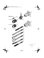
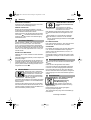
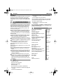
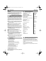
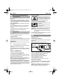
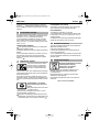
SDS-plus
SDS-plus
1/2" x 20 UNF
Ø 5 - 20 mm
max. Ø 13 mm
max. Ø 13 mm
1/4"/6,3 mm
(DIN 3126, Form C)
13
MBH 2002 - Titel.book Seite 2 Freitag, 10. August 2001 7:52 07

Kress • Bildseite (2) MBH 2002 • OSW 08/01
MBH 2002 - Titel.book Seite 3 Freitag, 10. August 2001 7:52 07
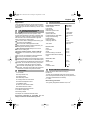
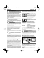
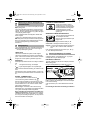
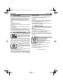
1
2
3
4
5
6
8
9
10
11
12
7

4
Deutsch MBH 2002
Verwendung
Der Pneumatik-Bohrhammer ist universell einsetzbar
zum Hammerbohren, für leichte Meißelarbeiten in
Gestein und zum Bohren sowie Schrauben in Holz,
Metall und Kunststoff.
Bevor Sie die Maschine in Betrieb nehmen, lesen Sie
die Bedienungsanleitung vollständig durch, befolgen
Sie die Sicherheitshinweise in dieser Anleitung sowie
die Allgemeinen Sicherheitshinweise für Elektrowerk-
zeuge im beigelegten Heft.
Wird das Netzkabel während der Arbeit beschä-
digt, sofort Netzstecker ziehen.
Niemals mit beschädigtem Netzkabel arbeiten.
Schutzbrille, Gehörschutz, Schutzhandschuhe und
festes Schuhwerk tragen.
Tragen Sie Gehörschutz. Die Einwirkung von Lärm
kann Gehörverlust bewirken.
Kein asbesthaltiges Material bearbeiten.
Gerät nicht am Kabel tragen.
Steckdosen im Außenbereich müssen über Fehler-
stromschutzschalter (FI-) abgesichert sein.
Um die Maschine zu kennzeichnen, darf das
Gehäuse nicht angebohrt werden. Die Schutzisola-
tion wird überbrückt. Verwenden Sie Klebeschilder.
Wenn der Bohrer unerwartet festklemmt, reagiert
die Maschine ruckartig. Nehmen Sie deshalb
immer einen sicheren Stand ein und halten Sie die
Maschine fest mit beiden Händen.
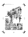
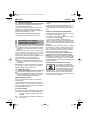
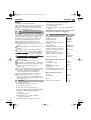
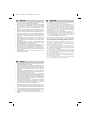
1
Werkzeugaufnahme
2
Staubschutzkappe
3
Entriegelungshülse
4
Drehstoppschalter
5
Feststellknopf für Ein-/Ausschalter
6
Ein-/Ausschalter/Drehzahlsteuerung
7
Lüftungsschlitze
8
Arretierung Netzkabelmodul
9
Drehrichtungsumschalter
10
Umschalter Bohren/Hammerbohren
11
Aufnahme für Tiefenanschlag
12
Zusatzgriff
13
Adapter für Schraub-Bits/Bohrfutter
Abgebildetes oder beschriebenes Zubehör muss
nicht zum Lieferumfang gehören.
Messwerte ermittelt entsprechend EN 60 745.
Gehörschutz tragen!
2
1
Sicherheitshinweise und
Unfallschutz
2 Bild
3
Technische Daten
Pneumatik-Bohrhammer MBH 2002
Artikelnummer 0428 2620
Aufnahmeleistung 600 Watt
Abgabeleistung 300 Watt
Elektronische
Drehzahlsteuerung
•
Leerlaufdrehzahl 0-1050 1/min
Lastdrehzahl 0-800 1/min
Lastschlagzahl beim
Hammerbohren
max.
4274 1/min
Schlagenergie 2,3 J
Rechts-/Linkslauf
•
Spannhals-ø 43 mm
Euro-Norm
Werkzeugaufnahme SDS-Plus
Bohr-Ø max.
Stahl 13 mm
Leichtmetall 15 mm
Holz 30 mm
Hammerbohren in Beton 22 mm
Empfohlener Bohrbereich
Hammerbohren 4-12 mm
Schrauben-Ø max.
Holz 6 mm
Blech 6,3 mm
Gewicht 2,7 kg
Schutzklasse
II /
4
Geräusch-/Vibrationsinformation
MBH 2002 - Titel.book Seite 4 Freitag, 10. August 2001 7:52 07
Die bewertete Beschleunigung beträgt typischer-
weise 8,5 m/s .
Der A-bewertete Geräuschpegel des Geräts beträgt
typischerweise: Schalldruckpegel 89 dB (A);
Schallleistungspegel 100 dB (A). Messunsicherheit
K= 3 dB
Benutzen Sie die mit dem Gerät gelieferten
kann zu Verletzungen führen.
Zusatzhandgriffe. Der Verlust der Kontrolle

MBH 2002 Deutsch
5
Ziehen Sie vor allen Arbeiten am Gerät den Netz-
stecker.
Schließen Sie das Netzkabelmodul an den Handgriff
an. Der Stecker muss einrasten.
Verwenden Sie das Netzkabelmodul nur für Kress-
Elektrowerkzeuge. Versuchen Sie nicht, andere
Geräte damit zu betreiben.
Verwenden Sie nur Original Kress-Netzkabelmodule
und zwar mindestens schwere Gummischlauchlei-
tung (Code-Bezeichnung H07 RN-F).
Prüfen Sie vor Inbetriebnahme, ob die Netzspan-
nung mit der Angabe auf dem Typenschild des
Gerätes übereinstimmt.
EIN-/AUSSCHALTEN
Den Ein-/Ausschalter
6
drücken bzw. wieder loslas-
sen.
Der Ein-/Ausschalter kann mit dem Feststellknopf
5
arretiert werden. Zum Lösen den Ein-/Ausschalter
6
kurz drücken und loslassen.
DREHSTOPP
Mit dem Drehstoppschalter
4
können Sie zwei Ein-
stellungen wählen.
1
= Bohren/Hammerbohren, Rührarbeiten
2
= Keine Drehbewegung: Leichte Meißelarbei-
ten.
Die Umschaltung lässt sich am besten im Stillstand
vornehmen.
Nach Betätigung des Ein-/Ausschalters
6
bzw. beim
Anlaufen der Maschine schaltet das Getriebe in die
vorgewählte Einstellung.
BOHREN - HAMMERBOHREN
Zum Bohren den Umschalter
10
auf stellen.
Zum Hammerbohren auf stellen.
Die Umschaltung lässt sich am besten im Stillstand
vornehmen. Nach Betätigung des Ein-/Ausschalters
6
bzw. beim Anlaufen der Maschine schaltet das
Getriebe in die vorgewählte Einstellung.
Hinweise:
Linkslauf beim Hammerbohren beschädigt
den Bohrer. Bei Arbeiten mit Diamant-Bohrkronen
und bei Rührarbeiten das Schlagwerk ausschalten.
Verwenden Sie beim Hammerbohren ausschließ-
lich hartmetallbestückte Bohrer mit SDS plus-
Schaft.
Die Verwendung handelsüblicher Steinbohrer
mit zylindrischem Schaft unter Verwendung des
Adapters
13
und eines üblichen Bohrfutters unter Ein-
satz des pneumatischen Hammerwerkes ist nicht
möglich.
DREHZAHLSTEUERUNG
Mit dem Ein-/Ausschalter
6
können Sie die Drehzahl stufenlos
steuern. Bei leichtem Druck auf
den Ein-/Ausschalter
6
beginnt die
Maschine langsam zu drehen; mit
zunehmenden Druck erhöht sich
die Drehzahl.
DREHRICHTUNG UMSCHALTEN
Betätigen Sie den Drehrichtungs-
umschalter
9
nur im Stillstand!
Greifen Sie den Drehrichtungsum-
schalter
9
beidseitig.
Rechtslauf:
Drehrichtungsumschalter
9
auf „
R
“
stellen.
Linkslauf:
Drehrichtungsumschalter
9
auf „
L
“
stellen.
Wichtig!
Drehrichtungsumschalter
9
jeweils bis
zum Anschlag am Gehäuse durchdrü-
cken, d. h. bis er spürbar einrastet.
Steht der Drehrichtungsumschalter
9
zwischen Pos.
„
R
“ und „
L
“, kann die Maschine nicht eingeschaltet
werden.
Die Werkzeugaufnahme
1
spannt Bohr- und Meißel-
werkzeuge ohne Werkzeugschlüssel.
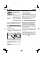
WERKZEUG EINSETZEN
Ziehen Sie vor allen Arbeiten am Gerät den Netz-
stecker.
Reinigen Sie den Werkzeugschaft und fetten Sie ihn
leicht.
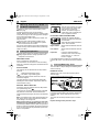
Ziehen Sie die Entriegelungshülse
3
zurück. Führen
Sie das Werkzeug
drehend
in die Werkzeugauf-
nahme ein, bis es einrastet. Lassen Sie die Entriege-
lungshülse los. Prüfen Sie das Werkzeug auf festen
Sitz.
Achten Sie darauf, dass die Staubschutzkappe
2
nicht beschädigt wird.
Beschädigte Staubschutzkappe unbedingt erset-
zen!
5
Zusatzgriff und Netzkabelmodul
montieren
6 Inbetriebnahme
7
Werkzeug einsetzen/entnehmen
Fett
3
MBH 2002 - Titel.book Seite 5 Freitag, 10. August 2001 7:52 07
Betreiben Sie das Gerät nur mit dem Zusatzgriff�12
Montieren Sie den Handgriff auf den Spannhals der
Maschine, drehen Sie ihn in Arbeitsposition und span-
nen Sie ihn mit Hilfe der Griffhülse gut fest.

6
Deutsch MBH 2002
WERKZEUG ENTNEHMEN
Schieben Sie die Entriegelungshülse
3
nach hinten
und ziehen Sie das Werkzeug heraus.
MEISSEL EINSTELLEN
Bringen Sie den Drehstoppschalter
4
in eine Zwi-
schenstellung. Der Meißel lässt sich jetzt von Hand in
die erforderliche Arbeitsposition drehen.
Stellen Sie danach den Drehstoppschalter
4
wieder
auf Position . Der Meißel rastet automatisch ein,
sobald er durch den Arbeits- bzw. Meißelvorgang
radial belastet wird.
Für Bohrarbeiten in Metall, Holz und Kunststoff mit
Bohrern mit normalem Schaft, ist ein Bohrfutter
(max.13 mm Spannweite) lieferbar. Das Bohrfutter
wird auf den Adapter (Zubehör) für Schraub-Bits mon-
tiert. Es können alle üblichen Bohrfutter mit Innenge-
winde 1/2"
×
20 UNF (Spannweite max.13 mm) ver-
wendet werden.
BOHRFUTTER MONTIEREN
Ziehen Sie vor allen Arbeiten am Gerät den Netz-
stecker.
Gewinde am Bohrfutter (Zubehör) und am Adapter
13
(Zubehör) reinigen.
Schrauben Sie das Bohrfutter auf den Adapter und
verriegeln Sie den Adapter wie einen Bohrer in der
Werkzeugaufnahme. Um das Bohrfutter festzuziehen
(30 Nm), stellen Sie den Drehstoppschalter
4
vorü-
bergehend auf Position .
Bohren Sie nicht in verdeckt lie-
gende elektrische Leitungen, Gas-
und Wasserrohre. Untersuchen
Sie vorher die zu bearbeitenden
Flächen; zum Beispiel mit einem
Metallortungsgerät.
Verwenden Sie für Metall nur einwandfrei geschärfte
Bohrer, für Stein und Beton nur hartmetallbestückte
Gesteinsbohrer.
Passen Sie die Drehzahl immer dem zu bearbeiten-
den Werkstoff und dem Bohrerdurchmesser an. Für
genaues Arbeiten in Metall und Holz die Maschine in
einen Bohrständer (Zubehör) setzen.
HAMMERBOHREN - MEISSELN
Schutzbrille und Gehörschutz
tragen.
Üben Sie keinen zu starken
Anpressdruck aus. Die Leistung
wird dadurch nicht erhöht.
Beim Meißeln wird die beste Wirkung erzielt, wenn
nur kleinere Materialstücke herausgebrochen wer-
den.
Beim Meißeln nur mit Schutzbrille und Zusatz-
griff
12
arbeiten. Prüfen Sie vor der Inbetrieb-
nahme, ob der Drehstoppschalter
4
in Stellung
eingerastet ist.
IN FLIESEN BOHREN
Eine Fliese langsam anbohren. Erst wenn die Fliese
durchbohrt ist, auf Hammerbohren umstellen.
SCHRAUBEN
Der Adapter
13
(Zubehör) kann Schraub-Bits aufneh-
men. Es können handelsübliche Bits eingesetzt
werden mit dem Sechskantmaß 6,3 mm bzw. 1/4"
(DIN 3126, Form C).
Schraub-Bits werden im Adapter durch einen Feder-
ring gehalten. Deswegen nur Bits mit Kerben einset-
zen.
Ziehen Sie vor allen Arbeiten am Gerät den Netz-
stecker.
Halten Sie die Lüftungsschlitze stets sauber.
Von außen zugängliche Kunststoffteile regelmäßig
mit einem Tuch ohne Reinigungsmittel abwischen.
Nach starker Beanspruchung über einen längeren
Zeitraum sollte das Gerät zur Inspektion und gründli-
chen Reinigung einer Kress-Servicestelle zugeführt
werden.
8 Bohrfutter (Zubehör)
9 Für die Praxis
10 Wartungsmaßnahmen
11 Umweltschutz
MBH 2002 - Titel.book Seite 6 Freitag, 10. August 2001 7:52 07
Änderungen vorbehalten
Gerät, Zubehör und Verpackung
Diese Anleitung ist aus chlorfrei
gefertigtem
Recycling-Papier hergestellt.
Zum sortenreinen Recycling sind Kunststoffteile ge-
kennzeichnet.
nicht in den Hausmüll.
Werfen Sie Elektrowerkzeuge
statt Müllentsorgung
Rohstoffrückgewinnung
sollten einer umweltgerechten Wieder
verwertung
zugeführt werden.

MBH 2002 English
7
Application
The Pneumatic Drill Hammer can be used universally
for impact drilling, for light chiselling work in masonry
and for drilling as well as screwdriving in wood, metal
and plastic.
Before putting the machine into operation, read
through these operating instructions completely and
observe the safety instructions contained therein as
well as those in the enclosed booklet on general
safety instructions for electro-tools.
If the mains cable is damaged while working, pull
the mains plug immediately.
Never work with a damaged mains cable.
Wear protective glasses, hearing protection, pro-
tective gloves and sturdy shoes.
Wear hearing protection. Exposure to noise
can cause hearing loss.
Do not work with materials containing asbestos.
Do not carry the machine by the cable.
The mains receptacles in the working area must be
protected by a residual current circuit breaker (RC).
For the attachment of identification markings on the
machine, do not drill into the housing. The protec-
tive insulation would be shorted. Use stickers.
When the drill unexpectedly jams, the machine
kicks back. Therefore, always take a secure stance
and hold the machine firmly with both hands.
1
Tool holder
2
Dust protection cap
3
Unlocking collar
4
Rotation stop switch
5
Locking button for on/off switch
6
On/Off switch/Speed control
7
Ventilation slots
8
Latch for mains cable module
9
Rotational direction switch
10
Drilling/Impact drilling selector
11
Holder for depth stop
12
Auxiliary handle
13
Adapter for screwdriver bits/drill chuck
Accessories illustrated or described are not
always included as standard delivery items.
Measured values determined according to
EN 60 7
45.
Typically the A-weighted noise levels of the machine
are: sound pressure level 89 dB (A); sound power level
100 dB (A). Measurement uncertainty
K = 3 dB.
Wear hearing protection!
The typically weighted acceleration is 8,5 m/s
2
.
1
Safety Instructions and
Accident Prevention
2 Illustration
3
Technical Data
Pneumatic Drill Hammer MBH 2002
Article number 0428 2620
Input power 600 W
Output power 300 W
Electronic speed control
•
No-load speed 0-1050 RPM
Speed under load 0-800 RPM
Impact frequency under load
during hammer drilling
4274 per min.
max.
Impact energy 2.3 J
Right/Left rotation
•
Clamping collar dia. 43 mm
Euro standard
Tool holder SDS-Plus
Drill dia., max.
Steel 13 mm
Light metal 15 mm
Wood 30 mm
Hammer drilling in conctrete 22 mm
Recommended hammer drilling
range 4-12 mm
Screw dia., max.
Wood 6 mm
Sheet metal 6.3 mm
Weight 2.7 kg
Protection class II /
4 Noise/vibration information
MBH 2002 - Titel.book Seite 7 Freitag, 10. August 2001 7:52 07
Use the auxiliary handles supplied with the
machine. Loss of control can cause personal
injury.

8 English MBH 2002
Before any work on the machine itself, pull the
mains plug!
Connect the mains cable module to the handle. The
plug must latch.
Use the mains cable module provided only for
Kress Electro-Tools. Do not attempt to operate
other machines with the module.
Use only an original Kress mains cable module that is
at least of heavy rubber sheathed cable (Code desig-
nation H07 RN-F).
Check before putting into operation that the mains
voltage agrees with the voltage specified on the
nameplate of the machine.
SWITCHING ON/OFF
Press or release the on/off switch 6.
The on/off switch can be locked on with the locking
button 5. To release, briefly press and release the on/
off switch 6.
STOP ROTATION
Two settings can be selected with the stop-rotation
switch 4.
1 = Drilling/hammer drilling, stirring
2 = No rotation: Light chiseling jobs.
Changing the setting is best carried out when the
machine is stopped.
The gear switches to the preselected setting after
actuating the on/off switch 6, respectively when the
machine starts running.
DRILLING - IMPACT DRILLING
For drilling, place the selector 10 in the position.
For impact drilling, set to .
The switch-over can best be performed at a standstill.
Only after the on/off switch 6 is actuated and the
machine starts does the gear box shift to the selected
mode.
Note: Left rotation when impact drilling damages the
drill. Switch off the impact mechanism for diamond
crown drilling or for mixing work.
When hammer drilling, use exclusively drills with
hard metal inserts and SDS-Plus shafts. The use of
commercially available masonry drills with cylindrical
shafts by means of the adapter 13 and the normal drill
chuck in conjunction with the pneumatic impact mech-
anism is not possible.
SPEED CONTROL
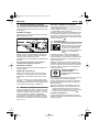
With the on/off switch 6, the speed
can be continuously varied. With
light pressure on the on/off
switch 6, the machine begins to
rotate slowly; with increased pres-
sure, the speed increases.
ROTATIONAL DIRECTION SWITCHING
Operate the rotational direction
switch 9 only when the machine is
at a standstill!
Take hold of the rotational direction
switch 9 on both sides.
Right rotation: Set the rotational direction switch 9
to “R”.
Left rotation: Set the rotational direction switch 9
to “L”.
Important! Press the rotational direction
switch 9 in each case to the stop
on the housing, i. e. until it can
be felt to engage.
If the rotational direction switch 9 is set between the
positions “R” and “L”, the machine cannot be switched
on.
The tool holder 1 clamps drilling and chiselling tools
without a tool key.
INSERTING TOOLS
Before any work on the machine itself, pull the
mains plug!
Clean and lightly grease the tool shaft.
Pull back the unlocking collar 3. Insert the tool while
turning into the tool holder until it latches. Release the
unlocking collar. Check whether the tool is firmly
seated.
Take care that the dust protection cap 2 is not dam-
aged.
Replace damaged dust protection caps!
5
Mounting the Auxiliary Handle and
the Mains Cable Module
6 Putting into Operation
7 Inserting/Removing Tools
Fett
3
MBH 2002 - Titel.book Seite 8 Freitag, 10. August 2001 7:52 07
Operate the machine only with the auxiliary
handle�12. Mount the handle onto the clamping collar
of the drill, turning it to the working position and tight-
ening it using the handle collar.

MBH 2002 English 9
REMOVING TOOLS
Slide the unlocking collar 3 to the rear and pull out the
tool.
ADJUSTING THE CHISEL
Set the rotation stop switch 4 to an intermediate posi-
tion. The chisel can now be turned by hand to the
required working position.
Return the rotation stop switch 4 to the initial position
. The chisel latches automatically as soon as it is
radially loaded by the working or chiselling process.
For drilling work in metal, wood and plastic with drills
that have normal shafts, a drill chuck (13 mm max.
chuck opening) is available. The drill chuck is
mounted on the adapter (accessory) for screwdriver
bits. All common drill chucks with 1/2" x 20 UNF inter-
nal threads (13 mm max. chuck opening) can be
used.
MOUNTING THE CHUCK
Before any work on the machine itself, pull the
mains plug!
Clean the threads of the drill chuck (accessory) and
the adapter 13 (accessory).
Screw the drill chuck onto the adapter and lock the
adapter in the same manner as a drill in the tool
holder. To tighten the drill chuck, set the rotation stop
switch 4 temporarily to position .
Do not drill into hidden electrical
lines or gas and water pipes.
Check the area to be worked with a
metal detector, for example, before
starting.
For metal, use only flawless, sharpened drills; for
stone and concrete, only masonry drills with hard
metal inserts.
Always adapt the speed to the material to be worked
and the diameter of the drill. For precision working
with metal and wood, place the machine in a drill
stand (accessory).
IMPACT DRILLING - CHISELING
Wear protective glasses and
hearing protection.
Do not apply to much pressure.
The performance is not increased
in this manner.
The most effective method for chiselling is to break
out only small pieces of material.
When chiselling, work only with protective glasses
and the auxiliary handle 12. Check before starting
to work if the rotation stop switch 4 is engaged in
the position.
DRILLING IN TILES
Start drilling slowly on the tile. After the tile is drilled
through, switch to impact drilling.
SCREWDRIVING
Screwdriver bits can be inserted into the adapter 13
(accessory). Commercially available bits with a hex-
agonal dimension of 6.3 mm or 1/4" (DIN 3126,
Form C) can be used.
The screwdriver bits are held in the adapter with a
spring ring. Therefore, use only bits with a notch.
Before any work on the machine itself, pull the
mains plug!
Always keep the ventilation slots clean.
Wipe off the accessible plastic parts regularly with a
cloth without cleaning agent.
After heavy use over a long period, the machine
should be taken to a Kress service location for an
inspection and thorough cleaning.
8 Drill Chuck (Accessory)
9 Practical Tips
10 Maintenance Measures
11 Environmental Protection
MBH 2002 - Titel.book Seite 9 Freitag, 10. August 2001 7:52 07
Recycle raw materials instead of dis--
The machine, accessories and packa-
ging should be sorted for environ-
mental friendly recycling.
Subject to change without notice
recycling.
recycled paper
These instructions are printed on
The plastic components are labelled for categorised
manufactured without chlorine.
together with household waste
material!
Do not dispose of electric tools
posing as waste.

10 Français MBH 2002
Utilisation
Ce perforateur pneumatique peut être mis en oeuvre
pour tous les travaux de perforation, de burinage
simple dans la roche ou la pierre, de perçage et de
vissage dans le bois, les métaux et les matières plas-
tiques.
Lire attentivement l’ensemble de la notice d’utilisation
avant de mettre la machine en service. Suivre les con-
signes de sécurité spécifiques figurant dans la pré-
sente notice ainsi que les consignes relatives à la
sécurité en matière d’outillage électro-portatif, défi-
nies dans le feuillet joint.
Si le cordon d’alimentation est endommagé pen-
dant un travail, extraire immédiatement la fiche du
cordon d’alimentation hors de la prise électrique.
Ne jamais travailler avec un cordon d’alimentation
endommagé.
Porter une paire de lunettes de sécurité, une pro-
tection acoustique, une paire de gants de travail
ainsi qu’une paire de solides chaussures.
Portez une protection acoustique. Une forte ex-
position au bruit peut provoquer une perte d'audition.
Ne pas travailler les matériaux contenant de
l’amiante.
Ne jamais porter l’appareil par son cordon d’ali-
mentation.
Les prises électriques situées en extérieur doivent
être protégées par un disjoncteur à courant de
défaut.
Ne jamais percer le carter de cet appareil dans le
but de le marquer ou de l’identifier. Cela court-cir-
cuiterait le dispositif d’isolation électrique. Utiliser
plutôt un autocollant.
Lorsque le foret de la perceuse se coince sans
préavis dans un matériau, la machine réagit bruta-
lement. Il convient donc de toujours adopter une
position de travail sûre et stable et d’utiliser ses
deux mains pour maintenir fermement la machine
en position.
1 Fixation de l’outil
2 Capuchon anti-poussières
3 Bague de verrouillage
4 Stop de frappe
5 Cran d’arrêt de l’interrupteur Arrêt/Marche
6 Interrupteur Arrêt/Marche / Molette de réglage de
la vitesse
7
Ouïes de refroidissement
8 Dispositif de blocage du cordon d’alimentation
modulaire
9 Commutateur du sens de rotation
10 Commutateur perçage simple / avec percussion
11 Dispositif de fixation de la butée de profondeur
12 Poignée supplémentaire
13 Adaptateur pour mandrins et embouts
de tournevis
Les accessoires reproduits et décrits dans la
notice d’instruction ne sont pas forcément com-
pris dans les fournitures.
1
Consignes de sécurité et
prévention des accidents
2 Figure
3 Caractéristiques techniques
Perforateur pneumatique MBH 2002
Référence 0428 2620
Puissance absorbée 600 Watt
Puissance débitée 300 Watt
Régulation électronique du régime
•
Vitesse à vide 0-1050 1/min
Régime en charge 0-800 1/min
Fréquence de frappe en charge lors
de travaux de perçage en frappe
max.
4274 1/min
Travail par coup 2,3 J
Rotation droite et gauche
•
ø du collet de broche 43 mm
(norme eur.)
Fixation de l’outil SDS-Plus
Ø max. des foret
Dans l’acier 13 mm
Dans les alliages légers 15 mm
Dans le bois 30 mm
Travaux de perçage dans le béton
avec le marteau perforateur 22 mm
Diamètre de perçage recommandé
pour le marteau perforateur 4-12 mm
Ø max. des vis
Dans le bois 6 mm
Dans la tôle 6,3 mm
Poids 2,7 kg
Classe de protection II /
MBH 2002 - Titel.book Seite 10 Freitag, 10. August 2001 7:52 07
Utilisez les poignées supplémentaires fournies
avec l'appareil. Le fait de perdre le contrôle
de l'appareil peut entraîner des blessures.

MBH 2002 Français 11
Valeurs de mesure obtenues conformément à la
norme européenne EN 60 745.
Les mesures réelles (A) des niveaux sonores de
l'appareils sont: niveau de pression acoustique
89 dB (A); niveau d'intensité acoustique 100 dB (A).
Incertitude de mesurage K = 3 dB.
Toujours porter une protection acoustique!
L’accélération réelle mesurée est de 8,5 m/s
2
.
Toujours extraire la fiche du cordon d’alimentation
modulaire hors de la prise électrique avant d’entre-
prendre une quelconque intervention sur l’appareil
lui-même.
Raccorder le cordon d’alimentation modulaire à la poi-
gnée de l’appareil. La fiche doit enclencher.
N’utiliser le module de cordon d’alimentation
qu’avec les outillages électroportatifs Kress. Ne
jamais tenter d’y raccorder un appareil d’un autre
constructeur.
N’utiliser que les cordons d’alimentation modulaires
Kress d’origine, à savoir: les gaines en caoutchouc
lourdes (code de référence H07 RN-F).
Avant de mettre l’appareil en service, toujours
s’assurer au préalable que la tension fournie par le
secteur coïncide bien avec celle qui est indiquée
sur la plaquette signalétique de l’appareil.
MISE EN MARCHE / ARRET
Enfoncer, respectivement: relâcher, l’interrupteur
Marche/Arrêt 6.
L’interrupteur Marche/Arrêt peut être verrouillé en
position "Marche" via le cran d’arrêt 5. Pour désacti-
ver ce verrouillage, enfoncer brièvement puis relâcher
l’interrupteur Marche/Arrêt 6.
STOP DE ROTATION
Au moyen du commutateur de stop de rotation 4, il est
possible de choisir entre deux positions différentes.
1 = Perçage / Perçage en frappe, travaux avec
agitateur
2 = Aucun mouvement de rotation : Petits travaux
de burinage.
Le mieux est de commuter à l’arrêt total de la
machine.
Après avoir actionné l’interrupteur Marche / Arrêt 6 ou
lors du démarrage de la machine, l’engrenage
s’enclenche dans la position sélectionnée préalable-
ment.
PERÇAGE - PERÇAGE AVEC PERCUSSION
Pour effectuer un perçage sans percussion, mettre le
commutateur 10 sur la position .
Pour effectuer un perçage avec percussion, mettre le
commutateur sur la position .
Le mieux est de commuter à l’arrêt total de la
machine. Après avoir actionné l’interrupteur Marche /
Arrêt 6 ou lors du démarrage de la machine, l’engre-
nage s’enclenche dans la position sélectionnée préa-
lablement.
Remarque: Lorsqu’un foret est monté sur la broche,
le fait d’utiliser la rotation à gauche endommage le
foret. Lors de travaux avec des couronnes diaman-
tées et lors de travaux avec un agitateur, mettre le
mécanisme de frappe hors fonctionnement.
Pour les travaux de perçage en frappe, utiliser
exclusivement des forets carbure avec queue
SDS-Plus. Il n’est pas possible d’utiliser des forets à
pierre à queue cylindrique, comme on les trouve dans
le commerce, avec l’adaptateur 13 et le mandrin de
perçage habituel en travaillant avec le mécanisme de
frappe pneumatique.
RÉGLAGE DE LA VITESSE DE ROTATION
La conception de l’interrupteur
Marche/Arrêt 6 permet à l’utilisa-
teur de régler la vitesse de rotation
de manière parfaitement continue
et progressive. Une légère pres-
sion sur l’interrupteur Marche/
Arrêt 6 permet de lancer la broche à faible régime.
Plus la pression exercée sur l’interrupteur croît et plus
la vitesse de rotation augmente.
4 Bruits et vibrations
5
Assemblage de la poignée
supplémentaire et du cordon
d’alimentation modulaire
6 Mise en service
MBH 2002 - Titel.book Seite 11 Freitag, 10. August 2001 7:52 07
Cet appareil ne doit être utilisé qu’avec la poignée supplé-
mentaire
�12. Positionner la poignée sur le collier de ser-
rage de la perceuse, la tourner dans la position de travail,
puis bien fixer la poignée en serrant le manche.

12 Français MBH 2002
COMMUTATION DU SENS DE ROTATION
Le commutateur de sens de rota-
tion 9 ne doit être actionné que
lorsque la machine est à l’arrêt
complet!
Saisir le commutateur de sens de
rotation 9.
Rotation à droite: mettre le commutateur de sens
de rotation 9 sur la position „R“.
Rotation à gauche: mettre le commutateur de sens
de rotation 9 sur la position „L“.
Important! Appuyer chaque fois à fond le
commutateur de sens de rota-
tion 9, c’est-à-dire veiller à ce
qu’il s’encliquette de façon per-
ceptible.
Lorsque le commutateur de sens de rotation 9 a été
mis sur une position intermédiaire entre „R“ (rotation
à droite) et „L“ (rotation à gauche), l’appareil ne se
met pas en marche.
La fixation de l’outil 1 est conçue de manière à rece-
voir et à bloquer les forets et autres burins sans l’aide
d’aucune clé.
MISE EN PLACE DE L’OUTIL
Toujours extraire la fiche du cordon d’alimentation
modulaire hors de la prise électrique avant d’entre-
prendre une quelconque intervention sur l’appareil
lui-même.
Nettoyer puis graisser légèrement la queue de l’outil.
Repousser la bague de verrouillage 3 vers l’arrière.
Introduire l’outil dans la fixation tout en imprimant à
l’outil un mouvement de rotation selon son axe princi-
pal, jusqu’à ce qu’il enclenche. Relâcher la bague de
verrouillage 3. Contrôler enfin que l’outil est bien en
place et parfaitement maintenu.
Veiller à ne pas endommager le capuchon anti-pous-
sières 2.
Remplacer sans délai tout capuchon anti-pous-
sières détérioré!
RETRAIT DE L’OUTIL
Repousser la bague de verrouillage 3 vers l’arrière.
Extraire l’outil hors de la fixation.
MISE EN PLACE D’UN BURIN
Mettre le commutateur de stop de frappe 4 dans une
position intermédiaire. Ceci fait, l’outil de burinage se
laisse tourner sans difficulté dans la position de travail
désirée.
Remettre ensuite le commutateur de stop de frappe 4
sur la position . Le burin s’encliquette automati-
quement dès qu’il est sollicité radialement par le pro-
cessus de travail et de burinage.
Pour réaliser des travaux de perçage dans le métal, le
bois et les matières plastiques au moyen d’un foret à
queue cylindrique, l’utilisateur peut faire appel à un
mandrin (de 13 mm d’ouverture maximale), livrable
en tant qu’accessoire. Ce mandrin se monte sur
l’adaptateur (accessoire) permettant d’utiliser le pro-
gramme d’embouts de tournevis. L’appareil est com-
patible avec n’importe quel mandrin conventionnel
doté d’un filetage intérieur 1/2" x 20 UNF (de 13 mm
d’ouverture maximale).
MONTAGE D’UN MANDRIN
Toujours extraire la fiche du cordon d’alimentation
modulaire hors de la prise électrique avant d’entre-
prendre une quelconque intervention sur l’appareil
lui-même.
Nettoyer le filetage du mandrin (accessoire) ainsi que
celui de l’adaptateur 13 (accessoire).
Visser le mandrin sur l’adaptateur. Mettre l’adaptateur
en position dans la fixation d’outil. Le verrouiller
comme s’il s’agissait d’un simple foret. Pour bloquer le
mandrin (30 Nm), mettre le commutateur de stop de
frappe 4 sur la position .
7 Mise en place / Retrait de l’outil
Fett
3
8 Mandrin (accessoire)
MBH 2002 - Titel.book Seite 12 Freitag, 10. August 2001 7:52 07

MBH 2002 Français 13
Ne pas percer de trous à travers
des gaines électriques ou des con-
duites d’eau ou de gaz dissimu-
lées. Avant de percer, procéder
toujours à un examen de la paroi
considérée. Si nécessaire, faire
appel à un détecteur de métal.
Pour percer dans les métaux, il convient de toujours
utiliser un foret parfaitement affûté et en excellent
état. Pour percer la pierre ou le béton, utiliser des
forets à mise au carbure.
Ajuster toujours la vitesse de rotation du foret au
matériau à travailler d’une part et au diamètre du foret
mis en oeuvre d’autre part. Pour travailler de manière
encore plus précise dans les métaux ou dans le bois,
faire appel à un support de preçage (accessoire).
TRAVAUX DE PERFORATION,
DE BURINAGE
Porter des lunettes de sécurité
ainsi qu’une protection acousti-
que.
Ne pas exercer de pression exagérée. Cela ne contri-
bue pas à améliorer les performances de la machine.
Pendant les travaux de burinage, les meilleures per-
formances sont obtenues lorsque les morceaux de
matériau abattus sont de petite taille.
Pendant les travaux de burinage, travailler toujours
avec une paire de lunette de sécurité. La poignée
supplémentaire 12 doit être montée. Avant de
mettre la machine en marche, s’assurer que le
commutateur de stop de frappe 4 est bien dans la
position .
PERÇAGE DANS DU CARRELAGE
Le perçage d’un carreau de faïence doit s’effectuer à
petite vitesse. N’activer le mécanisme de frappe
qu’après avoir complètement traversé le carreau de
faïence.
VISSAGE
L’adaptateur 13 (accessoire) permet d’utiliser les
embouts de tournevis. Il est compatible avec les
embouts de tournevis du commerce dotés d’une
queue six pans de 6,3 mm (1/4", DIN 3126, profil C).
Les embouts de tournevis sont maintenus dans
l’adaptateur par un ressort. Il convient donc de ne tra-
vailler qu’avec des embouts dotés d’une rainure laté-
rale.
Toujours extraire la fiche du cordon d’alimentation
modulaire hors de la prise électrique avant d’entre-
prendre une quelconque intervention sur l’appareil
lui-même.
Les ouïes de refroidissement de la machine doivent
rester propres.
Essuyer régulièrement les pièces en matière plasti-
que accessibles de l’extérieur avec un chiffon humide
mais non imbibé de produit de nettoyage.
Après avoir exploité la machine de manière intensive
pendant une longue période, la confier à un centre de
service agréé Kress afin qu’elle soit inspectée
sérieusement et complètement nettoyée.
9 Conseils pratiques
10 Interventions de maintenance
11
MBH 2002 - Titel.book Seite 13 Freitag, 10. August 2001 7:52 07
Instructions de protection de
l'environnement
Récupération des matières premières
plutôt qu'élimination des déchets
Les appareils, comme d'ailleurs leurs
accessoires et emballages, doivent
pouvoir suivre chacun une voie de
recyclage appropriée.
Ce manuel d'instructions a été fabriqué à partir d'un
papier recyclé blanchi sans chlore.
Nos pièces plastiques ont été marquées en vue d'un
recyclage sélectif des différents matériaux.
Sous réserves de modifications techniques
Ne pas jeter les appareils électriques
dans les ordures ménagères !

14 Nederlands MBH 2002
Gebruik
De pneumatische boorhamer kan universeel worden
toegepast voor hamerboorwerkzaamheden, voor
lichte hakwerkzaamheden in steen en voor het boren
en schroeven in hout, metaal en kunststof.
Voordat u de machine in gebruik neemt, dient u de
gebruiksaanwijzing volledig door te lezen. Neem de
veiligheidsvoorschriften in deze gebruiksaanwijzing
en de algemene veiligheidsvoorschriften voor elektri-
sche gereedschappen in de bijgevoegde brochure in
acht.
Indien de stroomkabel tijdens de werkzaamheden
wordt beschadigd, onmiddellijk de stekker uit het
stopcontact trekken.
Werk nooit met een beschadigde stroomkabel.
Veiligheidsbril, gehoorbescherming, werkhand-
schoenen en stevige schoenen dragen.
Draag een gehoorbescherming. De blootstelling
aan lawaai kan gehoorverlies tot gevolg hebben.
Geen asbesthoudend materiaal bewerken.
Machine niet aan de kabel dragen.
Stopcontacten buitenshuis moeten door middel
van aardlekschakelaars zijn beveiligd.
Voor het aanbrengen van aanduidingen op de
machine mag niet in de behuizing worden geboord.
De veiligheidsisolatie wordt dan overbrugd.
Gebruik stickers.
Wanneer de boor onverwacht vast blijft zitten, rea-
geert de machine met een schok. Zorg er daarom
voor dat u stevig staat en hou de machine met
beide handen stevig vast.
1 Gereedschapopname
2 Stofbeschermingskap
3 Ontgrendelingshuls
4 Draaistopschakelaar
5 Blokkeerknop voor aan/uit-schakelaar
6 Aan/uit-schakelaar en toerentalregeling
7
Ventilatieopeningen
8 Vergrendeling stroomkabelmodule
9 Draairichtingomschakelaar
10 Omschakelaar boren/hamerboren
11 Opname voor diepteaanslag
12 Extra handgreep
13 Adapter voor bits/boorhouder
Niet al het afgebeelde en beschreven toebehoren
wordt meegeleverd.
Meetwaarden vastgesteld volgens EN 60 745.
Het A-gewaardeerde geluidsniveau van de machine
bedraagt kenmerkend: geluidsdrukniveau 89 dB (A);
geluidsvermogenniveau 100 dB (A). Meetonzekerheid
K = 3 dB.
Draag een gehoorbescherming!
De gewaardeerde versnelling bedraagt kenmerkend
8,5 m/s
2
.
1
Veiligheidsvoorschriften en
voorkoming van ongevallen
2 Afbeelding
3 Technische gegevens
Pneumatische boorhamer MBH 2002
Artikelnummer 0428 2620
Opgenomen vermogen 600 watt
Afgegeven vermogen 300 watt
Elektronische toerentalregeling
•
Toerental onbelast 0-1050 o.p.m.
Belast toerental 0-800 o.p.m.
Belast aantal slagen bij hamerboren max.
4274 o.p.m.
Schlagenergie 2,3 J
Rechts- en linksdraaien
•
Spanhals-ø 43 mm
Euro-norm
Gereedschapopname SDS-Plus
Boor-Ø, max.
Staal 13 mm
Licht metaal 15 mm
Hout 30 mm
Hamerboren in beton 22 mm
Geadviseerd boorbereik
bij hamerboren 4-12 mm
Schroef-Ø, max.
Hout 6 mm
Metaalplaat 6,3 mm
Gewicht 2,7 kg
Veiligheidsklasse II /
4 Informatie over geluid en vibratie
MBH 2002 - Titel.book Seite 14 Freitag, 10. August 2001 7:52 07
Gebruik de bij het gereedschap geleverde extra
handgrepen. Het verlies van de controle kan
tot verwondingen leiden.

MBH 2002 Nederlands 15
Trek voordat u werkzaamheden aan de machine
uitvoert altijd de stekker uit het stopcontact.
Sluit de stroomkabelmodule op de handgreep aan. De
stekker moet vastklikken.
Gebruik de stroomkabelmodule alleen voor elek-
trisch gereedschap van Kress. Probeer niet om er
andere machines mee te gebruiken.
Gebruik uitsluitend originele Kress-netkabelmodules
en wel minstens een zware rubberslangleiding (code-
aanduiding H07 RN-F).
Controleer voor de ingebruikneming of de netspan-
ning overeenkomt met de gegevens op het type-
plaatje van de machine.
IN- EN UITSCHAKELEN
De aan/uit-schakelaar 6 indrukken en weer loslaten.
De aan/uit-schakelaar kan met de blokkeerknop 5
worden geblokkeerd. Om de aan/uit-schakelaar 6
weer los te maken, kort indrukken en loslaten.
DRAAISTOP
Met de draaistopschakelaar 4 kunt u twee instellingen
kiezen.
1 = boren/hamerboren, mengwerkzaamheden
2 = geen draaibeweging: lichte hakwerkzaamhe-
den.
De omschakeling kan het best plaatsvinden wanneer
de machine stilstaat.
Na het bedienen van de aan/uit-schakelaar 6 of bij het
aanlopen van de machine schakelt de overbrenging
naar de gekozen instelling.
BOREN EN HAMERBOREN
Om te boren de omschakelaar 10 op instellen.
Om te hamerboren op instellen.
De omschakeling kan het best worden uitgevoerd ter-
wijl de machine stilstaat. Na het bedienen van de aan/
uit-schakelaar 6 of bij het starten van de machine
schakelt de transmissie in de vooraf gekozen instel-
ling.
Aanwijzingen: Linksdraaien bij hamerboren bescha-
digt de boor. Bij werkzaamheden met diamantboor-
kronen en bij mengwerkzaamheden het slagmecha-
nisme uitschakelen.
Gebruik bij het hamerboren uitsluitend hardmeta-
len boren met SDS-Plus-schacht. Het gebruik van
in de handel verkrijgbare steenboren met cilindrische
schacht in combinatie met de adapter 13 en een
gewone boorhouder met toepassing van het pneuma-
tische hamermechanisme is niet mogelijk.
TOERENTALBESTURING
Met de aan/uit-schakelaar 6 kunt u
het toerental traploos besturen. Bij
lichte druk op de aan/uit-schake-
laar 6 begint de machine langzaam
te draaien, bij toenemende druk
wordt het toerental hoger.
DRAAIRICHTING OMSCHAKELEN
Bedien de draairichtingomschake-
laar 9 alleen wanneer de machine
stilstaat.
Pak de draairichtingomschake-
laar 9 aan beide zijden vast.
Rechtsdraaien: Draairichtingomschakelaar 9 op
„R“ instellen.
Linksdraaien: Draairichtingomschakelaar 9 op
„L“ instellen.
Belangrijk! Druk de draairichtingomschake-
laar 9 door tot aan de aanslag op
het huis, dus tot de schakelaar
merkbaar vastklikt.
Indien de draairichtingomschakelaar 9 tussen
pos. „R“ en „L“, staat, kan de machine niet worden
ingeschakeld.
De gereedschapopname 1 span boor- en hakgereed-
schap zonder gereedschapsleutel.
GEREEDSCHAP INZETTEN
Trek voordat u werkzaamheden aan de machine
uitvoert altijd de stekker uit het stopcontact.
Reinig de gereedschapschacht en vet deze licht in.
Trek de ontgrendelingshuls 3 terug. Steek het
gereedschap in de gereedschapopname tot het vast-
klikt. Laat de vergrendelingshuls los. Controleer of het
gereedschap stevig vast zit.
Let er op dat de stofbeschermingskap 2 niet wordt
beschadigd.
Beschadigde stofbeschermingskap beslist ver-
vangen!
5
Extra handgreep en
stroomkabelmodule monteren
6 Ingebruikneming
7
Gereedschap inzetten of
verwijderen
Fett
3
MBH 2002 - Titel.book Seite 15 Freitag, 10. August 2001 7:52 07
Gebruik de machine alleen met de extra hand-
greep�12. Plaats het handvat op de spanhals van de
boormachine. Draai het handvat in de voor de werk-
zaamheden vereiste stand en span het stevig vast
met de huls van het handvat.

16 Nederlands MBH 2002
GEREEDSCHAP VERWIJDEREN
Duw de vergrendelingshuls 3 naar achteren en trek
het gereedschap naar buiten.
BEITEL INSTELLEN
Breng de draaistopschakelaar 4 in een tussenstand.
De beitel kan nu met de hand in de vereiste werkstand
worden gedraaid.
Stel daarna de draaistopschakelaar 4 weer op de
positie in. De beitel klikt automatisch vast zodra
deze bij de werkzaamheden of bij het hakken radiaal
wordt belast.
Voor boorwerkzaamheden in metaal, hout en kunst-
stof met boren met normale schacht is een boorhou-
der (max. 13 mm spanwijdte) leverbaar. De boorhou-
der wordt op de adapter (toebehoren) voor bits
gemonteerd. Alle gebruikelijke boorhouders met bin-
nenschroefdraad 1/2" x 20 UNF (spanwijdte max.
13 mm) kunnen worden gebruikt.
BOORHOUDER MONTEREN
Trek voordat u werkzaamheden aan de machine
uitvoert altijd de stekker uit het stopcontact.
Schroefdraad van boorhouder (toebehoren) en adap-
ter 13 (toebehoren) reinigen.
Schroef de boorhouder op de adapter en vergrendel
de adapter als een boor in de gereedschapopname.
Om de boorhouder vast te draaien (30 Nm), stelt u de
draaistopschakelaar 4 tijdelijk in op positie .
Boor niet in verborgen elektrische
leidingen of in buizen voor gas of
water. Onderzoek eerst het te
bewerken oppervlak, bijvoorbeeld
met een metaaldetector.
Gebruik voor metaal alleen goed geslepen boren,
voor steen en beton alleen hardmetalen steenboren.
Pas het toerental altijd aan het te bewerken materiaal
aan. Voor nauwkeurige werkzaamheden in metaal en
hout de machine in een boorstandaard (toebehoren)
plaatsen.
HAMERBOOR- EN HAKWERK-
ZAAMHEDEN
Draag een veiligheidsbril en een
gehoorbescherming.
Oefen geen te sterke druk uit. Het vermogen wordt
daardoor niet groter.
Bij hakwerkzaamheden wordt het beste resultaat
bereikt wanneer slechts kleine stukken materiaal
worden uitgebroken.
Bij hakwerkzaamheden alleen met veiligheidsbril
en extra handgreep 12 werken. Controleer voor de
ingebruikneming of de draaistopschakelaar 4 in
stand is vastgeklikt.
IN TEGELS BOREN
Een tegel langzaam aanboren. Pas wanneer door de
tegel is geboord, omschakelen naar hamerboren.
SCHROEVEN
De adapter 13 (toebehoren) kan schroefbits opne-
men. Er kunnen normaal in de handel verkrijgbare bits
worden gebruikt met inbusmaat 6,3 mm resp. 1/4"
(DIN 3126, vorm C).
Schroefbits worden in de adapter vastgehouden door
een veerring. Gebruik daarom alleen bits met een
inkeping.
Trek voordat u werkzaamheden aan de machine
uitvoert altijd de stekker uit het stopcontact.
De ventilatieopeningen altijd schoon houden.
Van buiten toegankelijke kunststofonderdelen regel-
matig afvegen met een doek zonder reinigingsmiddel.
Na intensief gebruik gedurende een lange periode
moet de machine voor inspectie en grondige reiniging
naar een Kress-servicewerkplaats worden gebracht
of gestuurd.
8 Boorhouder (toebehoren)
9 Voor de praktijk
10 Onderhoudswerkzaamheden
11 Milieubescherming
MBH 2002 - Titel.book Seite 16 Freitag, 10. August 2001 7:52 07
plaats van het weggooien van afval
Machine, toebehoren en verpakking
moeten op een voor het milieu ver-
antwoorde manier worden hergebruikt.
kunnen recyclen.
Wijzigingen voorbehouden
De kunststof delen zijn gekenmerkt om ze per soort te
gebleekt kringlooppapier.
Terugwinnen van grondstoffen in
Deze gebruiksaanwijzing is vervaardigd van chloorvrij
Geef elektrisch gereedschap niet
met
het huisvuil mee!

MBH 2002 Italiano 17
Applicazione
Il martello perforatore pneumatico può essere utiliz-
zato in maniera universale per forature a martello, per
leggeri lavori di scalpellatura su pietra nonchè per
forare ed avvitare viti nel legno, nel metallo ed in
materiale plastico.
Prima di mettere la macchina in esercizio, leggere
completamente le Istruzioni per l’uso, rispettare le indi-
cazioni di sicurezza contenute nella presente Istru-
zione nonchè le indicazioni generali di sicurezza per
macchine elettriche riportate nell’opuscolo allegato.
Qualora durante l’operazione di lavoro venisse
danneggiato il cavo di rete, estrarre immediata-
mente la spina dalla presa della corrente.
Mai lavorare con un cavo di rete danneggiato.
Portare gli occhiali, la cuffia ed i guanti di prote-
zione, nonchè scarpe di sicurezza.
Indossare una protezione acustica. L'effetto del
rumore può causare la perdita dell'udito.
Non lavorare su materiale contenente amianto.
Non trasportare la macchina tenendola per il
cavo.
Le prese in ambienti esterni devono essere assicu-
rate tramite un interruttore di sicurezza per correnti
di guasto (FI).
Non è permesso perforare la carcassa della mac-
china al fine di volerla contrassegnare. L’isolazione
di protezione viene ponticellata. Utilizzare targhette
autoincollanti.
Se la punta dovesse bloccarsi inaspettativamente,
la macchina reagisce con contraccolpi. Mantenere
perciò sempre una distanza di sicurezza e tenere
bene la macchina con entrambe le mani.
1 Attacco utensili
2 Protezione antipolvere
3 Boccola di sbloccaggio
4 Commutatore rotante
5 Pulsante di bloccaggio per interruttore di
inserimento/disinserimento
6 Interruttore di inserimento/disinserimento /
comando numero di giri
7
Feritoia di ventilazione
8 Blocco del modulo cavo di retel
9 Commutatore per la reversibilità
10 Selettore Foratura / Foratura a martello
11 Attacco per battuta di profondità
12 Impugnatura supplementare
13 Adattatore per bit cacciaviti - mandrino portapunta
Accessori illustrati o descritti non fanno necessa-
riamente parte del volume di consegna.
Valori misurati conformemente alla norma EN 60 745.
La misurazione A del livello di pressione acustica della
macchina è solitamente di pressione acustica 89 dB (A);
livello della potenza sonora 100 dB (A).
Incertezza della misura K = 3 dB.
Usare auricolari di protezione!
L'accelerazione misurata raggiunge di solito il valore
di 8,5 m/s
2
.
1
Indicazioni di sicurezza e
misure antinfortunistiche
2 Figura
3 Dati tecnici
Martello perforatore pneumatico MBH 2002
Codice di ordinazione 0428 2620
Potenza assorbita 600 Watt
Potenza resa 300 Watt
Comando elettronico numero di giri
•
Num. di giri a vuoto 0-1050 1/min
Numero di giri sotto carico 0-800 1/min
Numero battute durante la foratura
a martello
mass.
4274 1/min
Potenza della percussione 2,3 J
Funzionamento reversibile
•
Diametro collare ø 43 mm
Norma Euro
Attacco utensili SDS-Plus
Diametro punta, mass.
Acciaio 13 mm
Metallo leggero 15 mm
Legno 30 mm
Foratura a martello nel calcestruzzo 22 mm
Campo di foratura consigliato
per foratura a martello 4-12 mm
Diametro viti, mass.
Legno 6 mm
Lamiera 6,3 mm
Peso 2,7 kg
Classe di protezione II /
4
Informazioni sulla rumorosità
e sulla vibrazione
MBH 2002 - Titel.book Seite 17 Freitag, 10. August 2001 7:52 07
Utilizzare le impugnature supplementari fornite
in dotazione con la macchina. La perdita di
controllo della macchina può provocare incidenti.

18 Italiano MBH 2002
Prima di ogni intervento alla macchina, estrarre la
spina dalla prese di rete.
Collegare il modulo del cavo di rete all’impugnatura.
La spina deve innestarsi in posizione.
Utilizzare il modulo di cavo di rete esclusivamente
per elettroutensili Kress. Non tentare di utilizzare il
modulo in combinazione con altre macchine.
Impiegare esclusivamente moduli del cavo di rete ori-
ginali Kress e, cioè, almeno pesanti fili isolati in
gomma (codice commerciale H07 RN-F).
Prima della messa in esercizio, controllare che la
tensione di rete corrisponda ai valori indicati sulla
targhetta di costruzione della macchina.
INSERIMENTO-DISINSERIMENTO
Premere oppure lasciare l’interruttore di inserimento/
disinserimento 6.
L’interruttore di inserimento/disinserimento può
essere bloccato con il pulsante di fissaggio 5. Per
sbloccare, premere brevemente l’interruttore di inse-
rimento/disinserimento 6 e lasciarlo.
ROTOSTOP
Tramite il commutatore rotante 4 è possibile selezio-
nare due registrazioni.
1 = foratura/foratura a martello, lavori di miscela-
zione
2 = Senza rotazione: Leggeri lavori di scalpella-
tura.
La commutazione deve essere eseguita preferibil-
mente quando la macchina è ferma.
Una volta attivato l'interruttore avvio/arresto 6 oppure
al momento dell'avvio della macchina, il motore passa
al modo di esercizio precedentemente selezionato.
FORATURA - FORATURA A MARTELLO
Per forare, mettere il selettore 10 in posizione .
Per foratura a martello metterlo in posizione .
Il modo più semplice di eseguire la commutazione è
quando la macchina è ferma. Azionando l’interruttore
di inserimento-disinserimento 6 opp. all’avvio della
macchina, la trasmissione passa all’impostazione
preselezionata.
Indicazioni: La rotazione sinistrorsa nel corso di fora-
tura a martello danneggia la punta. Lavorando con
una corona a forare diamantata ed in caso di lavori di
miscelazione è indispensabile disinserire il sistema
battente.
In caso di foratura a martello è indispensabile uti-
lizzare esclusivamente punte con applicazioni di
placchette di metallo duro e con un gambo SDS-
plus. Non è possibile utilizzare punte per pietra comu-
nemente in commercio con gambo cilindrico ed adat-
tatore 13 né è possibile utilizzare un comune man-
drino portapunta in caso di impiego del martello pneu-
matico.
COMANDO NUMERO DI GIRI
Tramite l’interruttore di inseri-
mento/disinserimento 6 è possibile
regolare il numero di giri a varia-
zione continua. Premendo legger-
mente sull’interruttore di inseri-
mento/disinserimento 6 la mac-
china comincia a girare lentamente; il numero di giri
sale aumentando la pressione esercitata.
INVERSIONE DELLA DIREZIONE DI MARCIA
Azionare il commutatore per la
reversibilità 9 solo a macchina
ferma!
Afferrare il commutatore per la
reversibilità 9 per entrambi i lati.
Rotazione destrorsa: mettere il commutatore per
la reversibilità 9 nella posi-
zione „R“.
Rotazione sinistrorsa: mettere il commutatore per
la reversibilità 9 nella posi-
zione „L“.
Importante! Premere rispettivamente il commutatore
per la reversibilità 9 fino alla battuta nella
carcassa, cioè, fino a percepirne l’inca-
stro.
Se il commutatore per la reversibilità 9 si trova tra la
posizione „R“ e „L“, la macchina non può essere
messa in esercizio.
5
Montaggio dell’impugnatura
supplementare e del modulo del
cavo di rete
6 Messa in esercizio
MBH 2002 - Titel.book Seite 18 Freitag, 10. August 2001 7:52 07
Utilizzare la macchina con l’impugnatura supplemen-
tare�12. Applicare la maniglia sul collare dell’alberino del
trapano, ruotarla in posizione operativa e fissarla salda-
mente avvitando l’impugnatura. Soltanto in questo si evita
che la maniglia sul collare dell’alberino si sposti o si stac-
chi dall’apparecchio.

MBH 2002 Italiano 19
L’attacco utensili 1 blocca gli utensili di foratura e gli
utensili per scalpellare senza dover ricorrere all’ausi-
lio di attrezzi.
INSERIRE L’UTENSILE
Prima di ogni intervento alla macchina, estrarre la
spina dalla prese di rete.
Pulire il gambo dell’utensile e lubrificarlo leggermente.
Estrarre all’indietro la boccola di sbloccaggio 3. Ruo-
tandolo, inserire l’utensile nell’attacco utensili fino a
quando fa presa. Lasciare il mandrino di serraggio.
Controllare che l’utensile sia ben fisso.
Fare attenzione a non danneggiare la protezione anti-
polvere 2.
Se la protezione antipolvere è danneggiata, è
estremamente importante sostituirla!
ESTRARRE L’UTENSILE
Spingere all’indietro la boccola di sbloccaggio 3 ed
estrarre l’utensile.
REGOLARE LO SCALPELLO
Mettere il commutatore rotante 4 in una posizione
intermedia. Lo scalpello può dunque essere girato
manualmente nella posizione di lavoro che si desi-
dera.
In seguito, rimettere il commutatore rotante 4 nella
posizione . Lo scalpello fa presa automaticamente
non appena viene sottoposto a carico radiale tramite
il processo di lavorazione opp. scalpellatura..
Per lavori di foratura nel metallo, nel legno e in mate-
riali artificiali tramite punte con un gambo normale, è
fornibile un mandrino portapunta (mass. 13 mm aper-
tura). Il mandrino viene montato sull’adattatore
(accessorio) per bit cacciaviti. è possibile utilizzare
tutti i mandrini comunemente reperibili sul mercato
che abbiano una madrevite 1/2" × 20 UNF (apertura
mass. 13 mm).
MONTARE IL MANDRINO PORTAPUNTA
Prima di ogni intervento alla macchina, estrarre la
spina dalla prese di rete.
Pulire la filettatura al mandrino portapunta (accesso-
rio) ed all’adattatore 13 (accessorio).
Avvitare il mandrino portapunta sull’adattatore e bloc-
care l’adattatore nell’attacco utensili come se fosse
una punta. Per avvitare bene (30 Nm) il mandrino por-
tapunta, mettere il commutatore rotante 4 provvisoria-
mente sulla posizione .
Non forare linee elettriche, nonchè
tubazioni di gas e di acqua posate
in maniera non visibile. Prima di
cominciare con l’operazione di
foratura, controllare le superfici uti-
lizzando p.e. un rilevatore di
metalli.
Per forare nel metallo, utilizzare esclusivamente
punte perfettamente in ordine e bene affilate; per
forare nella pietra e nel calcestruzzo, utilizzare esclu-
sivamente punte per pietra con applicazioni di plac-
chette di metallo duro.
Regolare il numero di giri sempre in base al tipo di
materiale in lavorazione ed in base al diametro della
punta. Per eseguire lavori di precisione nel metallo e
nel legno, fissare la macchina in un montante per
foratura (accessorio).
FORATURA A MARTELLO -
SCALPELLATURA
Portare occhiali e cuffie di di
protezione.
Non esercitare una pressione troppo forte: non è così
che si raggiunge una prestazione maggiore.
Durante l’operazione di scalpellatura si raggiunge il
miglior effetto scalpellando di volta in volta piccoli
pezzi di materiale.
Durante l’operazione di scalpellatura, lavorare
sempre portando gli occhiali di protezione e con
l’impugnatura supplementare 12. Prima della
messa in esercizio, controllare che il commutatore
rotante 4 si sia innestato nella posizione .
FORARE LE PIASTRELLE
Preforare delicatamente la piastrella ed inserire la
foratura a martello solo dopo aver perforato completa-
mente la piastrella.
7 Inserire ed estrarre gli utensili
8 Mandrino portapunta (Accessorio)
Fett
3
9 Consigli pratici
MBH 2002 - Titel.book Seite 19 Freitag, 10. August 2001 7:52 07

20 Italiano MBH 2002
AVVITARE
L’adattatore 13 (accessorio) può alloggiare bit cac-
ciaviti. Possono essere utilizzati bit cacciaviti comune-
mente reperibili sul mercato e che abbiano un dado
esagonale da 6,3 mm opp. 1/4" (DIN 3126, Forma C).
I bit cacciaviti vengono tenuti nell’adattatore tramite
una rondella. Per questo motivo, utilizzare soltanto bit
che abbiano apposite tacche.
Prima di ogni intervento alla macchina, estrarre la
spina dalla prese di rete.
Mantenere sempre pulite le feritoie di ventilazione.
Pulire regolarmente con uno straccio e senza deter-
genti, parti in materiale artificiale che siano accessibili
dall’esterno.
Dopo un periodo abbastanza lungo in cui la macchina
sia stata soggetta a condizioni operative estreme,
sarà necessario affidare la macchina ad un Centro di
servizio Kress perchè venga eseguita una ispezione
ed una minuziosa pulizia.
10 Disposizioni di manutenzione
11 Misure ecologiche
MBH 2002 - Titel.book Seite 20 Freitag, 10. August 2001 7:52 07
Recupero di materie prime, piuttosto
che smaltimento di rifiuti
Macchina, accessori ed imballaggio
dovrebbero essere inviati ad una
riutilizzazione ecologica.
Queste istruzioni sono stampate su
I componenti in plastica sono contrassegnati
Con riserva di modifiche
Non gettare le apparecchiature
elettriche tra i rifiuti domestici.
per il riciclaggio selezionato.
carta riciclata
sbiancata senza cloro.
La pagina si sta caricando...
La pagina si sta caricando...
La pagina si sta caricando...
La pagina si sta caricando...
La pagina si sta caricando...
La pagina si sta caricando...
La pagina si sta caricando...
La pagina si sta caricando...
La pagina si sta caricando...
La pagina si sta caricando...
La pagina si sta caricando...
La pagina si sta caricando...
La pagina si sta caricando...
La pagina si sta caricando...
La pagina si sta caricando...
La pagina si sta caricando...
La pagina si sta caricando...
La pagina si sta caricando...
La pagina si sta caricando...
La pagina si sta caricando...
La pagina si sta caricando...
La pagina si sta caricando...
La pagina si sta caricando...
La pagina si sta caricando...
-
 1
1
-
 2
2
-
 3
3
-
 4
4
-
 5
5
-
 6
6
-
 7
7
-
 8
8
-
 9
9
-
 10
10
-
 11
11
-
 12
12
-
 13
13
-
 14
14
-
 15
15
-
 16
16
-
 17
17
-
 18
18
-
 19
19
-
 20
20
-
 21
21
-
 22
22
-
 23
23
-
 24
24
-
 25
25
-
 26
26
-
 27
27
-
 28
28
-
 29
29
-
 30
30
-
 31
31
-
 32
32
-
 33
33
-
 34
34
-
 35
35
-
 36
36
-
 37
37
-
 38
38
-
 39
39
-
 40
40
-
 41
41
-
 42
42
-
 43
43
-
 44
44


Kress MBH 2002 Manuale del proprietario
- Categoria
- Martelli perforatori
- Tipo
- Manuale del proprietario
in altre lingue
- English: Kress MBH 2002 Owner's manual
- français: Kress MBH 2002 Le manuel du propriétaire
- español: Kress MBH 2002 El manual del propietario
- Deutsch: Kress MBH 2002 Bedienungsanleitung
- Nederlands: Kress MBH 2002 de handleiding
- dansk: Kress MBH 2002 Brugervejledning
- svenska: Kress MBH 2002 Bruksanvisning
- suomi: Kress MBH 2002 Omistajan opas
Documenti correlati
Altri documenti
-
Flex BRL 3501 A Manuale utente
-
AEG PN 6000 S Manuale del proprietario
-
-
Bosch GBH Professional Istruzioni per l'uso
-
Bosch PBH 3000 FRE Set Manuale del proprietario
-
Bosch GBH 2-26 DRE Istruzioni per l'uso
-
Bosch PBH 2000 SRE Manuale del proprietario
-
-
Milwaukee PFH 20 E Instructions For Use Manual
-
Metabo Angle drill.and screwdriv.attachment Istruzioni per l'uso